Note: Descriptions are shown in the official language in which they were submitted.
1306215
DUPLEX CONVEYER
The invention relates to a duplex conveyer such as
specified in the precharacterizing part of claim 1.
For manufacturing equipment, in particular assembly
lines, use has been made of duplex conveyers
comprising two parallel conveyer belts on which
pallets are placed to convey workpieces between
handling positions of which one or a plurality may be
provided in the course of the duplex conveyer. At said
positions, the pallet is arrested, lifted locally and
stopped while the belt conveyer further moves forward
beneath the pallet. The known conveyer and handling
systems are individually constructed and assembled
in accordance with the respective requirements. To
this effect, modular designs including specific
profiles and corner brackets may be used. A specific
problem is involved with the separation of the pallets
conveyed in close succession on the belt conveyer. If
one of said pallets is dismissed from the handling
station, the following pallets which, before, were
slidingly retained on the moving conveyer belts have
to be advanced by one pallet length. Said stepwise
advance by exactly one pallet length entails
difficulties because it is practically impossible to
selectively engage by means of a ~ p member the gap
between two successive pallets.
The known duplex belt conveyers imply another
difficulty in that auxiliary members such as clamping
means, proximity switches, keys etc. may be mounted
,
.
'~ . : ' ' ., '
~ `
~306~15
only with an extensive assembly work and that it is
difficult to equip the handling stations with
components provided to this ef~ect and including also
the separating means.
Finally, it is another handicap that conveyer lines of
a manufacturing plant have to be tailored individually
to the prevailing needs and that, up to the present,
it has been impossible to simply intercombine handling
unit~ which may be separately prefabricated as
modules, because expensive assembly works were always
necessary for joining them conveniently.
It is an ob~ect of the invention to provide improvements
in duplex conveyors.
According to the invention a conveyor particularly
sdapted for manufacturing in~tallation~ compri8es two
generally parallel longitudinal profiles adapted to
support a conveyor. Each profile includes an upright
stem defining inner and outer sides. A leg pro~ects
generally transversely from the inner side of each
upright stem and carries a vertical clamping bar. The
profiles are disposed with the legs thereof pro~ecting
toward each other and the legs are adapted to support
thereupon a conveyor. A retaining strip pro~ects
generally transversely from the outer side of each
upright stem.
In one aspect of the invention, each retaining strip in
part defines a longitudinal groove and has an exterior
longitudinally extending inclined surface disposed in
inclined relationship to a longitudinal plane of its
associated upright stem. A clamping block is carried by
at lea~t one of the retaining strips, and locking means
i8 carried by the clamping block for bearing against the
,
!
" 1306;~15
inclined surface for selectively securing the clamping
block to the said one retaining strip.
In another aspect of the invention, a clamping bar
pro~ects generally transversely from the inner side of
each upright stem and means is provided for clamping a
transverse rail to the clamping bars. The conveyor also
includes means carried by the transverse rail for
manipulating a conveyor supported upon the transversely
projecting legs.
In a still further aspect of the invention, the conveyor
includes a conveyor belt having a conveyor run in sliding
relationship on each of the transversely projecting legs,
and each vertical clamping bar pro~ects downwardly.
The clamping bar may be integrally formed with the
contact surfaces of the profiles. As a result thereof,
at any optional site of the conveyer line, additional
means such as proximity initiators, switches or the like
may be mounted and simply adjusted beneath the pallet
path, e.g. to operate the pin of the separation means
or to cause the lifting of the pallet from the
conveyer elements. At the retainer strip provided at
the outside of the stem, the clamping block for
lifting and retaining the pallet may be fixed
interchangeably by simple clamping or tensioning means
and it may be adjusted or exactly positioned
accordingly.
; Suitably, the profiles forming the carrying elements
o the duplex conveyer are mounted on a support. A
plurality of such supports of which each comprises at
least a complete conveyer may be composed to form a
manufacturing plant, wherein the conveyers of
-: :
3062~5
different supports are either mutually aligned or
positioned at right angles with respect to each other.
Thus, due to the duplex conveyer of the invention,
different manufacturing or handling systems may be
combined of several mudular units of which each
includes at least one independent conveyer.
An embodiment of the invention will be now explained
in more detail with reference to the arawings in which
Fig. 1 shows a side view of a support with profiles
for the formation of belt conveyers,
Fig. 2 is plan view of the support of Fig. 1 including
five belt conveyers in total,
Fig. 3 is a view of the support of Fig. 1 from the
direction of arrow III,
Fig. 4 is an end view of the handling station in the
form of a section along line IV-IV of Fig. 1,
Fig. 5 is a plan view of a pal~et,
.
Fig. 6 is a bottom view of the pallet of Fig. S,
Fig. 7 is a view of the pallet from the direction of
arrow VII of Fig. 6,
:
Fig. 8 is a section along line VIII-VIII of Fig. 5,
,:
Fig. 9 is a plan view of the handling station of Fig.
, 4,
.. :
..... : :
:
~ 1306215
-- 5 --
Fig. 10 is a plan view of a turning station for
turning a pallet in both senses by 90,
Fig. 11 is a section along line XI-XI of Fig. 10.
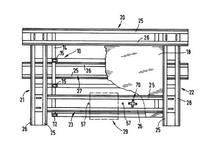
The support 10 shown in Figs. 1 to 3 constitutes the
basic unit of a universal manufacturing assembly
forming part of a manufacturing plant, said support
comprising four upright columns 12 positioned on the
ground by feet ll and being interconnected by a
horizontal lower frame 13 and a horizontal upper frame
14. In the end sides of support 10 between column 12,
there extend two vertical bars 15 subdividing the
interior of the support into three juxtaposed
compartments 16a,16b,16c. The lower frame 13 is
provided with sleeve eléments 17 welded thereto for
gripping or seizing frame 14 by the forks of a fork
lifter, of an industrial trucks or the like. In
longitudinal direction, the rectangular upper frame 14
and the rectangular lower frame I3 protrude
horizontally beyond the columns 12 (Fig. 1).
. ~ .
On the upper frame 14 of support 10, there is fixed a
table plate 18 with T-shaped grooves which serve as a
fixation element for devices and handling means, and
as a working plate, a plate of deposit, and an
assembly plate. On the table plate, there are arranged
four horizontal belt conveyers 21, 22 and 23 forming a
rectangle. The belt conveyer 20 moving lengthwise
for~s a main transport line while the three other belt
I conveyers 22, 23 and 21 form a bypass transport line.
Figs. l to 3 only show the two stationary profiles
i 25,26 of each belt conveyer for guiding the two
conveyer belts, which, as such, as well as the
auxiliary and additional means are not illustrated for
the sake of clarity.
~'' .
,- .-' ~
.
~306215
The two con~reyers 20 and 23 are mounted above the two
outer compartments 16a and 16c, while, in the central
compartment 16b, on the lower frame 13, a return
movement conveyer 27 is fixed. A11 of the belt
conveyers 20,21,22,23 and 27
are o~ an equal design which, based on belt conveyer
23, will be still explained hereunder in more detail
/
The belt conveyers are used to transport the pallets
28 shown in Fiqs. 5 to 8 on which pallets a
corresponding take-up for fixing tools is fastened. In
the course of the belt conveyer 23, there is provided
a processing station 29 at which the pallets conducted
via the bypass transport line, may be arrested
individually in order to carry out treating, mounting
or other operations at the workpieces. ~n advance of
the handling station 29, a turning station 70 permits
to turn the pallets by 90 in a horizontal plane.
The embodiment of profiles 25 and 26 is evident from
Fig. 4 showing that each profile contains an upright
stem 30 whose lower end has an outwardly projecting
flange 31 secured by screws to plate 18 or to another
support. From stem 30, a clamping bar 33 extends
horizontally towards the inside, said bar being
somewhat higher than flange 31 and being underengaged
by the transverse rail 34 extending between both
profiles 25 and 26 at whose clamping bars 33 it is
clamped by shims 35 and screws 36. If the ends of the
rail 34 underengage the clamping bars 33, such as
illustrated in Fig. 4, the shims 35 overengage the
clamping bars 33. It is also possible to cause rail 34
to press from above against the clamping bars 33,
while, if so, the shims 35 press from below against
them.
.
.
'
1306~15
A transverse shaft 37 extends between stems 30 of the
two profiles 25 and 26 to keep said rails in the
desired mutual spaced relationship. The ends of shaft
37 are fixed by screws with profiles 25 and 26.
Near the upper end of each stem 30, a running board 38
projects inwardly from said stem, in other words, the
ends of said running boards 38 are confronted with
each other. The top side of the running board 38 is
provided with a coating forming the slide face 39 for
the upper half 40a or 41a of the conveyer belt 40 or
41. The lower half 40b or 41b extends at a vertical
distance beneath the appertaining running board 38
above shaft 37.
From the inner end of each running board 38, a
clamping bar 42 projects downwardly, said clamping
bars 42 having triangular grooves 43 at their
confronted vertical surfaces. To each clamping bar 42,
additional elements such as switches, proximity
initiators etc. may be secured by clamps 44, at an
optional site of the profile length. Clamps 44 enclose
the clamping bar 42 in a U-shaped manner, and they are
fixed by a screw whose point penetrates into groove
~1 43. The clamps 44 are placed from below on the
clamping bar 42.
In the vicinity of the upper end of stem 30, an
L-shaped retaining strip 45 extends outwardly in
opposite direction to the running board 38. The
~,~ outside of the upwardly extending outer leg of the
retaining strip 45 contains a V-shaped groove 46. Said
leg together with the upper end 47 of stem 30 forms a
vertical groove 48. The external lower edge of the
retaining strip 45 forms an inclined plane 49. At the
inside of end 47 of stem 30, there protrudes the
external leg 39a of the sliding surface 39, said leg
,
,
. :
,, . - , .
. . , ., . : - .
:. , ~
.. . .
~ 1~062~S
39a thus forming a lateral limitation for the upper
belt half 40a or 41a and a lateral boundary for the
pallet 28.
The L-shaped retaining strip 45 serves for the
rixation of a clamping block 50 penetrating with a
downwardly projecting nose 51 into groove 48 and
overengaging the vertical leg of holding bar 45. In
the vicinity of the lower end of the clamping block
50, there is seated a clamping screw 52 in a thread
bore pointing obliquely upwardly. The front end of
said clamping screw 52 rectangularly urges against
the inclined surface 49 thus tightening the clamping
block 50 at the retaining strip 45. The nose 51 of the
clamping block 50 is provided with a leaf spring 53
pressing the clamping screw 52 against the inclined
surface 49 thus excluding the risk that the clamping
~crew 52 is unscrewed unintentionally by vibrations or
the like.
The two profiles 25 and 26 are of a complementary
design. The end of each profile is provided with
~non-illustrated) guide rolls in order to reroute the
appertaining conveyer belt 40 or 41. One of said guide
rolls is driven.
Each clamping block 50 includes a pin 55 adapted to be
moved out towards the side face of the pallet 28 and
whose point may penetrate into a V-groove 54 in the
vertical side edge of pallet 28. As evident from Fig.
4, pins 55 are somewhat higher than the V-grooves 54.
If pins 55 are approached towards each other to
penetrate into the V-grooves 54, they slightly lift
the pallet 28 from the conveyer belts 40 and 41 so
that the conveyer belts travel on while the pallet is
arrested.
.
130621S
To arrest the pallet 28 in the desired position at
handling station 29, a separating means 56 fixed to
rail 44 is provided at said handling station, the
separating means 56 including a plug 57 arranged
betw~en the conveyer belts 40 and 41 beneath the
travel path of the pallets, it being possible to
advance said plug 57 out of a housing 58 into the
transport path so that the front edge of the pallet
abuts against it. As soon as the pallet front edge has
reached said plug 57, the pins 55 are moved out in
order to lift the pallet from the duplex belt conveyer
comprising the two conveyer belts.
As shown in Figs. 5 to 8, the pallet 28 is
square-shaped, its central region having a vertically
continuous opening 60. The underside of the pallet ~s
provided with two guide grooves 62,63 extending in
conveying direction 61 of which guide groove 62,
in the front portion, extends from the front edge to
recess 60 while guide groove 63 extends from recess 60
to the rear edge. Said guide grooves 62 and 63 are not
situated along a common axis, but with respect to the
longitudinal center axis 64, guide groove 62 is offset
in one direction, while guide groove 63 is offset by
the same distance in the counter direction with
respect to the longitudinal center axis 64. Plug 57
arranged such as to be on the path of the rearward
guide groove 63, is unable to engage the front quide
groove 62. If plug 57 i9 lifted, the front edge of the
pallet abuts against it. If the plug is lowered, the
pallet may move with the conveyer belts. If recess 60
is above plug 57, the latter may be lifted without
hindering the further travel of pallet 28 because,
subsequently, said plug slides through guide groove
63. The next pallet is again arrested by plug 57 such
as disclosed above.
- ' ~;-. ,,
. :
-, : - . :
1306215
- 10 -
Due to the disclosed arrangement of the guide grooves
62,63 and of plug 57 of the separating means, the
pallet 28 may be rotated by 180 to be operated in
different travel directions accordingly. Another pair
of guide channels 62a, 63a provided at right angles to
guide channels 62 and 63 is mounted, with respect to
the transverse axis 65, just like guide grooves 62, 63
with respect to the longitudinal axis 64. Therefore,
without being turned, pallet 28 may be passed on from
a first belt conveywer to a second belt conveyer
extending rectangularly thereto and being provided
with a similar separating means.
As obvious from Figs. 7 and 8, the pallets 28 made of
die cast metal or plastics comprise hardened and
ground steel gibs 66 inserted at their vertical side
faces in which extend the V-grooves 54. Due to said
steel gibs 66, wear and damages of the pallets caused
by the plugs 57, the pins 55 and similar elements
shall be avoided.
/
Further, at the pallet underside, there are
longitudinal and transverse signal strips 67 of
ferromagnetic material which may be hardened and
ground and to which the inductive switches fixed to
clamps 44 are responsive so that, subject to the
position of the pallet, switching or control
operations may be performed.
Fig. 9 shows a plan view of a handling station which,
while substantially corresponding to Fig. 4, is
slightly modified. The front edge of pallet 28 whose
lateral areas rest on the conveyer belts 40 and 41
abuts at the handling station against the already
mentioned plug 57 arresting said pallet and,
.
1306215
simultaneously, ensuring a coarse positioning. The
rine positioning is effected by pin 55a whose tapered
end penetrates into the end of groove 63a of pallet 28
which is exactly positioned in conveying direction
accordingly. Positioning pin 55a is guided in a slide
71 mounted in the clamping block 50a to be
displaceable transversely to the conveying direction
of the pallets. Seen in plan view, the slide 71 is
fork-shaped, and between its legs, the positioning pin
55a is displaceable and by a spring means 72, it is
supported in direction of the transport path of the
pallets. The front ends of the two legs of the slide
71 are designed as pointed blades 73 which may
penetrate into the lateral V-groove 54 of the pallet.
While it is up to pin 55a to position the pallet in
longitudinal (conveying) direction, the lifting of the
pallet is ensured by blades 73 arranged at a height
somewhat superior to groove 54 of the pallet resting
on the conveyer belts. Slide 71 is displaceably
disposed in clamping block 50a. Its drive is carried
out via a (non-illustrated) driving means, e.g. a
compressed air cylinder moving the slide towards the
pallet 28. If the slide 71 is advanced, the tip of the
positioning pin 55a projecting out of the slide, first
penetrates into the end of groove 63a, whereby, due to
the spring means 72, the positioning pin is firmly
urged against the groove opening. Only when the slide
71 is further advanced, the blades 73 come into
contact with the walls of V-groove 54 in order to lift
and clamp the pallet which is meanwhile positioned
accurately.
On the side opposite to the active clamping block 50a,
a passive clamping block 50b acts as a counterhold,
.
.,
.
. . .
:
~ . . .. ~
~3062~15
- 12 -
said clamping block 50b secured to profile 25
comprising a V-shaped rigid blade 55b adapted to
penetrate into the lateral V-groove of pallet 54. The
inlet side of blade 55b comprises a sloped plane 74.
The blade 55b is situated at the same height as the
opposite blades 73 so that the pallet being compressed
between blades 73 and 55b, is lifted simultaneously by
the conveyer belts 40, 41.
As further evident from Fig. 9, the external ends of
grooves 62,62a,63 and 73a are funnel-shaped
enlargements whose angle corresponds to that of the
centering pin 55a.
Figs. 10 and 11 show the construction of the turning
station 70 at whch a pallet 28 may be turned in both
senses by 90 so that the edge presently situated
ahead in conveying direction, will subsequently form a
lateral edge. At the turning station 70, there is a
plug 57 for arresting the pallet which is transported
on the conveyer belts 40, 41. If the front edge of the
pallet abuts against plug 57, the pallet 28 is
centrally situated above the lifting means 76 provided
in the interspace between the two conveyer belts 40,
41. Said lifting means 76 consists of a disk or star
77 secured to the upper end of a shaft 78 adapted to
be lifted and lowered, said star 77 being provided
with four arms extending in opposite directions and
carrying each an upright plug 78, 78a,79,79a. Plugs 78
and 79 are offset mutually just in the same way as
grooves 62 and 36 at the underside of pallet 28, and
plugs 78a and 79a are mutually offset with respect to
the transverse axis of star 77 in the same way as
grooves 62a and 63a. If star 77 is lifted, each of the
plugs 78,7aa,79,79a penetrates into one of the grooves
~ ' .`'
1~06215
- 13 -
62,62a,63,63a at the underside of the pallet 28.
Although each plug is movable in longitudinal
direction of the associated groove, the pallet 28 is
nevertheless held immovable in a defined position by
the four stated plugs. Hence, the same grooves
cooperating with the bolts 57 of the arresting means,
are also utilized for the turning device. Plugs 78,
78a,79,79a engage the inner ends of the grooves
62,62a,63,63a where said grooves end in the recess 60
of pallet 28. At that point, said grooves are limited
by signal strips 67 made of hard material to eliminate
the risk of wear or enlargement of the grooves due to
the plugs of the lifting means.
If a lifting means has been set against the underside
of an arrested pallet such as disclosed above, and the
pallet has been centered by the plugs of the lifting
means, the pallet is subsequently turned into the
desired direction, while the lifting means 76 is
turned about the axis of the vertical shaft 78
~Fig. 11.) Said rotation may be either made by 90 or
by 180 in two directions. Upon the rotation, the
lifting means 76 is lowered again, while the pallet is
placed again on the conveyer belts 40, 41. Due to the
disclosed arrangement of the plugs at the lifting
means 76 in connection with the arrangement of the
grooves at the underside of the pallet, such as
described on the basis of Fig. 6, the lifting means 76
may be reutilized immediately in the way in which it
was lowered, for now lifting a new pallet, in other
words, the lifting means need not be turned back.
Since the lifting means may accept the next pallet in
the same rotary position in which the preceding pallet
has been put down, time is saved and control is
simplified.
.
. .
130621~
Recess 60 in the pallet center may be used to fix to
the pallet a workpiece take-up. It is accurately
machined so that workpiece take-ups of all pallets
circulating in a manufacturing plant are exactly fixed
thus doing away with guide pins. On the other hand,
workpieces may be also worked from below through the
recess 60. The lifting of workpieces from the pallets
from below for specific operations is facilitated.
Last off, the recess permits to safely fix on the
pallet such workpieces which comprise downwardly
projecting elements which may extend into the recess
60.
The invention is not restricted to duplex belt
conveyers. The conveyor units which are belts in the
disclosed embodiment, may also consist of driven or
non-driven rolls, and, to this effect, a plurality of
rolls supporting the edges of pallet 28 are supported
by each of the profiIes 25, 26.
,,
s
,~
,~ .
; ,~ ' ' .
.