Language selection

Search

Patent 1306246 Summary

Third-party information liability

Some of the information on this Web page has been provided by external sources. The Government of Canada is not responsible for the accuracy, reliability or currency of the information supplied by external sources. Users wishing to rely upon this information should consult directly with the source of the information. Content provided by external sources is not subject to official languages, privacy and accessibility requirements.

Claims and Abstract availability

Any discrepancies in the text and image of the Claims and Abstract are due to differing posting times. Text of the Claims and Abstract are posted:

  • At the time the application is open to public inspection;
  • At the time of issue of the patent (grant).
(12) Patent: (11) CA 1306246
(21) Application Number: 604085
(54) English Title: MIXING OF PARTICULATE MATERIALS
(54) French Title: MELANGE DE MATERIAUX PARTICULAIRES
Status: Deemed expired
Bibliographic Data
Abstracts

English Abstract


- 20 -
MIXING OF PARTICULATE MATERIALS
ABSTRACT OF THE DISCLOSURE
A unit for mixing a powder onto a particulate material for example an inoculant
onto seeds comprises a device which can be clamped around an auger tube and includes a
liquid dispenser and a powder dispenser. The liquid dispenser communicates with an inlet into
the auger tube spaced downwardly of the unit. A power hopper includes an opening for
dispensing through a tube into the auger tube with the powder hopper being vibrated to feed
the powder into the auger tube. The liquid acts as an adhesive agent coating the seeds so that
the powder inoculant can be adhered to the seeds at a position downstream of the injection of
the liquid at a point where the liquid is fully mixed.


Claims

Note: Claims are shown in the official language in which they were submitted.


- 11 -
CLAIMS:
(1) A method of applying a coating material onto the individual particles of a
particulate material comprising transporting the particulate material long an auger from a feed
end to a discharge end of the auger by rotating a flight of the auger to feed the material along a
tube of the auger, feeding into the auger tube at a first position thereon a liquid adhesive agent
for mixing with the particulate material as it moves along the tube, and at a second position
spaced downstream of the first position and upstream of the discharge end feeding into the
auger tube the coating material for mixing with the particulate material, the spacing of the
second position from the first position and from the discharge end being arranged such that the
adhesive agent is spread over the particulate material by the action of the auger upstream of the
second position and such that the coating material is mixed with the particulate material
between the second position and the discharge end.
(2) The invention according to Claim 1 wherein the first position is downstream of
the feed end.
(3) The invention according to Claim 1 comprising mounting a unit on an outside
surface of the auger tube, the unit carrying a discharge system for the adhesive agent and a
separate discharge system for the coating material.
(4) The invention according to Claim 1 wherein the coating material is fed into the
auger tube from a hopper and wherein the hopper is vibrated in order to feed the material at a
measured rate into the auger tube.
(5) Apparatus for mixing a first particular material with a second particulate
material comprising an auger having an auger tube with a feed end and a discharge end and an
auger flight mounted within the tube, means for rotatably driving the flight within the tube so
as to feed material from the feed end to the discharge end, means for mounting the auger tube
in an orientation inclined to the horizontal such that the feed end is arranged below the
discharge end, the flight having a portion thereof exposed at the feed end of the tube for
receiving the second particulate material thereon for transport of the second particulate


- 12 -
material along the tube from the feed end to the discharge end, a first feed means mounted on
the auger tube for support thereby and having a liquid tank, pipe means for feeding liquid from
the tank liquid flow control means on said pipe means and injector means for supplying the
liquid into the auger tube at a first position thereon for mixing with the second particulate
material as it is moved along the tube, and a second feeding means mounted on the auger tube
for support thereby and having a hopper for said first particulate material, gave valve means
for controlling a rate of discharge of the first particulate from the hopper, and means for
feeding said first particulate material from the hopper into an opening in the auger tube at a
second position for mixing with the second particulate material within the auger tube, the
second position being located on the auger tube downstream of the first position and being
spaced from the first position by a distance sufficient to cause the liquid to mix with the second
particulate material before reaching the second position and the second position being spaced
form the discharge end by a distance sufficient to cause the first particulate material to mix
with the second particulate material prior to reaching the discharge end.
(6) The invention according to Claim 5 wherein the first feeding means includes a
hole formed in the outer surface of the auger tube and wherein the second feeding means
includes a second hole formed in the outer surface of the auger tube.
(7) The invention according to Claim 5 wherein the first feeding means and the
second feeding are mounted on a support member defining a separate unit which is arranged
for mounting on and removal from the auger tube.
(8) The invention according to Claim 5 wherein the second feeding means includes
said hopper and means for metering the discharge of material from the hopper into said tube.
(9) The invention according to Claim 8 wherein the second feeding means includes
a pipe for directing the first particulate material from the hopper to the auger tube, the pipe
being mounted on the support member and being adjustable relative thereto in a toward and
away from the auger tube.
(10) The invention according to Claim 7 wherein the support member comprises an


- 13 -
angle extending longitudinally of the auger tube and mounted thereon with a longitudinal apex
of the angle iron lying parallel to the auger tube and facing upwardly and outwardly from the
auger tube.
(11) The invention according to Claim 10 wherein the first feeding means includes a
support bracket extending upwardly from the angle iron and wherein the second feeding means
includes a pair of support brackets extending upwardly from the angle iron for supporting the
hopper means above the angle iron.
(12) The invention according to Claim 9 wherein the hopper includes a downwardly
inclined bottom surface, an opening adjacent at the lowermost edge of the bottom surface
through which the material is discharged from the hopper, gate means for varying the size of
the opening, and means for vibrating the hopper to cause the material to escape from the
hopper through the opening.
(13) The invention according to Claim 12 wherein the vibrating means comprises a
rotatable member having an eccentric portion thereon and motor means for driving the
rotatable member such that the rotation thereof causes vibration or movement of the hopper.
(14) The invention according to Claim 13 wherein the motor is a 12 volt motor.
(15) The invention according to Claim 13 wherein the rotating means is mounted
separate from the hopper and includes a cam thereon rotatable therewith and where in the
hopper includes a striker plate which is repeatedly impacted by the cam to cause vibrating
action of the hopper.
(16) The invention according to Claim 13 wherein the hopper carries a first pipe
portion attached thereto and wherein there is provided a second pipe portion attached to said
support member with the second pipe portion being adjustable longitudinally relative to the
first pipe portion.
(17) The invention according to Claim 13 wherein the hopper is mounted on hinge
means allowing rotational movement of the hopper about an axis transverse to the auger
adjacent the discharge opening and wherein the hopper is mounted on resilient support means


- 14 -
spaced from said hinge means allowing vertical movement of the part of the hopper spaced
from said hinge means.
(18) Apparatus for mixing a first particulate material with a second particulate
material comprising an auger having an auger tube with a feed end and a discharge end and an
auger flight for rotation within the tube so as to feed material from the feed end to the
discharge end, feeding means having a hopper for said first particulate material, and means for
feeding said first particulate material from the hopper into the auger tube at a position thereon
for mixing with the second particulate material within the auger tube, wherein the hopper
includes a downwardly inclined bottom surface, an opening adjacent at the lowermost edge of
the bottom surface through which the material is discharged from the hopper, gate means for
varying the size of the opening, and means for vibrating the hopper to cause the material to
escape from the hopper through the opening, wherein there is provided a support member for
releasably mounting said feeding means on the auger tube, wherein the feeding means includes
a pipe for directing the first particulate material from the hopper to the auger tube, and
wherein the pipe is mounted on the support member and is adjustable relative thereto in a
direction toward and away form the auger tube.
(19) The invention according to Claim 18 wherein the support member comprises an
angle iron extending longitudinally of the auger tube and mounted thereon with a longitudinal
apex of the angle iron lying parallel to the auger tube and facing upwardly and outwardly from
the auger tuber.
(20) The invention according to Claim 18 wherein the vibrating means comprises a
rotatable member having an eccentric portion thereon and motor means for driving the
rotatable member such that the rotation thereof causes vibration or movement of the hopper.
(21) The invention according to Claim 20 wherein the motor is a 12 volt motor.
(22) The invention according to Claim 20 wherein the rotating means is mounted
separate from the hopper and includes a cam thereon rotatable therewith and wherein the
hopper includes a striker plate which is repeatedly impacted by the cam to cause vibrating


- 15 -
action of the hopper.
(23) The invention according to Claim 20 wherein the hopper carries a first pipe
portion attached thereto and wherein there is provided a second pipe portion attached to said
support member with the second pipe portion being adjustable longitudinally relative to the
first pipe portion.
(24) The invention according to Claim 20 wherein the hopper is mounted on hinge
means allowing rotational movement of the hopper about an axis transverse to the auger
adjacent the discharge opening and wherein the hopper is mounted on resilient support means
spaced form said hinge means allowing vertical movement of the part of the hopper spaced
from said hinge means.
(25) Apparatus for mixing a first particulate material with a second particulate
material comprising an auger having an auger tube with a feed end and a discharge end and an
auger flight mounted within the tube, means for rotatably driving the flight within the tube so
as to feed material from the feed end to the discharge end, means for mounting the auger tube
in an orientation inclined to the horizontal such that the feed end is arranged below the
discharge end, the flight having a portion thereof exposed at the feed end of the tube for
receiving the second particulate material thereon for transport of the second particulate
material along the tube from the feed end to the discharge end, a first feed means mounted on
the auger tube for support thereby and having a liquid tank, pipe means for feeding liquid from
the tank liquid flow control means on said pie means and injector means for supplying the
liquid into the auger tube at a first position thereon for mixing with the second particulate
material as it is moved along the tube, and a second feeding means mounted on the auger tube
for support thereby and having a hopper for said first particulate material, gate valve means
for controlling a rate of discharge of the first particulate from the hopper, and means for
feeding said first particulate material from the hopper into an opening in the auger tube at a
second position for mixing with the second particulate material within the auger tube, the
second position being located on the auger tube downstream of the first position and being


- 16 -
spaced from the first position by a distance sufficient to cause the liquid to mix with the second
particulate material before reaching the esecond position and the second position being spaced
from the discharge end by a distance sufficient to cause the first particulate material to mix
with the second particulate material prior ot reaching the discharge end, wherein the first
feeding means and the second feeding means are mounted on a support member defining a
separate unit which is arranged for mounting on and removal from the auger tube, and wherein
the support member comprises an angle iron extending longitudinally of the auger tube and
mounted thereon with a longitudinal apex of the angle iron lying parallel to the auger tube and
facing upwardly and outwardly from the auger tube.
(26) Apparatus for mixing a first particulate material with a second particulate
material for attachment to an auger tube of an auger for transportation of the second material,
the auger tube having a feed end and a discharge end and an auger flight for rotation within the
tube so as to feed material from the feed end to the discharge end, the apparatus comprising a
support member defining a separate unit for mounting upon and a removal from the auger
tube, a first feed means mounted on the support member and including a liquid tank and means
for feeding liquid from the tank into the auger tube, and a second feeding means mounted on
the support member and including a hopper for said first particulate material, and means for
feeding said first particulate material from the hopper into the auger tube.
(27) The invention according to Claim 26 wherein the second feeding means includes
said hopper and means for metering the discharge of material from the hopper into said tube.
(28) The invention according to Claim 27 wherein the second feeding means includes
a pipe for directing the first particulate material from the hopper to the auger tube, the pipe
being mounted on the support member and being adjustable relative thereto in a direction
toward and away from the auger tube.
(29) The invention according to Claim 26 wherein the support member comprises an
angle iron extending longitudinally of the auger tube and mounted thereon with a longitudinal
apex of the angle iron lying parallel to the auger tube and facing upwardly and outwardly from


- 17 -
the auger tube.
(30) The invention according to Claim 29 wherein the first feeding means includes a
support bracket extending upwardly from the angle iron and wherein the second feeding means
includes a pair of support brackets extending upwardly from the angle iron for supporting the
hopper means above the angle iron.
(31) The invention according to Claim 28 wherein the hopper includes a downwardly
inclined bottom surface, an opening adjacent at the lowermost edge of the bottom surface
through which the material is discharged from the hopper, gate means for varying the size of
the opening, and means for vibrating the hopper to cause the material to escape from the
hopper through the opening.
(32) The invention according to Claim 31 wherein the vibrating means comprises a
rotatable member having an eccentric portion thereon and motor means for driving the
rotatable member such that the rotation thereof causes vibration or movement of the hopper.
(33) The invention according to Claim 32 wherein the motor is a 12 volt motor.
(34) The invention according to Claim 32 wherein the rotating means is mounted
separate from the hopper and includes a cam thereon rotatable therewith and wherein the
hopper includes a striker plate which is repeatedly impacted by the cam to cause vibrating
action of the hopper.
(35) The invention according to Claim 32 wherein the hopper carries a first pipe
portion attached thereto and wherein there is provided a second pipe portion attached to said
support member with the second pipe portion being adjustable longitudinally relative to the
first pipe portion.
(36) The invention according to claim 32 wherein the hopper is mounted on hinge
means allowing rotational movement of the hopper about an axis transverse to the auger
adjacent the discharge opening and wherein the hopper is mounted on resilient support means
spaced from said hinge means allowing vertical movement of the part of the hopper spaced
from said hinge means.


- 18 -
(37) Apparatus for mixing a first particulate material with a second particulate
material, for attachment to an auger tube of an auger for transportation of the second material
the auger tube having a feed end and a discharge end and an auger flight for rotation the tube
so as to feed material from the feed end to the discharge end, the apparatus comprising a
support member defining a separate unit for mounting upon and removal from the auger tube,
and feeding means mounted on the support member and including having a hopper for said
first particulate material, and means for feeding said first particulate material from the hopper
into the auger tube at a second position for mixing with the second particulate material within
the auger tube, wherein the hopper includes a downwardly inclined bottom surface, an opening
adjacent at the lowermost edge of the bottom surface through which the material is discharged
from the hopper, gate means for varying the size of the opening, and means for vibrating the
hopper to cause the material to escape from the hopper through the opening.
(38) The invention according to Claim 37 wherein the second feeding means includes
a pipe for directing the first particulate material from the hopper to the auger tube, the pipe
being mounted on the support member and being adjustable relative thereto in a direction
toward and away from the auger tube.
(39) The invention according to claim 38 wherein the support member comprises an
angle extending longitudinally of the auger tube and thereon with a longitudinal apex of the
angle iron lying parallel to the auger tube and facing upwardly and outwardly from the auger
tube.
(40) The invention according to Claim 37 wherein the vibrating means comprises a
rotatable member having an eccentric portion thereon and motor means for driving the
rotatable member such that the rotation thereof causes vibration or movement of the hopper.
(41) The invention according to Claim 40 wherein the motor is a 12 volt motor.
(42) The invention according to Claim 40 wherein the rotating means is mounted
separate from the hopper and includes a cam thereon rotatable therewith and wherein the
hopper includes a striker plate which is repeatedly impacted by the cam to cause vibrating


- 19 -
action of the hopper.
(43) The invention according to Claim 40 wherein the hopper carries a first pipe
portion attached thereto and wherein there is provided a second pipe portion attached to said
support member with the second pipe portion being adjustable longitudinally relative to the
first pipe portion.
(44) The invention according to Claim 40 wherein the hopper is mounted on hinge
means allowing rotational movement of the hopper about an axis transverse to the auger
adjacent the discharge opening and wherein the hopper is mounted on resilient support means
spaced from said hinge means allowing vertical movement of the part of the hopper spaced
from said hinge means.


Description

Note: Descriptions are shown in the official language in which they were submitted.


`-`` 1306246
-- 1 --

MIXING OF PARTICULATE MATERIALS
BACKGROUND OF THE INVENTION
This invention relates to an apparatus and method for mixing of particulate
materials particularly but not exclusively designed for applying an inoculating material onto
seeds.
The application of an inoculating onto seeds prior to planting is becoming more
widespread. At the present time little or no commercial equipment is available for the
necessary mixing process and this is often therefore done by hand. The process firstly requires
that an adhesive or sticking agent is applied to the seeds and thoroughly mixed with the seeds
10 so that each seed has a layer of the sticking agent at least partly covering the seed.
Subsequently it is necessary to apply the particulate inoculate material generally in powder
form which then attaches to the adhesive agent on the seeds to ensure that the seed carries a
sufficient quantity of the inoculate material, This mixing is of course very difficult by hand in
the quantities required and requires vigorous physical effort and also presets the worker with a
problem of being accessible various chemical materials which is highly undesirable.
One example of a device for coating seeds is shown in U.S. Patent 4,465,017
(Simmons) which comprises a free standing machine having a first chamber for injecting the
liquid adhesive agent and a second chamber into which the material falls from the first
chamber for mixing the powder or particulate coating material. This device has achieved little
20 success and relatively expensive as it is a free standing unit. Further, it requires separate
handling of the seeds so that they are fed into the machine at one end and then removed from
the discharge at the other end.
SUMMARY OF THE INVENTION
It is the object of this invention to provide an improved device for mixing
particulate materials.
According to the first aspect of the invention a method of applying a coating
material onto the individual particles of a particulate material comprising transporting the

~L


: .

1306246
-- 2 --

particulate material along an auger from a feed end to a discharge end of the auger by rotating
a flight of the auger to feed the material along a tube of the auger, feeding into the auger tube
at a first position thereon a liquid adhesive agent for particulate material as it moves along the
tube, and at a second position spaced downstream of the first position and upstream of the
discharge end feeding into the auger tube the coating material for mixing with the particulate
material, the spacing of the second position from the first position and from the discharge end
arranged such that the adhesive agent is spread over the particulate material by the action of
the auger upstream of the second position and such that the coating material is mixed with the
particulate material between the second position and the discharge end.
lo According to the second aspect of that is provided an apparatus for mixing a
first particular material with a second particulate material comprising an auger having an auger
tube with a feed end and a discharge end and an auger flight mounted within the tube, means
for rotatably driving the flight within the tube so as to feed material from the feed end to the
discharge end, means for mounting the auger tube in an orientation inclined to the horizontal
such that the feed end is arranged below the discharge end, the flight having a portion thereof
exposed at the feed end of the tube for receiving the second particulate material thereon for
transport of the second particulate material along the tube from the feed end to the discharge
end, a first feed means mounted on the auger tube for support thereby and having a liquid
tank, pipe means for feeding liquid from the tank liquid flow control means on said pipe
20 means and injector means for supplying the liquid into the auger tube at a first position thereon
for mixing with the second particulate material as it is moved along the tube, and a second
feeding means mounted on the auger tube for support thereby and having a hopper for said
first particulate material, gave valve means for controlling a rate of discharge of the first
particulate from the hopper, and means for feeding said first particulate material from the
hopper into an opening in the auger tube at a second position for mixing with the second
particulate material within the auger tube, the second position being located on the auger tube
downstream of the first position and being spaced from the first position by a distance


. . ,

. .

~306~46
-- 3

sufficient to cause the liquid to mix with the second particulate material before reaching the
second position and the second position being spaced form the discharge end by a distance
sufficient to cause the first particulate material to mix with the second particulate material prior
to reaching the discharge end.
According to the third aspect of the invention that is provided an apparatus formixing a first particulate material with a second particulate material comprising an auger
having an auger tube with a feed end and a and a discharge end and an auger flight for rotation
within the tube so as to feed material from the feed end to the discharge end, feeding means
having a hopper for said first particulate material, and means for feeding said first particulate
10 material from the hopper into the auger tube at a position thereon for mixing with the second
particulate material within the auger tube, wherein the hopper includes a downwardly inclined
bottom surface, an opening adjacent at the lowermost edge of the bottom surface through
which the material is discharged from the hopper, gate means for varying the size of the
opening, and means for vibrating the hopper to cause the material to escape from the hopper
through the opening.
According to the fourth aspect of the invention that is provided an apparatus for
mixing a first particulate material with a second particulate material for attachment to an auger
tube of an auger tube of an auger for transportation of the second material, the auger tube
having a feed end and a discharge end and an auger flight for rotation within the tube so as to
20 feed material from the feed end to the discharge end, the apparatus comprising a support
member defining a separate unit for mounting upon and removal from the auger tube, a first
feed means mounted on the support member and including a liquid tank and means for feeding
liquid from the tank into the auger tube, and a second feeding means mounted on the support
member and including a hopper for said first particulate material, and means for feeding said
first particulate material from the hopper into the auger tube.
According to the fifth aspect of the invention that is provided an apparatus formixing a first particulate material with a second particulate material, for attachment to an

13062~6


auger tube of an auger for transportation of the second material the auger tube having a feed
end and a discharge end and an auger flight for rotation within the tube so as to feed material
from the feed end to the discharge end, the apparatus comprising a support member defining a
separate unit for mounting upon and removal from the auger tube, and feeding means mounted
on the support member and including having a hopper for said first particulate material, and
means for feeding-said first particulate material from the hopper into the auger tube at a
second position for mixing with the second particulate material within the auger tube, and
wherein the hopper includes a downwardly inclined bottom surface, an opening adjacent at the
lowermost edge of the bottom surface through which the material is discharged from the
lo hopper, gate means for varying the size of the opening, and means for vibrating the hopper to
cause the material to escape from the hopper through the opening.
According to a sixth aspect of the invention there is provided an apparatus for
mixing a first particulate material with a second particulate material comprising an auger
having an auger tube with a feed end and a discharge end and an auger flight mounted within
the tube, means for rotatably driving the flight within the tube so as to feed material from the
feed end to the discharge end, means for mounting the auger tube in an orientation inclined to
the horizontal such that the feed end is arranged below the discharge end, the flight having a
portion thereof exposed at the feed end of the tube for receiving the second particulate material
thereon for transport of the second particulate material along the tube from the feed end to the
20 discharge end, a first feed means mounted on the auger tube for support thereby and having a
liquid tank, pipe means for feeding liquid from the tank liquid flow control means on said pie
means and injector means for supplying the liquid into the auger tube at a first position thereon
for mixing with the second particulate material as it is moved along the tube, and a second
feeding means mounted on the auger tube for support thereby and having a hopper for said
first particulate material, gate valve means for controlling a rate of discharge of the first
particulate from the hopper, and means for feeding said first particulate material from the
hopper into an opening in the auger tube at a second position for mixing with the second


! I ,


. `' ,` ' `

1306246


particulate material within the auger tube, the second position being located on the auger tube
downstream of the first position and being spaced from the first position by a distance
sufficient to cause the liquid to mix with the second particulate material before reaching the
second position and the second position being spaced from the discharge end by a distance
su~ficient to cause the first particulate material to mix with the second particulate material prior
to reaching the discharge end, wherein the first feeding means and the second feeding means
are mounted on a support member defining a separate unit which is arranged for mounting on
and removal from the auger tube, and wherein the support member comprises an angle iron
extending longitudinally of the auger tube and mounted thereon with a longitudinal apex of the
angle iron lying parallel to the auger tube and facing upwardly and outwardl~ from the auger
tube.
With the foregoing in view, and other advantages as will become apparent to
those skilled in the art to which this invention relates as this specification proceeds, the
invention is herein described by reference to the accompanying drawings forming a part
hereof, which includes a description of the best mode known to the application and of the
preferred typical embodiment of the principles of the present invention, in which:
DESCRIPI ION OF THE DRAWINGS
Figure 1 is a side elevational view of an auger incorporating an attachment
device for mixing a particulate material with the material within the auger.
Figure 2 is a side elevational view of the attachment portion of Figure 1 on a
larger scale.
Figure 3 is a cross sectional vi~w along the line 3-3 of Figure 2.
DETAILED DESCRIPIION
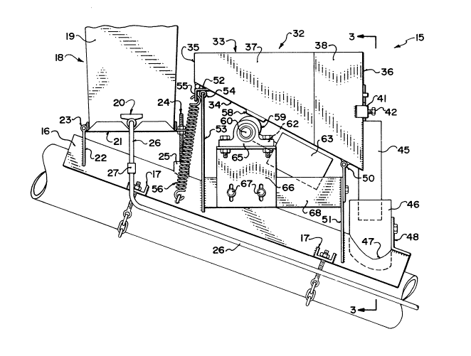
The operators as shown in Figùre 1 comprise an auger generally indicated at 10
including an auger flight 11, an auger tube 12 and a discharge spout 13. A portion of the
flight is exposed at the lower end of the auger tube to grasp the particulate material to be fed
particularly grain nor seeds for transportation through the tube and discharged through the

`A

~306246
-- 6 --

spout 13 into suitable collecting container (not shown). The auger tube is supported upon a
wheel and strut assembly 14 which is shown schematically since this well known to one skilled
in the art.
The auger described above is of course entirely conventional but is modified by
the application thereto of a mixing attachment generally indicated at 15 which is shown in most
detail in Figures 2 and 3.
The attachment 15 comprises a support member 16 in the form of an angle iron
which is arranged with the apex upward and parallel to the axis of the auger tube. The angle
iron can thus be strapped down onto the upper surface of the auger tube by way of two pairs of
lo flanges 17 with the pair being spaced adjacent respective ends of the angle iron 16 with one of
each pair on either side of the angle iron as best shown in Figure 3. A chain connection
extends around the underside of the auger tube so as to strap the angle iron downwardly onto
the auger tube in fixed position. In this way the attachment can be simply applied and
removed without difficulty so the auga can be reverted to conventional use as required.
At an upper end of the support member 16 is provided a first container
- generally indicated at 18 in the form of a liquid tank 19 with a dispensing nozzle 20. The
liquid tank is mounted upon a base frame 21 carried on the support member 16. The base
frame is attached to the support member by a plate 22 which is connected to one end of the
base 21 by hinge 23 allowing some pivotal action. The plate 22 is a flat plate with a V-shaped
20 cut out at its lower edge so that it can extend over the upper surface of the angle iron for
welding thereto as shown. The other end of the base 21 is connected to the support 16 by way
of a screw 24 which is supported on a welded stud 25 carried on the uplper surface of the
support 16. The base 21 has a flange which is clamped between a pair of nuts carried on the
screw 24 so that the height of the flange and thus the base 21 can be adjusted by rotating the
nuts on the screw. In this way the base 21 can be maintained in a horizontal or level condition
regardless of variations in the angle of the auger tube to accommodate different heights of
discharge. The container 19 is preferably a plastic container which is strapped into place on
,'~


,
.~ , ~ . .

- ~306246
-- 7

the base 21 and has a suitable opening at the upper surface for receiving a liquid for discharge
through the spout 20.
A hose line 26 is connected to the spout 20 for receiving the liquid discharged.The hose has a metering valve 27 positioned adjacent its inlet end extends from the metering
valve down the auger tube as shown in Figure 1 to a position below the support 16. At the
lower end of the tube is mounted an inlet bracket 28 which comprises a part cylindrical portion
which wraps around the upper part of the auger tube and a pair of flanges 29 similar to the
flanges 17 so that the half cylindrical portion can be strapped onto the tube at a first position
there on. Within the tube is provided an opening which is preferably the order of one inch in
lo diameter so that liquid discharge from a half inch diameter tube 26 can enter through a right
angle injection nozzle at the connection between the pipe 26 and the bracket 28 as indicated at
30. Liquid from the tank 19 thus runs under gravity from the tank into the auger tube at the
bracket 28 at a rate controlled by the metering valve 27.
Below the first container 18 on the support member 16 is mounted a second
container system indicated at 32. The second container comprises a hopper 33. The hopper
has an inclined lower wall 34 which inclines downwardly from a rear vertical wall 35 to a
front vertical wall 36. The sides of the hopper comprise first portions 37 parallel to each other
and at right angles to the rear wall 35 and inwardly inclined portions 38 so the material as it
runs down the lower wall 34 is converged by the inwardly inclined lower portions 38 toward
the narr~wer front wall 36. The front wall 36 has an opening 39 at the bottom of the front
wall so that material can be discharged through the opening. The opening is controlled by a
slideable gate 40 which can be moved up and down to open and close the opening by sliding
action through a channel member 41 and can be locked in placed by a screw 42 which extends
through the channel member. A gauge is indicated at 43 and is connected to the gate for
sliding action through a loop 44 which acts as guide and also as a marker for the gauge 43.
The opening 39 discharges into a tubular duct 45 which depends downwardly from the front
face 36.


~. .

-` 1306246


A tubular duct 46 of larger diameter is connected to the upper surface of the
support member 16 and projects through an opening 47 formed in the support member 16. An
upwardly extending flange 48 is connected to the tubular duct 46 for vertical adjustment of the
height of the tubular duct 46 so that its lower end is adjustable relative to the outer surface of
the auger tube 12. The tubular duct 45 thus deposits into the larger tubular duct 46 to guide
the particulate material that exits from the container so that it is properly guided to drop into a
circular opening 12A forrned in the upper surface of the auger tube 12.
The lower or front end of the hopper 33 is supported by a hinged connection 50
mounted upon a vertical plate 51 welded on the upper surface of the support member 16. The
rear end of the hopper 33 is supported upon a flange 52 which extends in a horizontal plan
across the rear edge of the lower wall 34. The underside of the flange 52 rests upon a vertical
plate 53 and more particularly upon a rubber or resilient bead 54 carried on the upper edge of
the plate 53. The plate 53 is welded to the upper surface of the support 16 so as to extend
vertically upwardly therefrom. A rear edge of the flange 52 carries a loop 55 which connects
to a spring 56 the other end of which is connected to a a further loop 57 welded on the side of
the support 16. Thus the rear end of the hopper can move upwardly and downwardly and is
resiliently restrained at a lower position by its cooperation with the bead 54 and the spring 56.
It is however free to pivot about the hinge 50.
A striker plate 58 is provided on the under surface of the lower wall 34. The
striker plate 58 is struck by a cam S9 mounted upon a shaft 60 rotatable about an axis
transverse to the lower wall 34. Thus the cam S9 repeatedly engages the striker plate 58 to lift
the striker plate 58 and thus the hopper through a small distance to cause a vibration within the
hopper for each rotation of the shaft 60. The shaft is driven through a right angle gear
reduction system (not shown) which is in turn driven by a shaft 62 and an electric motor 63.
The motor 63 is of the 12 volt variety so that it can be driven by the electrical system of the
auger itself or of a cooperating tractor unit. The shaft 60 is carried in pillow blocks 65
mounted upon a plate 66 which is adjustable vertically by way of screws 67. The screws 67


~ , .
:

t

~306246
g

cooperate with a transverse plate 68 carried on the vertical plates 51 and S3.
Alternative arrangements can be used fir metering the material through the gate
fronn the hopper. In one other example (not shown) a rotating eccentric mounted directly on
the hopper so as to generate vibration without the striking effect, thus reducing noise.
Metering by roller feed can also be used.

In operation an adhesive agent in liquid form is filled into the container 19. Atreatment material in particulate or powder form is applied into the hopper 33. The valve 20 is
then operated to commence the flow of the liquid from the container through the pipe 26 to
lo discharge into the auger tube at a first position adjacent the feed end.
The auger flight is started so the particulate material particularly seeds is
collected from the feed end and carried along the auger tube with discharge through the spout
of the upper end. As the seeds pass the first position, the liquid enters the seeds and is mixed
with the seeds by way of the rotation of the flight as it carries the seeds upwardly toward the
second position which is at the opening 12A where the hopper 33 discharges into the auger
tube. At the second the adhesive agent is already well mixed with the seeds so the powder
when applied into the auger tube onto the seeds mixes with the seeds and adheres to the
adhesive agent. The spacing between the first position where the liquid is applied and the
second position where the powder is applied is arranged to be sufficient (approximately S feet
20 has been found sufficient in practice) to enable full mixing of the liquid with the seeds. The
unit containing the liquid and the powder hopper is positioned thus approximately S or 6 feet
- from the lower end of the auger which is a convenient position for manual operation of the
various part.s
The fesd of the powder material from the hopper is carried out by accuating the
motor 63 which drives the vibration action of the hopper thus causing the material to be
discharged in doses from the hopper through the opening and into the auger tube. The speed
of the feed system can be varied by increasing or decreasing the size of the opening by

`~ ,
,
''

:-


1;~06;~46

-- 10 --

adjusting the gate 40 or can be varied by varying the vibration effect of the hopper. The useof a direct drive motor enables simple adjustment of the speed of the motor to vary the
vibration effect.
The device proposed has particu1ar use for the inoculation of seeds in which theseeds are transported by the auger and the inoculate powder is applied from the hopper 33.
However other uses of this device are possible as follows:
(a3 blending grass seed;
(b) blending granular chemicals with oil seeds;
(c) blending mustard or canola with peas;
(d) blending different lcinds of cereal grain; and
(e) treating all types and varieties of grain.
In some of these cases the liquid i5 not needed so that the valve on the liquid
container simply closed off and only the feed system from the hopper 33 is used to obtain the
mixing effect.
The unit can be readily removed from the auger by unstrapping the support 16
and the liquid dispensing bracket. The exposed holes in the tube can covered by a suitable
temporary patching technique.
Since various modifications can be made in my invention as hereinabove
described, and many apparently widely different embodiments of same made within the spirit
20 and scope of the claims without departing from such spirit and scope, it is intended that all
matter contained in the accompanying specification shall be interpreted as illustrative only and
not in a limiting sense.


',~
,


,

Representative Drawing
A single figure which represents the drawing illustrating the invention.
Administrative Status

For a clearer understanding of the status of the application/patent presented on this page, the site Disclaimer , as well as the definitions for Patent , Administrative Status , Maintenance Fee  and Payment History  should be consulted.

Administrative Status

Title Date
Forecasted Issue Date 1992-08-11
(22) Filed 1989-06-27
(45) Issued 1992-08-11
Deemed Expired 2007-08-13

Abandonment History

There is no abandonment history.

Payment History

Fee Type Anniversary Year Due Date Amount Paid Paid Date
Application Fee $0.00 1989-06-27
Maintenance Fee - Patent - Old Act 2 1994-08-11 $50.00 1994-06-15
Maintenance Fee - Patent - Old Act 3 1995-08-11 $50.00 1995-07-18
Maintenance Fee - Patent - Old Act 4 1996-08-12 $50.00 1996-08-02
Maintenance Fee - Patent - Old Act 5 1997-08-11 $275.00 1997-10-31
Maintenance Fee - Patent - Old Act 6 1998-08-11 $150.00 1998-08-06
Maintenance Fee - Patent - Old Act 7 1999-08-11 $75.00 1999-08-05
Maintenance Fee - Patent - Old Act 8 2000-08-11 $75.00 2000-08-04
Maintenance Fee - Patent - Old Act 9 2001-08-13 $75.00 2001-07-23
Maintenance Fee - Patent - Old Act 10 2002-08-12 $100.00 2002-07-26
Maintenance Fee - Patent - Old Act 11 2003-08-11 $100.00 2003-07-31
Maintenance Fee - Patent - Old Act 12 2004-08-11 $125.00 2004-08-06
Maintenance Fee - Patent - Old Act 13 2005-08-11 $125.00 2005-08-11
Owners on Record

Note: Records showing the ownership history in alphabetical order.

Current Owners on Record
NORTON, R. SCOTT
Past Owners on Record
None
Past Owners that do not appear in the "Owners on Record" listing will appear in other documentation within the application.
Documents

To view selected files, please enter reCAPTCHA code :


To view images, click a link in the Document Description column. To download the documents, select one or more checkboxes in the first column and then click the "Download Selected in PDF format (Zip Archive)" or the "Download Selected as Single PDF" button.

List of published and non-published patent-specific documents on the CPD .

If you have any difficulty accessing content, you can call the Client Service Centre at 1-866-997-1936 or send them an e-mail at CIPO Client Service Centre.


Document
Description 
Date
(yyyy-mm-dd) 
Number of pages   Size of Image (KB) 
Representative Drawing 2000-07-28 1 29
Drawings 1993-11-04 3 65
Claims 1993-11-04 9 416
Abstract 1993-11-04 1 20
Cover Page 1993-11-04 1 14
Description 1993-11-04 10 493
Fees 1997-10-31 1 42
Fees 2005-08-11 1 28
Fees 1996-08-02 1 44
Fees 1995-07-18 1 33
Fees 1994-06-15 1 49