Note: Descriptions are shown in the official language in which they were submitted.
--1--
CONTROLLING ENGINE COOLANT FLO~
AND VALVE ASSEMBLY THEREFOR
Background of the Invention
In vehicles powered by internal combustion
engines of the li~uid cooled type, it is common practice
to circulate engine coolant through an air cooled heat
exchanger, or radiator, for cooling the engine. It is
also common practice to circulate engine coolant through
an air heat exchanger or heater core for provlding
heated air to the vehicle passenger compartment for cold
climate operation of the vehicle.
For many years it has been the practice in
automotive vehicle design, to control the flow of
coolant to the radiator by retarding or blocking flow by
a thermally operated valve, or thermostat, upon cold
engine start-up to enable the engine to reach normal
operating temperature before the liquid coolant is
circulated to the radiator. Such thermostats have
heretofore been operated by differentially expansible
bi-metal actuators, or more recently, expansible wax
pellet charge type actuators for opening the coolant
valve upon the coolant in the engine reaching the
~0 desired operating temperature. When thermostatic valves
of either of the aforementioned types are opened to
permit coolant circulation through the radiator, the
recirculation of cooled liquid in the engine causes the
thermoactuator to severely restrict the flow of coolant
thought the valve. In particular, it has been found
that wax pellet type thermostats operate in cool or.cold
weather with the thermostatic valve only very slightly
open, or almost closed, thereby providing only a
fraction of the flow of which the valve is capable of in
the fully open position.
,
i:
--2--
When a typical automotive engine coolant
thermostat is operated at only a slightly open position,
sludge formed by rust and particles of foundry core sand
from the engine block casting, have been found to
accumulate on the valve and create deposits which thus
prevent the thermostat from completely closing. When
deposits on the thermostatic valve prevent complete
closing thereof, upon cold engine start-up, flow is
permitted through the thermostatic valve immediately and
warm-up of the engine is thus retarded.
In modern passenger automobile engine design,
it has been found that the engine warm-up period must be
kept as short as possible in order to reduce the
inefficiency of the combustion and the resùltant
undesirable exhaust emissions resulting from inefficient
combustion. Thus, it has been desired to provide
control of the liquid coolant in an engine in such a way
as to maximize the engine warm-up process.
However, for a given full load cooling capacity
of an engine/radiator cooling system, it is necessary to
severely restrict or throttle the flow of coolant with
the thermostatic valve in order to prevent the engine
coolant operating temperature from dropping below the
desired level at less than full power or full load
operating condtions. In particular, where the radiator
has the cooling capacity for accommodating full power
vehicle operation in extreme environments such as hot
and humid or desert climates at less than full power and
in moderate climatic conditions, the thermostat will be
required to severely restrict flow to the radiator.
This restriction of coolant flow by the thermostatic
valve has proven to be troublesome in service because of
deposit build-up in the restricted flow position of the
valve.
~i,",~h ~; ~3~35
--3--
Thus, it has long been desired to find a way or
means of controlling engine coolant flow to the radiator
in a manner which would maintain constant operating
temperature in the face of a widely varying engine power
and climatic conditions, and to eliminate the problems
encountered with severe throttling through the
thermostatically controlled valve.
In another aspect of engine coolant
circulation, where the coolant is employed in a heater
core for maintaining passenger compartment comfort in
cold climate operation, it has been typical automotive
design practice to employ a manual control for vehicle
occupant selection of the position of a flow control
valve, typically of the butterfly-type, for altering the
flow of engine coolant through the heater core. In
addition, provisions are usually made for the vehicle
occupant to select from plural settings of a blower
speed control for increasing or decreasing the forced
air circulation from the blower over the heater core.
Where automatic control of passenger compartment
temperature has been desired, typical automotive design
practice has been to employ a vacuum motor to vary the
position of a blend door for mixing refrigerated air
with heated air for controlling the temperature of the
air discharged from the blower plenum to the passenger
compartment. Such control systems have also employed a
blower speed control switch slaved to the vacuum motor
for proportioning heater blower speed with the control
movements of the air blend door in the plenum.
However, it has long been desired to eliminate
mixing heated and refrigerated air to control passenger
compartment temperature because this technique requires
operation of the air conditioning refrigeration
~ - 4 -
compressor to provide a source of cooled air for
tempering the discharge air to the passenger
compartmen~. Thus, it has long been desired to find a
way or means of automatically electrically controlling
the flow of engine coolant to the heater core in order
to enakle automatic modulation of the heater core
temperature instead of providing refrigerated air from
the air conditioning evaporator mixed with the air blo~n
over the heater core in order to provide tempered air to
the passenger compartment.
Accordiny to one aspect of the present invention
there is provided a method of controlling coolant flow
between an internal combustion engine and an air heat
exchanger, the method includes the steps of providing an
electrically operated valve in fluid series flow
arrangement in the circuit of coolant flow between the
engine and the heat exchanger and sensing the
temperature of the coolant in the engine and providing
an electrical signal representative of the sensed
~0 temperature. The sensed temperature signal is compared
with a reference temperature signal, a valve control
signal is generated and the position of the valve is
controlled to alter coolant flow for modulating engine
temperature about the reference temperature. The valve
is opened sufficiently to effect full flow for a small
fraction of the cold engine warm-up interval, and the
valve is flushed of foreign material.
Another aspect of the invention resides in the
method of controlling coolant flow through the exchanger
circuit of an internal combustion engine, the method
including the steps of channeling coolant flow from the
engine through a valving passage to the coolant heat
exchanger and providing a valve in the passage. The
coolant temperature is sensed in the engine. The valve
is opened upon rold engine start-up to permit
substantially full flow therethrough for a brie~
~ -4a -
interval comprising a small fraction of the engine
warm-up period, for cleaning foreign particles from the
valve seating surface. The valve is returned to a
partially open position ~or continued warm-up. The
position of the valve is modulated in response to
changes in the sensed temperature controlling coolant
flow to maintain normal engine operating temperature.
Yet another aspect of the invention resides in a
system for controlling flow o~ coolant in a circuit
lo comprising an internal combustion engine and a heat
exchanger for transferring heat from the engine coolant
to passenger compartment air in a vehicle. The system
includes a heat exchanger means having an inlet and an
outlet which is connected to the engine for coolant flow
therethrough and transducer means operative to sense
temperature in the vehicle passenger compartment, the
transducer means being operative in response to the
sensed temperature to provide an electrical temperature
feedback signal. Alternatively, the transducer means
may be operative to sense the engine coolant jacket
temperature or the temperature of the air in discharge
closely adjacent the heat exchanger means. The system
also includes electrically actuatable valve means with
the inlet thereof receiving heated coolant from the
engine with the outlet of the valve means discharging to
the inlet of the heat exchanger means. The valve means
has a housing means formed of plastic material and
defining integrally therewith a flow passage. The valve
means further has a motor cavity and gear box with a
stepper motor disposed in the cavity with speed reducer
means having an output disposed in the gear box and
driven by the stepper motor. The valve means includes a
rigid pivoted member movable by the speed reducer output
between a closed position preventing ~low thereover and
an open position permitting coolant ~low to the heat
exchanger, the pivoted member having an elastomeric
~J .
~ 4b -
seating surface for prsventing coolant leakage in the
closed position.
A logic and power circuit means is operable in
response to the temperature feedback signal and a
comparison thereof with a reference temperature to
provide a valve actuating signal for actuating the
stepper motor to position the valve member in a
preselect position in response to the comparison and
thereby control coolant flow for modulating the
passenger compartment temperature at the reference
temperature. Alternatively, if the transducer means
senses the temperature of the discharging air of the
heat exchanger, the valve member is positioned in a
preselectad position to control coolant flow for
modulating discharge to air at the reference
temperature. In the event the transducer means senses
the engine coolant jacket temperature, the valve member
is set in a preselected position to control coolant flow
for modulating the engine temperature at the reference
temperature.
Yet a further aspect of the invention resides in
electrically actuated valve assembly for controlling
flow of engine coolant, the valve assembly including a
housing formed of plastic material and integrally
defining a coolant flow passage having an inlet and an
outlet, a motor casing and a gear box. A butterfly
valve member is disposed in the passage between the
inlet and the outlet, the valving member being pivoted
about an axis transverse to the direction of ~low and
operable for pivoted movement between a closed position
and open positions permitting partial or full flow
therethrough. A shaft extends through the wall of the
housing into the passage and is journalled therein for
rotation with respect thereto. The shaft has the end
portion thereof external to the passage including
indicator means extending in a direction generally
~I 3IJ~ j3~
parallel to the butterfly member, the shaft having the
valve member attached thereto for providing the pivotal
movement upon rotation of the shaft. A stepper motor
means is provided which includes speed reducer means
received in the casing, the speed reducer means is
provided in the gear box having power output shaft means
with torque coupling means provided thereon, the torque
coupling means engaging ths external end portion o~ the
shaft for effecting rotation thereof upon the stepper
motor being energized by an electrical control signal.
The present invention provides a unique method of
controlling circulation of engine coolant to a heat
exchanger to maintain the engine at a constant oparating
temperature in the face of extremes o~ power loading and
climatic conditions of vehicle operation. The present
invention provides an electrically actuated
butterfly-type coolant flow valve which has an
elastomeric seating sur~ace for completely sealing the
flow of coolant in the closed position. The present
invention employs a motorized actuator mounted directly
on the valve for varying the position of the butterfly
in response to an electrical control signal. The
control signal is generated by comparison of a
temperature selected from the group consisting of a
engine coolant temperature, heater core discharge air
temperature and vehicle passenger compartment ambient
temperature, and comparing the sensed temperature with a
desired or selected temperature, and the electrical
control signal variation is representative of the
comparison. The control signal energizes the motorized
actuator for controlling the position of the butter~ly
valve to modulate the coolant flow for regulating the
sensed temperature about the reference temperature.
--5--
In one unique aspect of the invention, the
electrically energizable butterfly valve is suddenly
opened to effect full coolant flow for only a fraction
of the cold engine warm-up interval, in order to
provided full flow flushing of the valve to remove
accumulated deposits from the valve seating surfaces and
then re-closed to continue engine warm-up. This sudden
opening and closing provides a unique automatic means of
self-cleaning the coolant flow control valve to prevent
deposit build-up on the valve seating surfaces which can
prevent full closing of the valve and cause an increase
in cold start engine warm-up interval.
The present invention thus provides a unique
and novel control of engine coolant circulation to an
external heat exchanger. The invention provides
electrically controlled modulation of the coolant flow
to regulate engine temperature where the valve is
employed to control flow to the radiator, and enables
electrically controlled modulation of the coolant flow
to a heater core where the valve assembly is employed
for passenger compartment temperature control.
Brief Description of the Dr_wings
Figure 1 is a pictorial schematic of the
control system of the present invention;
Figure 2 is a front elevation view of the valve
assembly of the present invention;
Figure 3 is a top view of the valve assembly of
Figure 2 and,
Figure 4 is a partial section view taken along
section-indicating lines 4-4 of Figure 2.
Figure 5 is a graph of engine temperature
plotted as a function of time from cold engine start.
Figure 6 is a section view taken along
section-indicating lines 6-6 of Figure 4.
$.3
--6~
Detailed Description
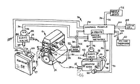
Referring to Figure 1, the control system o~
the present invention, is indicated generally at 10, as
employed in an engine, indicated generally by the
reference character E, having a coolant water outlet 12,
typically from the front of the cylinder head in an
in-line engine, and from the top of the intake manifold
in VEE-type engines for coolant f low through a heat
exchanger circuit and a return from the heat exchanger
to the suction side of the engine water pump P at lnlet
18. The engine E typically has a second coolant outlet
14 from the water pump P for connection to a heater core
circuit and a corresponding ~eturn line 16 to the
section side of the water pump indicated generally by
the reference character ~, which also has a main return
18 to the suction side of the pump.
An engine coolant tap 20 is provided in the
cylinder head for connection to a sensor 22 which, in
the present practice of the invention, is a temperature
transducer providing an electrical signal output through
leads 24, 2S, which is indicative of changes in the
sensed temperature of the coolant and the cylinder head.
The engine water outlet 12 is connected to an
electrically ac~uated coolant valve indicated generally
at 28. The valve assembly 28 includes a motorized
actuator energized through electrical leads 30, 32 by a
suitable control signal as will hereinafter be
described, The outlet of the valve 28 is connected
along conduit 34 to the inlet 35 of the engine heat
exchanger or radiator 36 with the outlet 17 thereof,
connected to the water pump suction line 18 for return
flow in the cooling circuit.
,~
3'~
-- 7
The water pump outlet l~ is connected to the
inlet 43 of a similar electrically actuated valve,
indicated generally at 38, which is energized along
electrical lines 40-42 and which has the outlet 44
s thereof connected to the inlet of a passenger
compartment heater core 46 which has the outlet lS
thereof connected to water pump return line 16.
The heater core has a forced air plenum 48 with
blower S0 connected thereto or directing a ~low of air
across the heater core 46 to the vehicle passenger
compartment upon electrical energization of the blower
leads along 52-54~
The valves 28, ~8 and blower 50 are energized
by a motor driver network 56 which is connected to a
command module 58 which includes a suitable
microprocessor for generating the control logic for the
motor driver network~ The command module receives
inputs from ~he coolant sensor 22 and an in~car
thermi$tor 60 connected to the command module by
electrical leads 62, 64. An optional heater discharge
air transducer 66 may also be employed to provide inputs
to the command module along electrical leads 68, 70,
Alternatively, transducer 66 may be mounted in heater core
outlet 15 to sense the temperature of the ~oolant flow as it
leaves the heater core 46, as shown by the dashed outline in
Figure 1. The command module also receives inputs from a
driver temperature select control 72 connected to the
command module by electrical leads 74, 76.
Referring to Figures 2, 3 and 4, the valve
assembly 28 has a housing 78, pre~erably formed of
su~table temperature resistant plaYtic material. ~he
valve inlet 12 preferably comprises a metal flange 80
adapted for direct connection to the engine water
outlet, which flange is connected to the plastic housing
78 by a suitable clamping band 82.
The valve outlet 34 is adapted for connection
to a suitable flexible hose for connection to the
radiator inlet 35.
~.
.
:~.3~ 9S
--8
Referring to Figure 4, the valving passage 84
has disposed therein a butterfly-type valving member 86
which is rigidly attached to a shaft 88, which is
journalled at one end thereof in the wall of the housing
78, and has the opposite end thereof extending through
the wall of the housing and journalled therein and
sealed thereabout by a suitable 0-ring 90 received in a
boss 92 provided on the housing. The end of shaft 88
extending through boss 92 extends outwardly therefrom
and is bent at right angles thereto and extends toward
the outward end of the housing in generally parallel
relationship thereto as denoted by the reference
character 94 in Figure 4. The end 94 of the valve shaft
is secured to the butterfly 86 in such a manner that
when the valve is in the fully open position, the
portion 94 is generally parallel to the direction of
fluid flow in passage 84.
Referring to Figures 2, 3 and 4, a suitable
motor such as a stepper motor denoted 96 is mounted on
the housing 78, and has a drive pinion 98 connected to
the shaft thereof, which pinion extends into a gear
housing 100 attached to the valve housing 78. The motor
pinion 98 engages a cluster gear 102 which has attached
thereto at the hub thereof, for rotation therewith, a
second pinion 104 which engages a second cluster gear
106, which has attached at its hub an output pinion
108. The output pinion 108 engages a toothed segment of
a sector gear 110 which rotates the output shaft of the
gear box.
Referring to Figure 4, the gear box output
shaft is shown as a hub 112 of sector gear 110, which
hub extends outwardly through the wall of gear housing
100 and preferably has formed in the end thereof a
suitable groove or slot 114. The gear box 100 has a
-~ 3~:i3~S
g
suitable plastic cover plate 116 which is attached to
the box 100 by suitable fasteners such as, for example,
self-tapping screws 118. If desired, the ends of the
shafts or axles for the various gears may be journalled
in bosses or apertures provided in the cover plate 116.
Referring to Figure 4, the groove or slot 114
in the output gear hub 112 has the end 94 of the valve
shaft received therein in torque-transmitting
engagement, such that rotation of the output gear 110
causes a corresponding rotation of the shaft 88. The
end 94 of shaft 88 extends outwardly beyond the end of
the gear box 100 and serves as a visual indicator of the
valve position.
In the presently preferred practice, the gear
box has a speed reduction ratio of 1:158 between the
motor pinion and the sector gear hub 112; however, it
will be understood that other ratios may be employed for
the gear box to provide the desired amount of control
resolution for the valve 28. In the present practice,
the stepper motor rotates at the rate of 80 steps per
second in intervals of 15 central arc per step giving
approximately 1/10 rotation per motor step, at the
valve shaft 88. Also, if desired, the housing for the
motor 96 may be molded integrally with the valve housing
78.
Referring to Figs. 4 and 6, the butterfly 86 is
preferably formed of a steel plate 85 and is coated with
elastomer 87 molded thereover prior to attachment to the
shaft 88 to provide a resilient peripheral seating
surface.
The butterfly 86 is preferably mounted on shaft
88 in a balanced configuration so as to provide equal
force moments about shaft 88 of the dynamic fluid forces
of the coolant flow acting on the surface of the
butterfly 86.
''
.
~ ~ .
~ J~i3~
' --10-
It will be understood that the butterfly-type
valve 28 provides full flow with less than full opening
of the butterfly 86 as is well known in the art. The
valve 28 of the present invention has been found to
provide substantially full flow by rotation of the
butterfly in an amount of 45 from the fully closed
position. In the presently preferred practice, the
motor and gear box provide movement of the butterfly 86
from the fully closed to full flow condition in
approximately seven seconds. The valve assembly 28 of
the present invention may thus be readily moved to any
desired position by appropriate electrical signal to the
steyper motor and is thus sufficiently responsive to
enable the engine coolant flow to be controlled in a
desired manner. This is in contrast to prior thermally
responsive engine thermostats which required a 25
temperature rise in the coolant to provide full opening
of the poppet valve controlling coolant flow. The
control system of the present invention senses coolant
temperature in the engine and compares the sensed
temperature with a driver selected or a desired
predetermined engine coolant temperature and generates a
control signal responsive to the difference to cause the
stepper motor to move the butterfly valve to increase or
decrease coolant flow to bring the sensed temperature to
the same level as the desired temperature.
In the presently preferred practice of the
invention, valve 28 is controlled in accordance with the
following algorithm.
Steps = 1/16 [1.0 (DT - CT) + 8.0 tPT - CT)~
Where DT equals desired temperature
CT equals current temperature
PT equals previous temperature.
:
, ', . : '
., - ~ ' ' ~
.
~I.a~qJ~ S
In the presen~ly preferred practice a sampling
period of three seconds has been found to be
satisfactory for the sensing of PT
In the presently preferred practice, when the
quantity (PT - CT) iS equal to or less than one, the
~ain factor of 8.0 is employed in the above algorithm.
80wever, when the quantity (PT - CT) is greater than
one, but equal to or less than two, a gain factor of 16
is employed When the quantity ( PT - CT) has a value
greater than two, it has been found satisfactory to use
a gain of 32 in the above algorithm.
In another aspect of the invention, the command
module i5 programmed to provide an initial sudden full
open flushing or ~clean sweepU cycle of the valve
immediately upon cold enyine start-up to effect full
openinq of the valve for a small fraction o the engine
warm-up interval. This sudden opening permits maximum
coolant flow therethrough to remove any foreign
particles or build-up o deposits on the valve seatiny
surface and thereby prevent leakage when the valve is in
the fully closed position~ In the presen~ly preferred
practice, the sudden opening of the valve to the fully
open pocition is permitted for generally an interval of
less than 30 seconds after which the valve is returned
to the closed position.
The elimination o leakage in the closed
position enables the present invention to provide faster
warm-up of the engine as compared to the warm-up
interval of a conventional temperature responsive
thermostat. With reference to Figure 5, engine
temperature is plotted as the ordinate and elapsed time
from ini~ial cold engine start is plotted as the
abscissa as found for the present electrically actuated
valve and for prior art ~hermostat when employed in an
1.3'~ 5
engine having a displacement o~ l~ss th~n t},ree (3)
liters. From the plot of Figure 5, it will be sec~n that
the present invention provides full engine warm-up in
about 40% of the time required for that of a prior art
thermostat.
Referring now to Figure 1, the valve 38
employed to control flow to the heater core 46 is
similar to valve ~8 except the housing 78 is arranged
have a straight valviny passage and the metal mounting
flange is omitted for in-line i.nstallation in the
flexible hose from water pump outlet 14 to the inlet 4
of the valving 38. Valve 38 is otherwise structurally
and functionally similar to valve 28 and a separate
illustration of valve 38 is omitted for the sake of
brevity~
The valve 38 is controlled by a control signal
generated by comparing the output of the in-car
thermistor 60 with a selected temperature input from
driver selec~ 7~ to move the position of the.butterfly
in valve 38 to increase or decrease coolant flow to the
heater core 46 to regulate passenger compartment
temperature about a level represented by the control
selection of the driver.
In fully automatic temperature control systems,
2s the optional transducer 66 senses the temperature of air
blown over the heater core 46 by the flow of air forced
through plenum 48 by blower 50 as it is discharged into
the vehicle passenger compartment or coolant exiting heater
core 46. Temperature of the heated air discharged to the
passenger compartment or heater coolant discharge is
compared with the temperature signal from the in-car
thermistor 60 to provide a control signal to the valve
38 calling for increased or decreased coolant flow to
the heater core to modulate the passenger compartment
temperature about a fixed temperature signal provided by
the driver temperature select control 72.
- 13 -
For the simplest system the command module 5~ provides a signal
to the motor driver 56 such that the motor for valve 38 is
stepped in accordance with the algorithm.
steps = 1~16 [KD (DT ~ CT) f Kp (PT CT)]
Where KD is typically equal to one (1) and Kp typically has a
value of twenty (20), and where DT i5 the desired temperature
or temperature set by driver select 72, CT is the current or
latest sampling of in-car thermistor 60, PT is the previous
10 sampling of thermistor 60 with a sampling period of preferably
five (5) seconds, with a step speed o~ preferably eighty (80)
Hertz and a gate size of plus or minus two-tenths of one degree
Centigrade (+ .2 C).
15 For a more sensitive control system, the optional transducer 66
is employed to heater core discharge air temperature, as shown
in solid outline in Fiqure 1, and the motor for valve 38 is
stepped in accordance with the algorithm:
Steps = 1/16 [KD (3T ~ cT) + Kp ~PT T)]
HAT
whexe KD, Kp, DT, CT and PT are as described above and where
HAT is the output o~ optional sensor 66 sensing heater core air
discharge. In another more sensitive version of the invention
25 control system, the optional sensor 66 is employed in the
position shown in dashed outline in Figure 1 to sense heater
core coolant temperature returning to the water pump. In this
latter version of the control system, the control signal to the
motor for valve 38 is in accordance with the following
30 algorithm:
Steps = 1/16 ~KD (DT ~ CT) + ~P (PT ~ CT)~
HIT ~ HOT
35 where KD, Kp, DT, CT and PT are as described above, HIT is the
temperature of the coolant entering the heater core as measured
by the signal from transducer 22; and, HOT is the heater core
coolant outlet temperature as sensed by transducer 66.
If desired, the command module may also be
programmed to similarly increase or decrease the speed
of the blower 50 in addition to increasing or decreasing
coolant flow to the heater core to provide faster
response of the system to changes in ambient passenger
compartment conditions.
In another aspect of the invention, an electric
motor 1~0 is employed for driving a radiator fan 122 and
the motor 120 is connected via leads 124l 126 to the
command module. Motor 120 is energized by module 58 ~or
forcing air flow oYer the radiator when the coolant
sensor 2~ indicates that the maximum allowable engine
temperature has been reached.
The present invention thus provides a novel
electrically controlled butterfly valve for controlling
engine coolant flow to a heat exchanger. In one aspect,
the valve is employed as an engine water outlet valve
28, In another aspect, the valve is as the heater core
inlet valve 3B. In the embodiment 28, the housing of
the valve is arranged or direct attachment to the
engine water outlet; and, in the embodiment 38 the valve
housing is of the straight through type for in-line
connection. The electrically operated butterfly valve
of the present invention, either form 2B or 38, provîdes
a unique assembly of, motor-actuator and valve and which
provides for external visual indication of the position
of the butterfly valve in the event of malfunction to
facilitate diagnosis of the failure cause.
The control system of the present invention not
only provides for automatic variation in coolant 10w
through the radiator to regulate the engine temperature
about a desired ~alue, but enables the coolant flow to
be controlled independently of the engine temperature.
The invention control system enables an initial sudden
t;3~3~
- 15 -
opening and closing of the valve during engine warm-up
to provide for flushing and removal of deposits to
prevent leakage when the valve is closed. The unique
construction of the valve prevents leakage in the closed
position to enable ~aster cold-start engine warm-up and
the consequent reduction in undesired exhaust emissions.
Where the valve is employed to control
temperature regulation of the passenger compartment by
controlling coolant flow to the heater core
independently of the speed of the heater blower.
However~ if desired, the blower speed may be
automatically controlled to increase the response of the
system to changes in the passenger compartment
temperature.
In the automatic mode for control of passenger
compartment temperature, the control system generates a
Control signal for the valve 38 based upon signal inputs
indicative of heater core blower discharge air
temperature, in-car thermistor sensed temperature and a
signal from the driver temperature select control.
In another variant, the driver temperature
select control may also include a function for selecting
normal or increased engine temperature operation. This
mode provides the vehicle operator with a means of
raising the coolant temperature in the engine for
purposes of increasing heater core temperature for
providing faster warming of the passenger compartment.
Increasing the temperature of the heater core also
increases the temperature of discharge air diverted for
the defrost function.
Although the invention has hereinabove been
described with respect to the illustrated embodiments,
it will be understood that the invention is capable of
modification and variation and is limited only by the
following claims.
.