Note: Descriptions are shown in the official language in which they were submitted.
24742-44
The present invention relates to a three-way valve for
distributing or reswitching volumetric flows in bivalent heating
systems or heat storage devices. Such a valve consists of a
valve housing that incorporates an inlet and two outlets, and a
double valve insert, by means o-f which it is possible to connect
selectively either of the two outlets with the inlet, the valve
shaft that retains the two valve bodies being axially adjustable
by means of an adjusting element.
Three-way valves of this type, known up to the present,
have a Eixed inlet, a first outlet that is coaxial with this,
and a second outlet that is at right-angles to the first. The
medium that flows through the valve assembly is diverted from
one to the other outlet depending on the setting of the valve
shaft. As an example, a two-point controller and controls with
an electro-thermal system are used to control these valves. The
straight throughput is thus closed when no current is flowing
and the connection that is opposite the adjusting drive is
fully open, the converse being true when current is flowing in
the system. It is also possible to use continuous-action
controllers to operate the valve shaft, these usually being
proportional controllers that do not use secondary energy and
that also provide intermediate positions. When -the temperature
at the sensor rises, the direct passage is closed, and the branch
passage is opened.
In the case of such valves, it has been found to be
disadvantageous that -the outlets are fixed, since this causes
difficulties for the installer when such valves are being put in
place.
24742-44
Proceeding from the prior art, it is the task of the
present invention to create a three-way valve of this type, which
is oE simple construction and which simplifies installation, in
particular integration into pipe systems.
The present invention provides a thxee-way valve,
especially for a bivalent hea-ting plan-t or hea-t storage comprising:
a valve housing surrounding an axis of the valve housing and
formed with an inlet at a fixed location on said housing extending
transversely to said axis and opening into a valve chamber formed
in said housing; a pair of outlet fittings extending transversely
to said axis and communicating with said cham~er on opposite
axial sides thereof, each of said outlet fittings being rotatable
about said axis for establishing various relative angular posi-
tions of said fi-ttings relative to one another and to said inlet
about said axis, each of said outlet fittings being formed on an
annular compartment surrounding said housing and communicating
with said chamber through a plurality of radial openings ~ormed
in said housing; respective axially displaceable valve members
spaced apart along said axis and respectively positioned to
alternately block communication between said inlet and one of said
outlet fittings while communicating between the other outlet
fitting and said inlet, and a s-tem extending along said axis and
connec-ting said valve members for joint axial displacement into
a double-valve assembly; and means for axially shifting said
assembly relative to said housing.
As a resul-t of this arrangement and configuration, it
- .,5
24742-44
is -- in principle -- possible to connect the inlet, which
continues to be fixed, with the corresponding connector line,
and to move each of the outlet fittings on the body housing, by
separate rotation, to an orientation that is convenient for making
further connections to other lines and the like.
- 2a -
~ 24742 ~1
In addition, it is preferred that the annular chambers
including the connec-tors be secured to the housing by means o~
retainer rings, so as to be immovable axially but able to rotate.
It is especially preferred that the housing incorporates
a channel, through which the valve stem passes, approximately
centrally between the outlet connectors~ into which channel the
connector that forms the inlet opens, and which can be connected
to a chambers arranged above and below the channel in the
direction of the axis of the housing, through respective openings
that can be closed off by one of the valves, said chambers
incorporating the radial through-flow ports that are enclosed by
the annular chambers of the connectors.
An embodiment of the present invention is described
below on the basis of the drawing appended hereto, which shows a
three-way valve in cross-section.
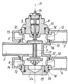
The three-way valve comprises, essentially, a valve
housing 1, with an inlet 2 and two outlets 3~ 4. Within the
valve housing 1 there is a double valve insert that comprises
the valve bodies 5, 6 that are mounted on a common valve shaft 7.
The double valve insert operates in conjunction with corresponding
valve seats, so that the inlet 2 can be connected alternataly with
the outlet 3 or the outlet 4. The valve shaft 7 is screwed into
the housing 1 through a cap 8 and is spring-loaded by the coil
spring 9. An operating end 10 of the valve shaft protrudes to
the outside of the housing, or from the cap 8, and this can be
operated by means of a suitable adjusting element. With the valve
shaft 7 pushed clown, as is shown in the drawing, the inlet 2 is
- 4 ~
2~742-44
connected to the outlet 4 f whereas when the valve shaft 7 is
moved relatively upwards under the action of the spring 9, the
inlet 2 is connected to the outlet 3.
According to the present invention~ the inlet 2 and
the outlets 3 and ~ are oriented transversely, in particular at
right angles, to the valve shaft, the inlet being formed in the
manner known per se by a connector piece that is joined rigidly
to the housing 1, and the outlets 3, 4 are formed by connectors
that are rotatable about the midline axis 11 of -the housing. The
connectors incorporate annular chambers 13, 14 that enclose the
radial through-flow ports 12 in the housing walls so as to seal
them, and the associated connector piece protrudes radially from
each of these. The annular chambers are sealed by means of
O-rings 15, and held bv retaining rings 16 so as to be immovable
axially but be able to rotate. The housing 1 incorporates a
channel 17 through which the valve shaft 7 passes r said channel
being located approximately centrally between the connectors
(outlets 3, 4), the connector that forms the inlet 2 opening into
this channel. The channel 17 can be connected through an opening,
which can be closed off by one of the two valves 5, 6, to a
chamber 18, 19, respectively, arranged above or below the channel
17. These chambers incorporate the radial ports 12 that are
enclosed by the annular chambers 13, 14. The valve is so
assembled that -the annular chambers 14 is ins-talled onto the
tube-like seating elements of the housing 1 that are located
above and below in the drawing, and then held in position by
installing the retaining rings 16. Then, the cap 8 with the
valve body 5 can be screwed into the appropriate receptacle from
247~2-44
above. Next, the valve body 6 is screwed into position through
the lower access opening and the cap 20 is screwed on so as to
provide an effective seal. The movement of the outlets 3, 4 is
not hindered by the inlet 2, since the planes of rotation of the
inlets 3, 4 lie axially beyond the region that is taken up by
the inlet 2.
The present invention is not confined to the embodiment
shown, but can vary in many respects within the scope of the
claims.