Note: Descriptions are shown in the official language in which they were submitted.
~ ~6 ~
OPTICAL POS_TION ENSOR
The present invention relates to an optical position sensor,
and more particularly, it relates to an optical sensor able to
measure the position of a movable body with respect to a fixed
reference element, said movable body and said fixed reference
element being remote from the generator of the optical signal,
and in which the displacement of the remote movable body is
converted into a phase variation of the optical signal
transmitted to the remote area through an optical fiber.
B~CKGROUND OF THE INVENTION
~s known, there is apparatus which, for its operation,
requires a determination of the displacement of movable bodies
with respect to fixed reference elements situated in zones
distant from the apparatus and in environments where the
atmospheric conditions are severe and changeable. For example,
the central control unit of an aircraft, situated in the pilot
compartment, must know the position of the ailerons, and it is
evident that the environmental conditions around the aircraft,
such as temperature, pressure, humidity and so on, may be
extremely variable.
It is also known that the most reliable instruments to
measure such displacements are those of the optical type which,
besides being simple and compact, have a low attenuation of the
signal and have an immunity to electromagnetic disturbances.
Further, optical position sensors are known, which make use
of a local, amplitude modulated monochromatic light source which,
through an optical fiber, is conveyed to the remote area where
the movable body whose position is to be determined is located.
In said sensors, the modulated light exits from the free end of
the optical fiber, strikes the surface of the movable body and is
30 reflected into the optical fiber.
13~
In this way, the light reflected by the movable body is
phase displaced by an angle which is peoportional to the distance
between the movable body and the end of the optical Eiber. The
phase displaced light transits the optical fiber again and is
locally compared to the modulating signal. In this way, the
phase displacement of the reflected light with respect to the
modulating signal, and therefore, the position of the movable
body, is determined.
The above-described optical sensors have a substantial
drawback in that the phase displacement measured between the
reflected light and the modulating signal does not represent only
the position oE the remote movable body, but also involves all of
the undesirable phase variations induced by the environmental
conditions where the optical fiber is operating.
In fact, such variations in temperature, pressure, humidity
and so on, together with the length Oe the optical fiber, which
can be some tens of meters, induce variations in the transmission
characteristics of the optical fiber, which result in phase
displacement of the optical signal not due solely to the position
of the movable body. In particular, when the displacements to be
measured are very small, of the order of some tens of microns,
the false or environmental phase displacements induced by the
ambient can distort the measurement of the position of the remote
body.
BRIEF DESCRIPTION _ THE INVENTION_
It is one object of the present invention to overcome the
disadvanta~es of the prior art sensor and to provide an optical
sensor able to determine the position of a remote movable body in
which the false phase variations induced by the variations of the
environmental conditions where the optical fiber operates, are
compensated.
~3~fi~
67487-373
To achleve such obje~t, the present invention
provides an optical positlon sensor for measuring the positlon
of a movable body, said sensor comprising:
first and second generators ~or respectively generating an
optical, monochromatic measuring signal of a first wavelength
and an optical, monochromatic reference signal of a second
wavelength;
modulating means connected to said generators for
modulating the optical signal outputs of said generators with a
radio frequency signal to thereby provide a modulated reference
signal and a modulated measuring signal;
an optical fiber coupled to said generators for
transmitting the modulated reference signal and the modulated
measuring signal to a point spaced from said yenerators;
transmitting and reflecting means at said point coupled to
said optical flber for transmitting said modulated measuring
signal to a body, the position of which is to be measured, and
for receiving modulated measuring signal energy reflected from
said body and directing said energy into said optical fiber,
said transmitting and reflecting means also reflecting said
modula~ted reference signal at said point; and
phase comparing means coupled to said optical fiber for
determining the phase difference between the modulating signal
on the reflected measuring signal energy and the modulating
signal on the reference signal and thereby determining the
distance of the body from said transmitting and reflecting
means.
B~I~F DESCRIPTION OF TH~ DR~WING
The objects and advantages of the invention will be
apparent from the ~ollowing detailed description of the
preferred embodiment of the invention which should be
~L3(:~6~
674~7-373
considered in conjuncti.on with the accompanying drawing which
is a block diagram of the preferred embodiment of the
invention.
DETAIL~D D~CRIPTION OF THE INVENTION
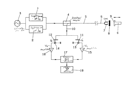
The drawing illus~rates a source 1 of monochroma~ic
light having a wave length ~1' which generates a so-called
"reference" optical signal, and a source 2 of monochromatic
light, having a different wave length ~2 which generates a so-
called "measuriny" optical signal. The meaning of such terms
will be more clearly understood in the course of the
description.
The optical measuring signal ~2 and the optical
reference signal ~1 are amplitude modulated by a radio-
frequency electric signal, e.g. having a frequency in the
gigahertz range, generated by a modulating means in the form of
a modulating signal generator 3. The amplitude modulated
measuring signal ~2 and the amplitude modulated reference
signal ~ 1 are sent to the common input of a directional
coupler 4. An optical fiber 5 extends from the output of the
directional coupler 4 to a remote point or area adjacent to a
movable body 6, the displacements of
13~6S;~'~
which are to be measured.
The remote end of the optical Eiber 5 is connected
for transmitting the measuring signal to the movable body 6,
~or receiving measuring signal energy reflected ~rom the body 6
and directing it into the optical ~iber 5 and ~or reflecting the
reference signal. Such means includes a lens 7, used to focus
the light beam coming from the optical fiber 5, and a semi-
reflecting mirror 8 which acts as an optical filter and allows
the full passage of the optical measuring signal~ 2 and reflects
completely the optical reference signal ~ 1
The movable body 6 has a surface 9, facing the semi-
reflecting mirror ~, which reflects substantially all the light
directed thereon.
An optical fiber lO extends from another output of the
directional coupler and to two semi-reflecting mirrors 11 and 12.
The semi-reflecting mirror ll acts as an optical filter, allowing
the full passage of the optical re~erence signal ~1 and blocking
completely the optical measuring signal ~2. Analogously, the
semi-reflecting mirror 12 acts as an optical filter, allowing the
full passage of the optical measuring signal ~ 2 and blocking
completely the reference signal ~l
Two photodiodes 13 and 14 are disposed to receive light
passing through the semi-reflecting mirrors ll and 12, and they
convert the optical signals into electric signals. The electric
signals of the two photodiodes 13 and 14 are respectively
amplified by two operational amplifiers 15 and 16 and are then
sent to the two inputs of a phase comparator 17. ~ variable phase
shifter 18 is also connected to the phase comparator 17.
In operation, the amplitude modulated measuring signal ~2
and reference signal ~ l pass through the directional coupler 4
without being attenuated and, after having been transmitted
through the optical fiber 5, along its whole length, reach the
13~?6~
remote area where the semi-reflecting mirror 8 acts as a fixed
reference for the movable body 6. The optical reEerence signal
~ 1 is completely reflected by mirror 8 and is therefore
reflected exactly at the position of the fixed reference. On the
contrary, the optical measuring signal ~ 2 passes completely
through mirror 8, strikes the reflecting facing surface 9 of ~he
movable body 6 and is reflected to the mirror ~ and by way of the
focusing lens 7 re-enters the optical fiber 5.
In this to-and-from travel with respect to the fixed
reference mirror 8, the optical measuring signal~ 2 has a phase
displacement with respect to the optical reference signal~ 1'
which is proportional to the distance existing between the fixed
reEerence mirror 8 and the facing surface 9 of the movable body
6.
Consequently, the phase displacement between the reflected
reference signal ~1 and the reflected measuring signal
~ 2 represents the distance of the movable body 6 from the
fixed reference mirror 8.
The reflected optical signals, namely, the reference signal
~'1 of known phase, and the measur ~ signal ~'2~ shifted with
respect to the reference signal, are transmitted through the
optical fiber 5 to the directional coupler 4 where they are
directed to the optical fiber 10. The semi-reflecting mirrors
11 and 12 separate the two reflected optical signals ~'l and
A~ allowing the only passage of the measuring signal ~'2 and
the reference signal ~'1' respectively.
Photodiodes 13 and 14 convert the reflected optical
reference signal ~f 1 and measuring signal ~'2 into two electrical
signals vl and v2, which have the same frequency as the
modulating electric signal and which maintain the same phase
relation of the reflected optical signals. The operational
amplifiers 15 and 1~ amplify the electric signals vl and v2 and
l~ir~Z~
supply them to ~he phase comparator 17 which ~easures the phase
displacement between the two e]ec~ric signals vl and v2, such
phase displacement corresponding to the distance of the movable
body ~ from the fixed reference ~irror 8.
The variable phase shifter 18 is used to adjust the phase
comparator 17. ~ signal from the pnase comparator indicating the
distance of the body 6 from the mirror 8 can then start when the
body 6 deviates from a predetermined position and be supplied to
a circuit (not shown) controlling the position of the movable
body 6.
The described sensor is able to determine the axial position
of a movable body with respect to a fixed reference. Moreover,
by simple modiEications apparent to those skilled in the art, it
can also determine the angular position of a revolving shaft.
From the foregoing description, it is clear that the optical
sensor forming the object of the present invention accomplishes
the object of compensating the false phase variations of the
optical signal measuring the position of the movable body caused
by the variations in the environmental conditions. In fact, when
these variations take place, the optical fiber changes its
transmission characteristics and induces exactly the same phase
displacements on both the modulated optical measuring signal and
modulated reference signal, so that their phase difference is
always and solely that due to the position of the movable body.
In other words, in the conventional optical sensors the
reference signal is represented by the electric signal of the
modulator and remains "fixedl', whereas the optical signal which
measures the position of the movable body, by travelling along
the optical fiber, is influenced by the interferiny phase
variations. On the contrary, in the optical sensor accor~ing to
the present invention, an optical reference signal is generated
which, travelling together with the optical signal which measures
13~i5;;~4
the position of the movable body, is subjected to the same
variations to which the measuring signal is subjected so that,
when the phase diffecence is eEfected, the interfering phase
displacements are compensated and therefore eliminated.
Although pre-Eerred embodiments o~ the present invention have
been described and illustrated, it will be apparent to those
skilled in the art that various modifications may be made without
departing from the principles of the invention.