Note: Descriptions are shown in the official language in which they were submitted.
~ 3~ 6 ~ ~
SXRVICE STATION FOR IN~-J~T PRINTER
:~ ~ TECHNICAL FXELD
The pre~ent invention relates to ~nk-Jet prl~ter~,
and, ~ore part1cularly, to ~ subassembly in such print-
ers known as a ~erY-lce ~tation.
ACKGROUND ART
Servlce ~tatlo~ in ~k-Jet prlnter~ are l~tended
to ~ai~tain a ther~al ink-~et prlnthead in ~ood workln~
: order Por the s~rv~ce llfe of the prlnthead. As 1~
well-~nown to those ~killed in thls art, the printhead
i8 fcrmed as part of a prlntin~ cartridee. The c~r-
tridge co~tains A reservolr of ink, and the printhcad
conta~ns ~n a~sembly of pacsa~eway~, ~lr~ ele~ent6
~resi~tors) ~d nozzles ~or ~rl~y ~rop~ets ~f ink
toward a prlnt~n~ ~edlu~, such as paper.
: Dur~n~ the cour~e o oper~tlon, lt is possible for
; nozzles to become clogge~ wlth lnk and ~or bubbles ~
air to be trapped ln such a ~a~er as ~o~interfere with
the oorrect operation of the prlnthead. A~so, lt 1
~deslred to prevent co~a~i~ant~, ~uch ~s p~per ~u6t,
from affectin~ the operatlon of th~ nozzl~s ~n~ to
event ~nk fro~ dryln~ in the nozzl~s when the pr~nt-
:~ : 25 hea~ ls at r~st. Flnally, lt 18 ~eslred ~o ~lear out
oft vl~cous plu~6 o~ ~nk, ~hlch ~ay for~ while the
:
.
13C~ 7
printhead i5 at rest. This should be done prior to
initiation of printing, to ~nsure that all nozzles in
the orifice plate of the printhead are firing properly.
A service station can address the aforementioned
problems and requirements. While service stations are
not ~Q~ se novel in thermal ink-jet printing, it is a
goal to provide a service station with easy operation
which maximizes a number of functions in a minimum of
space. The preferred service station has a number of
functions, including:
1. clear cloggsd nozsles and remove bubbles;
2. cover nozzles when the printhead i~ not in use
tQ prevent contamination thereof;
3. prevent ink from dryinq out in the nozzles
when the printhead is not in use:
4. wipe contaminants picked up during printing
off of nozzles; and
5. provide a location to fire nozzles into for
clearing out the soft viscous plugs of ink.
DISCLOSU~ OF INVENTION
In accordance with an aspect of the invention, a
service station for use in an ink-jet printer compris~s:
(a) pump means for priming the printhead,
(b) a sled to actuate the service station and
including means to seal the printhead, and
(c) wiping means for cleaning the printhead.
Use of a fixed wiper reduces the number of parts
otherwise required to clean the printhead. Use of a
sled eliminates solenoids. The sled is sel~-actuating,
and re~uires no external control, other than through the
action o~ the carriage motor which controls the motion
of the carriage supporting the cartridge. Use of a ramp
in conjunction with the sled permits positive sealing of
the printhead with a cap and eliminates sliding of the
cap across the oxifice plate of the printhead.
B
, ~
Other aspects of this invention are as follows:
A service station for use in an ink-jet printer,
the printer including a bidirectionally movable carriage
supporting in secured alignment ~ print cartridge having
a printhead for printing onto a print medium, the
carriage being driven by a controlled motor, the service
station being fixed at one end of travel o~ the print
carriage and comprising:
(a) pump means for priming the printhead:
(b) a sled to actuate the service ~tation and
having means to seal the printhead;
(c) wiping means for cleaning the printhead;
(d) said sled including cap means for sealing the
printhead nozzles;
(e) said cap means being maintained on a cap
chamber supported on said sled to which said pump means
is operatively connected;
(f) said sled being movably supported on a ramp
and being provided with engageable means associated with
: 20 the carriage such that upon engagement by motion of the
carriage: and
(g) said sled moving toward along said ramp to
seal the printhead nozzles with said cap means.
: A service station for use in an ink-jet printer,
the printer including a bi-directionally movable
carriage supporting in secured alignment a print
cartridge having a printhead for printing onto a print
medium, the carriage being driven by a controll2d motor,
the service station being fixed at one end of travel of
the print carriage and compriæing:
(a) pump means for priming the printhead:
(b) a sled to actuate the service station and
having means to seal the printhead;
(c) wipiny means ~or clearing the printhead;
(d) said sled inclllding cap means for sealing the
printhead nozzles;
B
3~:~3~637
(e~ said cap means being maintained on a cap
chamber supported on said sled to which said pump means
is operatively connected; and
(f) said wiping means being mounted on a wiper
bracket and being adapted to wipe debris from said
printhead during movement of the carriage into the
service station.
A service station for use in a printer having a
carriage to support a cartridyé, the cartridge including
a printhead having nozzles for diffusing ink, the
service station comprising:
(a) means for wiping residues off of the
printhead;
(b) said wiping means beiny fixed at one end of
travel of the carriag~;
(c~ sled means connected to said wiping means for
capping the printhead ~y surrounding th~ printh~ad
nozzles;
(d) said sled means being actuated by the carriage
when the carriage moves to its end of travel position;
and
(e) pump means connected to said sled means for
priming the printhead.
A method for using a service station in a printer
having a carriage supporting a cartridge, the cartridge
including a printhead having nozzles for diffusing ink,
the method comprising the steps of:
(a) wiping residues off of the printhead;
(b) fixing said wiping means at one end of travel
o~ the carriage:
(c) connecting sled means to wiping means for
capping the printhead by surrounding the printhead
nozzles;
(d) actuating said sled means by the carriage when
the carriage moves to its end of travel position; and
(e) connecting pump m~ans to said sled means for
priming the printhead.
~ .
6~
3b
BRIEF DESCRIPTION OF THE DR~WINGS
FIG. 1 is a front elevational view, partly in
section, of an assembled service station in accordance
with the invention;
FIG. 2a is a front elevational view, partly
exploded, of a peristaltic pump in accsrdance with the
invention;
FIG. 2b is a top plan view of a portion of the
peristaltic pump of FIG. 2a;
FIG. 2c is a detail of a portion of the rollPr used
in the peristaltic pump;
FIG. 3a is a front elevational view, partly in
section, of a portion of the sled subassembly of the
service station of the invention;
FIG. 3b is a front elevational view, partly in
section, of the sled just ater engagement thereof by
the carriage and prior to capping of the printhead;
FIG. 3c is a view similar to that of FIG. 3b, but
of the sled and carriage subsaquent to capping of the
printhead;
FIG. 4a is a top plan view of the wiper bracket of
the service station assembly;
FIG. 4b is a front elevational view of the wiper
bracket; and
FIG. 4c is a cross-sectional view taken alony the
line 4-4 o~ FIG. 4a.
~ ~ )3 ~ .
~3~ ~3~
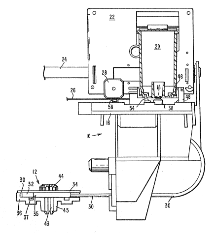
BEST MODES POR CARRYINt~ OIJT T~E INV~NT~ON
Ref errln51 n~w to 'che ~2rawinSI~ ~herel~ ce nu~er-
I!~18 of referencc ~esl5~nate ll~c~ ele~n~nt~ throu~hout, an
~6~emble~1 ~ervlce 6tatls~n 10 18 depi~tetl. The ~ervlce
ætati2n 10 co~prl~ec a perl~;tæltic pump, denote~ ener-
~lly ~t 12, a 01ed 1~, and ~ wiper br~cket 16. The
~servlce ~it~tlon 10 1~ ~hown ln po~t~on cappin~
pr~nthead lB of a pen cartrl~ e 20.
The ~erv~6e ~tat~on 10 ~ro~ ls~ re3;~on ~t one
end o~ the b~ rect~Lonal ~ove~ent of ~ carrlaçle 22,
w~lch hol~ls the o~rtrld~e 20 ~n locke~ ~li~en~. The
c~rrl~7e 22 1~ ~oved bl~irec~on~lly ~los~ lde rod
2~, tyE~lcally by ~eans of ~ belt (not ~hown3 D coDn~oted
~5 to ~ ollrria~e ~otor ~nolt shown), coa~trolled by ~ ~lcre~-
proce~or (not ~hc~wn). The~ tter ole~ent~ arc COIl-
.~ ventlonal ~n the ~rt ~nd hence ~!lo not for~ ~ part of
thl~ invention.
~he . arrl~sle 22, wh~ch can r~tate ~bout th~ trulde
20 rod 2~ ur~ed. a~;aln6t ~he ~ur2ce of ~ paper tJuide26 by vlrtue o~ ~t~ own wel~ht, due to of~et po8~t~0n-
ln5~ (center of $;~ravlty) of the c~rr~e on the ~Front
tsi~le o~ ~he ~ulde a~o~l. A low frlctlon ~p~er 2B c:on
t~cto the paper ~ e surf~ce ~ keep~ the ~rln 42ad
25 1~ ~p~ced the appropr~ate ~ t~nce ~ro~ the pr~nt ~e~
u~ Inot ~hown). In the ~rr~ emenlt t5epicted in FIG. 1,
the p~nt DleRlu~n woul~ be tc the l~t of the ~erY~ce
~t~tlon 10, n~r~aI- to the pl~e of tbe ~lrawlng. Th~
3spacer 28 ~aay be a ~sep3r~te ~?~ece a8 ~ho~m lr the dr~w-
30 ln~ or 8 llaoltled-~n fse~ture o~ ~ae ~r~r~ ae.
Th~ ~erl~t~ltlc pu~p 12 co~lp:rl8e8 la tubo ~0 ~ ~1
rl~ller 32, a~!l a pu~p bo~y ~. A~ ~er~ ore clearly In
FIG . 2~, the per~taltlc pu~p prlllcgple ~ ~hl~h ~Ls ~:on-
v~ntlor~al ~n 'che ~art, ~orks by ~sgueez~na the tube 30
13~ 37
between the roller 32 and a wall 36. Advanta5Teously,
the wall 36 may be Dlolded ~nto the chassls of the
prlnter. As used herein, the chassis con~tltute~ the
frame of the printer.
The roller 32 i8 provided with an a~cial hub 35,
whlch r {de 11l track 3? vf the pump body 34 .
The sgueeze polnt of the pump 12 ~ ~aoved ~lonS~ a
por'clon of t}-e length o the tube 30. In 80 dolng, a
pressure diffea:ential can be created to ef~ect the
10 prl~ing operat~ons on the prlnthead.
~ t wlll be rloted that the pu~p 12 uses only one
roller 32, rather than the ~onventional three rollers.
Becau~e the tube ~0 is only sque!ezed by the roller 32
over 210'' o ~otlon, the pump allows the sy~tem to be
15 vented wlthout ul31n~J an ~xtra p7~rt, ~ucn ~?~ a ~olenoi~
ventln~ valve tled ~nto the tslbing, as l~s com~only done
1n ~che pr~or art . The conf l~uration o~ the invention
allows the prlnthead la to vent to atmox~phere ~s lt
caps (dlscu~sed ln ureater detall below), preventln~7 a
20 pressure r1se El5 the cap collapses (Ree FIGS. 3b-c).
~ven a 6mall pre~sure ri~e when capp~n~ ic intolerable
becau~e ît can forc2 bubbles of air up into the prlnt-
head 1~.
The use of one roller 32 al~;o permi~s the tublng
25 30 to relax between rollln~. Cor~equently, the tubing
30 will A0~ çJet dragged into the pUDlp 12 during opera-
tion thereof, and the tubing will not tal~e a co~pres-
slon s~t.
P.~ 6een ln FIG. 2a, one end of t~le tubinç7 30 is
30 ~ttached to the bot'com o~ a cap cha~ber 38. T~e sther
end o~ the tublnçJ 30 ter~lnate6 ~ ree space, po61-
t~oned over an absorber pad ~not 8hown). Tbe ab~orber
pad 16 used 8 a holdinS7 ve88@1 whlle the lnk evE~po-
rat~6 into the ~lr.
~3~663~
The vent t~ atmosphere ls achieved by use of long
tube 30 hav~ng a small lnslde dlameter, about 0.030 to
0.060 lnch ID. Because of ~he ~;~all lns1de Cll~neter,
diffuslon 1~ very E~low, yl~ldlnçJ an effectlv~ v~por
seal while ~;tlll allc>wing the cap ch23mber 38 to be
vented to atms~;phere. Thls unique aspect o$' ~he con-
fi~urat~on ~ay be dlfflcult 'co e~asily ~lch~eve ln ~y
other way.
The roller 32 ln the pump 12 employs clrru~aferen-
t~al rldge~ 40 whlch help to center the tublnç~ 30 ln
the area of hl~hest plnch~ng ~orce. Co~sequerltly, the
conf 15~urat1.on 18 more tclerant of manufacturing varla-
t lons .
The roller 32 is ~ixed on the p~ p body 3~ and ro-
tate~s once lnto positlon by actlvatlon of a ~nultiplexer
(not shown) by ~eans of a bevel ~ear 42, which en~aS~es
bevel ~ear ~ on the pu~p body.
~he body 34 o~ the pump 12 1~ de615~ned to allow a
robot ( or other automat ion ) to assemble lt . ~he robot
can place the roller 32 and then onap the pump bod,y 34
ln place because lt i8 as~embled strais~ht down from the
top. There are no f~stener~ hold~n~ lt in; ~olded-~n
snap~ ~3 trap e~7ery~hin5l in pl~ce by e?nS~aS~nÇ~ in ~ boss
4,5 ~nolded lnto the chas~
Turnlnç7 now to ~IGS. 3a-c, ~s the prlnthead 1
II~OVe8 toward the capped posltlon ( lllu6trated ~n FIG .
~c ~, a pen isuppos~t ~6 on the carriage 22 str~ke!E~ ~n arn~
48 on the ~led 14 ;snd aliç~s the cap 50 on the cap
a23s~bly 38 ~o that it caps ~round the pen ~ ~; orif lce!s
~n the orlflce plate. The orif ~ce plate ls part o the
printhead q8 and, due to ~t~ ~all di~ensions, ~ ~ot
ea~ily vl~lble ln the ~ca~le of the draw~n~ depicted
here ln .
~.3C~663'7
As t~e pen 6upport 46 ~;trilces the arm 4B, the ~;led
14 simult~neously ri6es up on ramps 52 ~nd pr~sse~ the
o~p SO up ;~ga~n~t the perl~eter of the or ~ f lce plate of
the printh~d 18, sealins;~ the orlflces ~ra~ the ~tmo-
5 Isphere . ~dvanta5~eouE;ly ~ t~e ramps 52 D~y be ~oldedlnto a ~all of the pri~ter c,ha6slr~. Bos~e~ 53 6upport
the sled 14 on the r~mps 52.
A~ the ~led 1~ rlBe6 on ~t~ ra~pr~ 52, a pen cstch-
~r 5~ ençlaç;~es ~ aslot ~6 ln the ~r~r~thead. ~hen the
10 ;prlnthea~ sub~equently leave~ the a~ervlce ~tatlo~ 10,
the pen catcher ~ en~ure6 tha'c the 61e~ 1~ âs returned
to ~t6 lnac~v~ po~itlon, ~leplcte~ ;. 3b.
~ he purpo~e of the ramped ~let~ motlo~ ~8 ~o pre-
vcnt w~ar Qn tho cap ~0 IBQ that lt wlll not need to be
1~ repl~ce~l ~ur~n~ the l~fe of the prlnter. Th~ motlon
alsc~ allows snove%lent o~ the cartr~Sye ~8 lnto posltlun
1to ACtlVate the pU~np 12 throus~h ~ ~ultipleacer ~eans
(not ~hcwn~ ~n~ then ~ove b~ck out of the ~ultiplexer
whlle beln~ capped the ent~re tl~e. Thu~, the ~led
confl~urat~on of the inve~t~on ~pact~ product rel~a-
blllty (through reduced cnp ~arout) ~n~ ~ultlplexer
~esign (thrcu~h allowln~ ~otion whll~ c~pped).
Onc~ en~ed by the ~ultiplexer, ~otlon of the
paper motor 22 is coupled by suitable gearing (not shown)
to ~he pump body 34 v~a bevel ~ear ~2 ~nd bevel ~ear
Prlor to cappln~, the pr~nthead 18 ~ove across s
wip~r 5B ~ecure~ ~n the wiper bracket 16. The w~p~r 5B
co~prlses a ~lade, the ed~e of whlch ~erape~ p~per ~ust
~nd other contam~nant~ off the orlf~ce plate Df the
: prl~thea~ lB. The wlper 38, w~ch ~van~a~eou~ly com-
pri~e~ ~ r~6~1ient ~aterl~l ~uch a~ n~tril~ ru~ber, ~
cleane~ by pocket e~es ~not show~ ln the ~otto~ of
the pr~nthea~ 18. Tbe~e pocket ed~e~ are for~e~ on
~3(~ 37
elther slde of the printhead 18, by a metalllo t~b/tape
assembly .
A control al~orlthm has been developed for the
~;ervice . tation of the ~nventlon. On lnltial power-
5 up, all nozzles ~re ~red 32 ti~nes lnto the cap a em-
bly 38 . All noz:zles ~re a~l~o f ired fc3ur tl~es lnto a
~pittoon 6~, sho~ n FIG. ~a, which 1~ part of the
wiper bracket subassembly 16, each ti~e the cartrldge
20 leaves the service 8tatiOII 10 and four ti2ne~; lnto
10 the cap chamber 98 each t~e tbe cap SO 18 eTa~ ed.
All nozzle~ ln the prlath~ad 1~ are also flred ~our
lti~e~; ln~o the 8p~ ttoon 60 e~.rery 60 secoTId~; during
println~ .
The6e f ~rin~a~ hav~ two purpo~ie~ . Flrst, they are
:15 ~ntended to cleas~ any noz21e clo5;~s whlch ~i5fht develop
be~ore prlntin51 beslln~. Thls functlon is common to all
ln~ et prln~ers . Second, the droplets f lred ~nto the
cap chamber 38 provlde ~noisture to keep the ~?rinthead
froan dryln~ up during capping. Thl6 ~unction ls not
~0 belleved tl~ be u~ed on other inlc-~et prlnters, gmd
cl~arly provides an ndvantage, in that the prlnthead 18
provlde~; lt~ ows~ lsture for humld~fl~!at~on o lnac-
t lve, cappe~ nozzles .
The fl~w rate of lnk throu~h the nozzles for
~5 clearin~ prlnthead problems, cuch A~ Y~COUEi lnk plugs
and bubble~ ; optimally about 1 to 5 cm3/3lln. A
dli~;placemerlt o~ about 0.06 to 0~15 cm3 of ~nk i5 opti-
~al foI~ clear~ng such problems ~n the pri3lthead.
INDUSTRIAL APPLICABILITY
The servlce ~tat~on of the ~nventlorl i8 u~e~ul in
~nk-Jet ~r~ters, partlcul~rly lal lnk-Jet pr~nters
e~ployl~ç~ thermal prl~thead~
~3~ '7
1 Thus, there has been provlded ~ serv~ce ~tat~on
for an lnk-Jet printer. It will be appreciated that
various ~odif lcations and changes of an obvious ~ature
may be ~ade wlthout depart1n~ from the oplrlt and
~oope of the invention, ~nd ~l such ~odiflcations and
changes are consldered to all withln the scope of the
lnventisn, as defined by the appended clalms.