Note: Descriptions are shown in the official language in which they were submitted.
3~6~3().~9
VARLA13LE DATA COMPRESSION ANNOUNCEMENT CmCUIT
Background ~ the T~vention
This invention relates to announcement systems and, more particularly,
to such systems which provide flexible system control.
In the past, recorded announcements have been provided via stand-alone
equipment containing stored voice messages that were connected to the switch
via an analog line or trunk. The messages have been stored in analog form on
magnetic media (such as a tape or magnetic drum) or, in one recent case, the
analog message signal from the switch has been digitally encoded and stored in
10 the announcement equipment. In all cases, control of the announcement
equipment has been limited by the sophistication of the signalling that can be
done via an analog line or trunk.
In the most limited case, the announcement equipment appears as a
conventional telephone to the switch. Thus, when the switch is directed to
15 connect a customer to an announcement, it "calls" the announcement
equipment. The announcement equipment, in response to the incoming call
from the switch, answers the call and plays the announcement. When attached
to a trunk, the switch can signal the announcement equipment to start playing
a message by using trunk signalling techniques, e.g., winking or flashing, or
20 seizing, the trunk to notify the equipment when to start playing the
announcement.
In the most sophisticated case, the equipment still appears like a
conventional telephone but, when the equipment answers the call, it accepts
multi-frequency (MF) signalling from the switch to control the announcement.
25 In most cases, however, each separate announcement requires a separate piece of
announcement equipment and a separate line, or trunk, to the switch. More
advanced announcement equipment has been designed to store more than one
announcement, but they still associate one storage area with each
announcement, e.g., equipment with four announcements requires four separate
qr
~1306~
areas on a recording medium. Therefore, the announcement playback scenarios
are limited in complexity to whatever capabilities the switch has for connectinga single fixed announcement to a call.
Another problem with existing systems is the fact that, even when
5 multiple messages are possible, each message must be recorded in a prescribed
manner. Some systems allow only a fixed number of messages, with each
message using no more than a certain memory storage capacity. Other systems
allow a variable number of messages but, because of the fixed nature of the
memory storage arrangement, a changed message must be no longer than the
10 message it replaced. In these systems, a change in one message usually requires
a change in the other messages. Also, since the message must be stored in a
fixed format, there is no opportunity to compress the message and thus gain
greater memory capacity for other messages. In addition, using the systems
currently available, it is not feasible to play the same announcement
15 concurrently to different stations, particularly when the start times for each
such station are different.
Surnmary ~ the In~iQn
These and other problems have been solved with an announcement
circuit that is integrated with the communication system via a control channel
20 and, in one embodiment, resides in a system port slot thereby providing direct
access to the internal buses of the communication system.
In one time division environment, these buses are the time division
multiplexing bus (TDM) and the control channel bus. In such an environment,
the announcement circuit has four major components, namely (1) network
25 interface: circuitry to mate the announcement circuit to the TDM and control
channel buses; (2) announcement control processor: processor complex to control
and interpret the exchange of system messages for the recording and playback
of announcement messages; (3) encoder/decoder: circuitry to provide sixteen
independent conversion resources; and (4) announcement memory: circuitry
30 used to store digitized speech samples.
To record a message, the central system call processing instructs the
announcement circuit, called ANN, as to the time slot the incoming speech will
be on using a control channel. One arrangement for such movement of control
information between the central processor and the announcement circuit is the
3 1306B()g
subject of U.S. Patent NQ. 4,817,086 which issued on March 28, 1989 to K.J. Oye, et al.
Through the network interface circuit, ANN picks up the 64Kb/s digital pulse code
modulated (PCM) samples from the TDM bus. ANN feeds these samples through the
S encoder/decoder which can, under control of call processing, take the speech samples and
pass them straight through to the announcement memory or compress them, for example,
to 32, 24, 16 or 8Kb/s samples. The samples coming ou. of the encoder/decoder are then
stored in the announcement memory. Compressing the samples simply means they will
take fewer memory bits to store.
To play back an announcement, system call processing tells ANN which
announcement and which time slot(s) to play the announcement message back on. ANN
retrieves the stored samples from its speech memory, runs them through the
encoder/decoder which, if necessary, expands them back to their original PCM sample size
and then places the PCM samples on the appropriate TDM bus time slots through the
lS network interface circuit.
One advantage of this system is that the user retains the option of selecting the
compression rate on a per-announcement basis. Since increasing the speech compression
rate also degrades the speech quality, this effectively allows the user the ability to trade
off between speech quality and announcement storage space. For example, if the user
decides that announcements to be played to incoming customers should be of the highest
quality, those announcements would be stored using minimal speech compression.
However, the user could decide that announcements, which are to be played to internal
parties who are familiar Witll the announcement, may be stored with maYimum
compression to conserve announcement storage space.
Another advantage is that by separating the network interface and speech
encoder/decoder from the announcement memory, a more flexible announcement circuit is
possible. For example, since each of the encoder/decoder channels is controlled
independently, any stored announcement can be played by any channel. Therefore, many
different messages can be played simultaneously or, the same message can be played
through many channels with the start time of each of the channels controlled
- 4 - 13~ J~
indepcndently. This gives the system the option of playing the same message to multiple
users either by conferencing multiple users to the same time slot or by assigning a
separate encoder/decoder channel and TDM bus time slot to each user.
S The ANN circuitry makes use of an announcement memory allocation scheme that
allows a user to record any number of announcements, each of any length, provided that
the total announcement storage time does not exceed the fixed memory size.
Furthermore, when a user chooses to re-record an announcement, the new announcement
length is not limited to the length of the announcement it replaces; the new
announcement can occupy as much space as remains in the announcement memory.
From the user's perspective, each announcement is an independent entity that can be
recorded and re-recorded with little concern for interfering with existing stored
announcements. Under this arrangement, messages can be re-recorded and further
compressed as additional message space is required.
In accordance with one aspect of the invention there is provided an announcementsystem for use in conjunction with a communication system, said announcement system
comprising a memory, means for storing announcement messages in said memory, each
announcement message having a data size and an associated memory storage requirement,
said storing means determining said memory storage requirement by using any one of a
number of compression factors on each announcement message, and means responsive to
a predetermined condition for removing any stored announcement message, revising the
determined memory storage requirement of that removed announcement message by
using another one of said number of compression factors and storing that removedannouncement message having a revised memory storage requirement in said memory.Brief Description of the Drawings
These and other objects and features, together with the operation and utilization
of the present invention, will be more apparent from the illustrative embodiment shown in
conjunction with the drawings in which
FIG. 1 shows details of our announcement circuit;
FIG. 2 shows in block diagram form the operation of the announcement circuit;
FIG. 3 is a block diagram of a system in which our invention can be used;
FIGS. 4 and 5 are timing charts;
- 4a - ~iL306~9
FIGS. 6 and 7 show details of various circuits of the announcement circuit;
FIG. 8 shows a memory arrangement;
FIG. 9 shows details of the record circuit of the announcement circuit; and
FIG. 10 shows the organization of data for the announcement memory.
Detailed Description
FIG. 3 shows a block diagram of one embodiment of our invention where
announcement circuit (ANN) 40 is shown connected to TDM bus 1 and clock bus 3.
The communication system bus structure shown in FIG. 3 is similar to
5 ~ O~ g~'~
the communication system bus structure described in U.S. Patent 4,535,448,
dated August 13, 1985. ANN 40, which advantageously can be mounted on a
plug-in board and inserted into a particular slot on a printed wiring housing
(not shown), contains many, for example sixteen, separate announcement
5 resources.
Each resource can either pick up PCM samples from the TDM bus (i.e.,
record an announcement) at a pre-defined compression rate or retrieve stored
speech samples from the resource circuit's memory array and expand them into
64Kb/s PCM samples. In the embodiment, ANN 40 can record one
10 announcement at a time but can play back up to sixteen simultaneously.
However, any number of concurrent announcements could be recorded on
different channels.
FIG. 2 is a visual picture of what happens to a speech sample from the
time it is retrieved from TDM bus 1 (record) to the time when it is placed back
15 on TDM bus 1 (playback).
Scenario
l. 16Kb/s record/playback sessions.
2. Recording channel is CHX.
3. Playback channel is CHY.
20 R13CORD
Hardware ~ ~L
1. Network record interface in record control 112 is activated for
recording an announcement.
2. The system is configured for 16Kb/s record session on CHX.
Starting from the top left of FIG. 2, the 8-bit (D0-D7) PCM sample from
TDM bus 1 is picked up by record control 112 which multiplexes it onto channel
CHX in the serial input stream into the encoder 101. This is shown in blow-up
A.
Encoder 101 compresses the 8-bit sample into a 2-bit sample and outputs
30 the sample (D0-D1) and discards the other six bits of sample on its serial output
line in the CE~ time slot. This is shown in blow-up B.
To make efficient use of the speech memory, the 2-bit samples are then
concatenated with four other samples of two bits each into ~bit words by
record interface 109. Buffer memory RSMA 903 is shown with byte 1 having
- 6 - ~3~
samples 1, 2, 3 and 4, each with bits D0 and D1. The bytes are then moved to
memory 106 for storage. This will give storage at 16Kb/s which is a 4:1
compression rate. If this concatenation were not done, there would be no saving
of memory space with compressed message samples.
To playback the compressed message, the 8-bit word bytes, each
containing four compressed PCM samples, are read out of memory 106 into
playback interface 108. Byte ordering box 705 separates each of the 2-bit
compressed speech samples (D0 and D1) of each byte into four consecutive
locations of buffer called the PSMA buffer. Each 2-bit sample has added to it
10 six "do not care" bits for transmission purposes since decoder 101 expects to see
8-bit words in each of sixteen time slots. The decoder is designed to know that
it is expanding 2-bit samples (with six "extra" bits), as shown in blow-up C, into
8-bit samples. Therefore, while PSMA 704 passes ~bit samples on the CHY
time slot, decoder 101 only looks at the f~rst two bits in the CHY time slot to
15 create a PCM ~bit word which is a reconstructed data sample, as shown in
blow-up D.
Playback control 111 picks up the serial output of decoder 101 and
transfers it to the appropriate time slot on TDM bus 1.
Transcoder 101 expects on its serial input line from memory 106 sixteen
20 channels of speech every frame cycle (i.e., 125$ mu $secs). This is shown in
FIG. 4. Each channel (CH0-CH15) contains two, four or eight bits of digital
information, depending on the chosen compression rate.
FIG. 5 shows one channel (channel CH0) broken into sixteen arbitrary
units by the 2MHz clock signal. For 64Kb/s, eight time units are used to
25 provide a message sample of eight bits. As discussed above, this gives no
compression. For 32Kb/s, four bits are transferred to or from the buffer and,
for 16Kb/s, two bits are transferred.
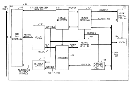
FIG. 1 shows a more detailed block diagram of the announcement circuit.
A brief description of each block follows.
Transcoder 101 accepts PCM/ADPCM samples and compresses (or
expands) the samples using Adaptive Differential Pulse Code Modulation
(ADPCM) to provide sixteen independent channels multiplexed onto serial
input/output lines. Transcoder 101 supports compression (or expansion) rates
of 64Kb/s (no compression, pass-through mode), 32Kb/s (2:1 compression mode)
7 ~ 8(39
and 16Kb/s (4:1 compression mode). Thc input PCM code words can be either A or MU-
I.AW format, as specified by the user. Transcoder 101 defaults to MU-LAW, unlessotherwise instructed.
S Circuit processor 103 provides the necessary per-channel controls, such as
compression rate and record/playback mode. Included in this circuit is a dual port RAM
(DPR). This array is accessed asynchronously by circuit processor 103 on one input and
read synchronously by transcoder 101 and by record control 112.
Circuit processor 103 also includes a microprocessor, such as an Intel- 8031,16K of
program ROM and 8K of RAM. The processor manages board operation by being the
control channel message interface to call processing, running maintenance tests and
overseeing the operation of memory processor 104.
In this particular implementation, memory 106, which stores the messages, contains
1 megabyte of dynamic RAM. The memory array, as will be seen, re~quires eighteen lines
for row/column addressing and two lines for bank selection. Access and refreshing of the
memory array is accomplished via memory control 105. An Intel- 8031 processor is used
in memory processor 104 for controlling the recording and playing of messages to and
from the memory. Only announcement messages are stored in the dynamic
announcement memory 106, and all control code structures and pointers used for control
purposes (e.g., link lists) are stored in static memory within circuit processor 103, memory
processor 104 or memory control 105.
The size of memory 106 bounds the total amount of message data ~and, thus,
announcement length) that can be stored. This space is flexibly dividable among any
number of different announcement messages whose lengths may vary. As discussed, the
storage space for each message is a function of the compression rates chosen for the
various recorded message announcements. For the embodiment shown, the maximum
message times are 2 minutes 8 seconds (all messages stored at 64Kb/s), 4 minutes 16
seconds (all messages stored at 32Kb/s) and 8 minutes 32 seconds (all messages stored at
16Kb/s). Of course, larger memories could be used to give other storage times.
* trade mark
~3~
- 8 -
As discussed, the announcement system allows ~lexible message lengths and the
announcements will be stored such that any single announcement can be of any length up
to the maximum memory space available. Individual announcements are re-recordable or
replaceable without any restriction on the length of the replacement message other than
that it must be able to fit in the unused space in memory 106.
FIG. 6 shows the structure of memory control 105 which solves the real time
constraint of retrieving one speech sample every 7.8$ mu $secs from rnemory 106. To
alleviate processing time burden on memory processor 104 when interacting with memory
106, recording or playback of a message is accomplished via block transfers between the
memory and playback interface 108, as shown in FIG. 7.
In the block transfer mode, memory processor 104's major task is to provide to
memory control 105 for each record or playback session the starting address of the block
to be transferred in or out of the memory. During each block transfer, sixteen speech
samples must be retrieved. However, since the speech samples may be compressed, the
number of bytes transferred during a single block transfer will vary depending on the
compression rate. For example, if the 8-bit message samples were compressed to 4-bit
samples, then only eight bytes would need to be transforrned to yield sixteen 4-bit samples.
This is controlled by memory processor 104 via memory control 105.
Since memory 106 is an 8-bit/byte word array, the recorded message samples are
stored in the memory one word (byte) at a time regardless of the compression rate.
However, as discussed above, each byte may have one, two or four data samples
depending upon the compression rate. Therefore, it is necessary, when reading data out
of the memory, to transform the 8-bit output words into the original sample sizes of 2-, 4-,
or 8-bits/speech sample. This conversion is performed by playback interface 108 (FIG. 7)
where byte ordering box 705 perforrns this task with the format shown in FIG. 10. Thus,
as shown for each block transfer, the number of bytes out of byte ordering box 705 is
always sixteen even though the number of input bytes varies.
Since the system expects sixteen channels of data per frame and the
message processor provides sixteen bytes of data per frame for each specific
channel, a buffering mechanism is used to collect the byte ordering box output
9 ~306~3(3~3
speech samples and multiplex them via multiplcxcr (MF) 701 (FIG. 7) to the input of
transcoder 101. This task is performed by buffer mcmory PSMA 704. This memory array
consists of a 512 x 8 dual port RAM. The PSMA is partitioned into two blocks, each
block 256 bytes dcep with each block containing sixlcen 16-byte buffers.
The PSMA interface is designed such that whcn one block is written the other
block is read simultaneously. This is possible sincc Lhe time required to write one block
equals the time to read the other block (i.e., 16 framcs = 2 msecs = 256 bytes). Upon
completion of processing a block (i.e., write or read), ~he block positions are interchanged.
The previously written block is now read and the prcviously read block is now written by
the byte ordering box with new speech samples. Thc operation of PSMA 704 is shown in
more detail in U.S. Patent No. 4,805,094 which issucd on February 14, 1989 to K.J. Oye,
et al. FIG. 8 shows the alternate arrangement of da~a in the PSMA buffer blocks.For recording messages, record interface 109, FIG. 9, works in the opposite
direction from playback interface 108 and demultiplcxes the ADPCM samples from
transcoder 101 serial output and transfers the demul~iplexed signals to memory 106.
Record interface lOg directs the channel output ADPCM out samples into dual-ported
two block buffer RSMA 903. Since memory 106 is an 8-bit wide memory array, RSMA
903 acts as a bu~fer to collect the samples and form full 8-bit words for all compression
rates.
Announcement circuit 40 (FIG. 1) allows only one recording session at the time
and, thus, the recording channel will be processed cvcry 2 msecs (i.e., every sixteen
frames) by message processor 104. During that 2 mscc period, the number of data bytes
stored in RSMA 903 varies, as discussed above, as a function of the compression rate.
From the message processor point of view, ~he block transfer protocol for
recording is the same as for playback and, thus, the only difference is that theprocessor is now writing to the memory instead of rcading from the memory.
Returning to FIG. 1, TDM bus interface 113 consists of four network
processing elements (NPE's) which provide sixteen access points to the TDM bus
for the sixteen channels The NPE's can be construc~ed in the manner set forth
in U.S. Patent 4,389,720, dated June 21, 1983. Circuit processor 103 can
31 3~
be constructed in the same manner as the microprocessor controller shown in
the aforesaid patent.
Playback control 111 multiplexes the sixteen channels from
transcoder 101 onto sixteen serial NPE channels. The NPE's then convert each
5 of their serial inputs into 8-bit parallel outputs.
The system can be expanded, as necessary, to hold more data by
changing the compression rate of already stored data. In this regard, the systemwould remove the announcement data from memory onto the system bus over
one channel. At the same time, the system records the removed announcement
10 data over another channel at a higher compression rate.
The first version of the announcement is then discarded and the original
storage space reused. Thus, the system can adapt, as needed, to the demand
for storage by compressing data only when there is a shortage of memory
capacity.
15 Conclusion
While our invention has been shown in conjunction with an
announcement system, it could be used by one skilled in the art for any number
of data storage systems. For example, the stored messages could be delivered to
a single user at a later time or to a limited number of users. Used in this
20 manner, the system would provide message store and forward services. Also,
the system could be used as an answering device with the storage of one or more
messages by a user.
Other types of arrangements are also possible, particularly where data
compression or data conversion is possible, in order to conserve storage space.
25 Such a system could be, for example, a video storage system where images,
perhaps pages of a video catalog, are stored in a compressed format and made
available over any number of channels to users.
Also note that data can come into the system in any form, analog or
digital, and can be converted by a front-end processor (either in the NPE or
30 otherwise) into a form suitable for compression and/or storage. While the
embodiment discusses one such message input line, the system is operable to
receive messages for storage over any number of lines simultaneously.