Language selection

Search

Patent 1306842 Summary

Third-party information liability

Some of the information on this Web page has been provided by external sources. The Government of Canada is not responsible for the accuracy, reliability or currency of the information supplied by external sources. Users wishing to rely upon this information should consult directly with the source of the information. Content provided by external sources is not subject to official languages, privacy and accessibility requirements.

Claims and Abstract availability

Any discrepancies in the text and image of the Claims and Abstract are due to differing posting times. Text of the Claims and Abstract are posted:

  • At the time the application is open to public inspection;
  • At the time of issue of the patent (grant).
(12) Patent: (11) CA 1306842
(21) Application Number: 561323
(54) English Title: CEILING RUNNER
(54) French Title: PROFILE DE PLAFOND SUSPENDU
Status: Deemed expired
Bibliographic Data
(52) Canadian Patent Classification (CPC):
  • 20/39
  • 20/18.6
(51) International Patent Classification (IPC):
  • E04C 3/00 (2006.01)
  • E04B 1/58 (2006.01)
  • E04B 2/76 (2006.01)
  • E04B 2/78 (2006.01)
  • E04B 9/00 (2006.01)
(72) Inventors :
  • BURKSTRAND, LOWELL E. (United States of America)
  • BURKSTRAND, GEORGE W. (United States of America)
(73) Owners :
  • BURKSTRAND, LOWELL E. (United States of America)
  • BURKSTRAND, GEORGE W. (United States of America)
(71) Applicants :
(74) Agent: RIDOUT & MAYBEE LLP
(74) Associate agent:
(45) Issued: 1992-09-01
(22) Filed Date: 1988-03-11
Availability of licence: N/A
(25) Language of filing: English

Patent Cooperation Treaty (PCT): No

(30) Application Priority Data:
Application No. Country/Territory Date
06/027,067 United States of America 1987-03-17

Abstracts

English Abstract


IMPROVED CEILING RUNNER

A B S T R A C T

A ceiling runner comprised of an elongated
generally U-shaped channel member having longitudinally
spaced openings in its web, each with one end portion
shaped and sized to confine a transversely arranged
upright C-stud therein. The remainder of the opening is
of such size and shape as to permit the c-stud to be
initially inserted therethrough with the web of its cross-
section extending longitudinally of the web of the channel
member and to be thereafter twisted about its longitudinal
axis to a relatively transverse position to snap into
place within said end portion, the web of the channel
member having a retaining tab at one side and a detent and
camming surface at the opposite side of the opening to
cause the C-stud to flex sufficiently to snap into said
end portion and to retain the C-stud within said end por-
tion once it has snapped into place. In addition, the
channel member has outwardly extending trim flanges at the
free ends of its legs which extend beyond the wall-board
only in a single plane parallel to the web and have no
depending structure, so as to provide an acoustical angle
appearance and a finished look along the line where the
upper edge of the wall meets the ceiling.


Claims

Note: Claims are shown in the official language in which they were submitted.


-18-
THE EMBODIMENTS OF THE INVENTION IN WHICH AN EXCLUSIVE
PROPERTY OR PRIVILEGE IS CLAIMED ARE DEFINED AS FOLLOWS:

1. A ceiling runner for securing in parallel upright
wall-supporting position a plurality of C-studs, each of
which has a pair of legs connected by a web, said runner
comprising:


(a) an elongated channel member which is generally
U-shaped in cross-section and has a pair of leg
elements with inner ends joined by a transverse
web element;


(b) said web element having a plurality of stud-
receiving openings formed therein and spaced
longitudinally thereof for the reception of
upstanding studs therethrough, each of said
openings having opposite end portions spaced
longitudinally of said member;


(c) said web element having opening-defining edge
portions defining said openings;


(d) each of said openings being generally rectangular
in shape and having longitudinal dimensions
greater than its transverse dimensions relative
to said channel member, said opening-defining
portions defining one end portion of each of
said openings so as to be constructed and
arranged to receive a C-stud therethrough in
pierced relation to said web element and to
confine the same therein in fixed position
relative thereto, the dimensions of said one end
portion being only slightly greater than that of
the C-stud to be received therein;


(e) each of said one end portions of each of said
openings having opposed transversely spaced ends;


-19-
(f) a stud-retaining tab carried by said opening-
defining portions and extending inwardly
adjacent one of said ends of said one end portion
of each of said openings in position to engage
such a stud and retain same in said one end por-
tion;

(g) a detent carried by opening-defining portions of
said web element opposite each of said tabs and
extending inwardly in position to cooperatively
engage and lock such a stud in confined position
in said one end portion of said opening;

(h) the distance between said each of said tabs and
its said opposed detent being less than the width
of the web of the C-stud to be received in said
opening; and

(i) each of said one end portions having a corner
opposite said detent, said edge portions of said
web element being constructed and arranged to
engage a trailing corner of a C-stud and to cam
the same inwardly when the stud is inserted into
said one end portion edgewise so as to have a
leading corner and a trailing corner with the
leading corner thereof extending into said oppo-
site corner of said one end portion, and the stud
is twisted about its longitudinal axis so as to
cause its trailing corner to move into said end
portion and the stud to snap into locked position
relative to said detent.

2. The structure defined in Claim 1 wherein said one end
portion has a corner opposite said detent, and a camming
surface carried by said opening-defining edge portions of
each of said openings adjacent to but outwardly of said

-20-

detent relative to said end portion, and constructed and
arranged to engage a trailing corner of a stud and to cam
the same inwardly when the stud is inserted into said end
portion edgewise so as to have a leading corner and a
trailing corner, with the leading corner thereof extending
into said opposite corner of said one end portion and the
stud is thereafter twisted about its longitudinal axis so
as to cause its trailing corner to move into said end por-
tion and the stud to snap into locked position relative to
said detent.

3. The structure defined in Claim 1, wherein said one end
portion is generally rectangular in shape and only
slightly larger in its dimensions relative to the C-stud
to be received therein.

4. The structure defined in Claim 1, wherein one of said
ends of said end portion is disposed opposite said detent
and the greatest distance between said detent and any por-
tion of said one end is less than the width of the web of
the C-stud to be received in said end portion.

5. The structure defined in Claim 1 wherein one of said
ends of said end portion is disposed opposite said detent
and said web element has transverse opening-defining por-
tions spaced longitudinally of said detent and defining a
corner with said oppositely disposed end and wherein the
distance between said corner and said detent is slightly
less than the width of the web of the C-stud to be
received within said opening.

6. The structure defined in Claim 1, wherein one of said
ends is disposed opposite said detent and said web element
has transverse opening-defining portions spaced longitudi-
nally of said detent and defining a corner with said
oppositely disposed end and wherein the distance between

-21-

said corner and said detent is substantially equal to the
width of the web of the C-stud to be received within said
opening.


7. The structure defined in Claim 1 wherein said detent
is spaced from said tab a distance less than the width of
the web of the C-stud to be received within said opening.


8. The structure defined in Claim 1 wherein said end por-
tion is generally rectangular in configuration and its
greatest dimension being transverse relative to said
channel member.


9. The structure defined in Claim 1 wherein said tab and
said detent each constitute a portion of said web element
and are disposed transversely opposite to each other rela-
tive to said channel member.


10. The structure defined in Claim 1 wherein said tab and
said detent are each disposed inwardly of said leg
elements.


11. The structure defined in Claim 1 wherein said tab and
said detent are each disposed inwardly of said ends of
said opening end portion.


12. The structure defined in Claim 1 wherein said end
portion of said opening is generally rectangular in shape
and extends transversely of said web with its longest
dimension being approximately 3-5/8 inches and its shorter
dimension being approximately 1-1/2 inches.


13. The structure defined in Claim 1 wherein said end
portion of said opening is generally rectangular in con-
figuration and its longest dimension extends transversely
of said web element and has dimensions approximating
2-1/2 inches in length and 1-1/2 inches in width.


-22-

14. The structure defined in Claim 2 wherein some of the
opening-defining portions of said web constitute said
camming surface.


15. The structure defined in Claim 1 wherein a portion of
said web element constitutes said detent.


16. The structure defined in Claim 1 wherein said leg
elements have upper ends with laterally outwardly
extending trim, said trim extending only parallel to said
web element and having a free outer edge devoid of
depending structure.


17. A ceiling runner for securing a plurality of C-studs
in parallel upright wall-supporting position comprising:


(a) an elongated channel member which is generally
U-shaped in cross-section and has a pair of
leg elements with inner ends joined by a trans-
verse web element;


(b) said web element having a plurality of stud-
receiving openings formed therein and spaced
longitudinally thereof for the reception of
upstanding studs therethrough, each of said
openings having longitudinally spaced end por-
tions;


(c) said web element having opening-defining surfaces
defining said openings;


(d) each of said openings having longitudinal
dimensions at least as great as its transverse
dimensions relative to said channel member and
having one end portion constructed and arranged
as to size and shape so as to receive therewithin


-23-
in close confining-and-shape-conforming relation
a conventional C-stud extending in substantially
fixed pierced relation to said web element;

(e) each of said one end portions of each of said
openings having transversely spaced ends;

(f) a stud-retaining tab carried by said channel
member adjacent one of said ends of said one
end portion of each of said openings and
extending inwardly into said opening in position
to engage such a stud and retain same in said one
end portion;

(g) a detent carried by said web element and extend-
ing inwardly opposite each of said tabs into each
of said openings in position to engage and coopera-
tively lock a C-stud in said one end portion of
said opening; and

(h) each of said one end portions having a corner
opposite said detent, said edge portions of said
web element being constructed and arranged to
engage a trailing corner of a C-stud and to cam
the same inwardly when the stud is inserted into
said one end portion edgewise so as to have a
leading corner and a trailing corner with the
leading corner thereof extending into said oppo-
site corner of said one end portion, and the stud
is thereafter twisted about its longitudinal axis
so as to cause its trailing corner to move into
said end portion and the stud to snap into locked
position relative to said detent.

18. The structure defined in Claim 17 and a camming sur-
face carried by said opening-defining surfaces of each of

-24-

said openings adjacent to but outwardly of said detent
relative to said one end portion, said camming surface
being constructed and arranged to engage a trailing corner
of a stud and to cam the same inwardly when the stud is
inserted into said end portion edgewise with a leading
corner thereof extending into an opposite corner of said
opening and the stud is thereafter twisted about its
longitudinal axis so as to cause the trailing corner to
move into said end portion and snap into locked position
relative to said detent.

19. The structure defined in Claim 17 wherein said open-
ings are equally spaced relative to each other along the
length of said channel member at eight (8") inch inter-
vals.

20. The structure defined in Claim 17 wherein said one
end portion includes a transversely extending edge of said
web element located opposite said tab and said detent and
defining a back wall for said one end portion along which
the web of the C-stud will extend when the C-stud is
snapped into locked position within said one end portion,
said transversely extending edge being generally slightly
convexly shaped in a direction away from said tab and said
detent.

21. The structure defined in Claim 17 wherein said one
end portion includes a transversely extending edge of said
web element located opposite said tab and said detent and
defining a back wall for said one end portion along which
the web of the C-stud will extend when the C-stud is
snapped into locked position within said one end portion,
said transversely extending edge being generally convexly
shaped in a direction away from said tab and said detent,
and wherein only the medial transverse portions of said
transverse edge are convexly shaped.

-25-

22. A ceiling runner for securing in parallel upright
wall-supporting position a plurality of C-studs, each of
which has a pair of legs connected by a web, said ceiling
runner comprising:

(a) an elongated channel member which is generally
U-shaped in cross-section and has a pair of leg
elements with inner ends joined by a transverse
web element;

(b) said web element having a plurality of stud-
receiving openings formed therein and spaced
longitudinally thereof for the reception of
upstanding studs therethrough, each of said
openings having opposite end portions spaced
longitudinally of said member;

(c) said web element having opening-defining edge
portions defining said openings;

(d) each of said openings being generally T-shaped
and having longitudinal dimensions greater than
its transverse dimensions relative to said
channel member, the top-bar of said T-shaped
opening extending transversely and the depending
leg of said T-shaped opening extending longitudi-
nally of said member;

(e) said opening-defining portions defining the top-
bar portion of each of said T-shaped openings so
as to be constructed and arranged to receive a C-
stud therethrough in pierced relation to said web
element and to confine the same therein in fixed
position relative thereto, said top-bar portion
of said openings conforming to the shape of such
a C-stud and the dimensions of said top-bar por-


-26-

tion of said openings being only slightly greater
than that of the C-stud to be received therein;

(f) each of said top-bar portions of each of said
openings having opposed transversely spaced ends;

(g) a stud-retaining tab carried by said opening-
defining portions and extending inwardly
adjacent one of said ends of said top-bar portion
of each of said openings in position to engage
such a stud and retain same in said top-bar por-
tion

(h) a detent carried by opening-defining portions of
said web element opposite each of said tabs and
extending inwardly in position to cooperatively
engage and lock such a stud in confined position
in said one end portion of said opening;

(i) the distance between each of said tabs and its
said opposed detent being less than the width of
the web of the C-stud to be received in said
opening; and

(j) each of said top-bar portions having a corner
opposite said detent, said edge portions of said
web element being constructed and arranged to
engage a trailing corner of a C-stud and to cam
the same inwardly when the stud is inserted into
said top-bar portion edgewise so as to have a
leading corner and a trailing corner with the
leading corner thereof extending into said oppo-
site corner of said top-bar portion, and the stud
is twisted about its longitudinal axis so as to
cause its trailing corner to move into said top-
bar portion and the stud to snap into locked
position relative to said detent.

-27-
23. The structure defined in Claim 22 wherein said top
bar of said T-shaped opening includes a transversely
extending edge of said web element located opposite said
tab and said detent and defining a back wall for said top
bar of said T-shaped opening along which the web of the C-
stud will extend when the C-stud is snapped into locked
position within said bar of said T-shaped opening, said
transversely extending edge being generally slightly con-
vexly shaped in a direction away from said tab and said
detent.

24. The structure defined in Claim 22 wherein said top
bar of said T-shaped opening includes a transversely
extending edge of said web element located opposite said
tab and said detent and defining a back wall for said bar
of said T-shaped opening along which the web of the C-stud
will extend when the C-stud is snapped into locked posi-
tion within said bar of said T-shaped opening, said trans-
versely extending edge being generally convexly shaped in
a direction away from said tab and said detent, and
wherein only the medial transverse portions of said trans-
verse edge are convexly shaped.

25. A ceiling runner for securing a plurality of C-studs
in parallel up-right wall-supporting position for sup-
porting walls, ceilings and fire-walls thereabove,
comprising:

(a) an elongated channel member which is generally
U-shaped in cross-section and has a pair of leg
elements with inner ends joined by a transverse
web element.

(b) said web element having a plurality of stud-
receiving openings formed therein and spaced
equally longitudinally thereof;

-28-
(c) said web element having opening-defining surfaces
defining said openings;

(d) each of said openings having longitudinal dimen-
sions at least as great as its transverse dimen-
sions relative to said channel member and having
one end portion of generally rectangular shape
extending transversely of said web element;

(e) a plurality of upstanding C-studs, one each of
which is locked within one of said rectangular
end portions in relatively close-fitting
surrounded relation;

(f) said C-studs having portions thereof extending
upwardly through said openings of said channel
member a substantial distance thereabove, each of
said C-studs having a pair of opposed legs and a
web extending therebetween;

(g) a plurality of stud-retaining tabs, one each of
which is carried by said web element adjacent
each of said C-studs and retains the same within
said rectangular opening;

(h) a plurality of detents, one each of which is
carried by said web element and extends inwardly
opposite one of said tabs in cooperative stud-
locking relation with said tab;

(i) the distance between each of said detents and its
said opposed tab being less than the transverse
dimensions of the web of one of said studs;

(j) a plurality of camming surfaces, one each of
which is carried by said opening-defining sur-
faces adjacent one of said detents and extends

-29-
away therefrom in a direction away from said
stud and

(k) a fire-wall secured to said portions of said
studs extending above said channel member and
extending upwardly from said channel member.

- 30 -

26. An improved ceiling runner extending around the
periphery of the room for holding wallboards where the
runner incudes a ceiling portion and a depending portion,
the improvement comprising:

(a) an elongated U-shaped cross sectional member
having two leg elements interconnected by a
web portion at the lower end of each leg
element, said leg elements having edge
portions extending away from each other at
the upper end of each leg element; and

(b) cut out portions spatially disposed from
each other along the web of said U-shaped
cross sectional member.

27. The invention as set forth in claim 26 wherein
said edge portion is extended outwardly an amount generally
equal to the width of a trim margin.

28. The invention as set forth in claim 26 wherein
said upstanding leg elements generally are of shorter
dimension than the separation provided by said web portion.

29. The invention as set forth in claim 26 wherein
said cut out portions are spaced on eight inch centers.

30. The invention as set forth in claim 26 including:

(a) a plurality of studs extending through said
cut out portions forming a stud wall.

-31-

31. The invention as set forth in claim 28 including:
e) a plurality of wallboard panels flatly
disposed against both sides of said studs
and extending upwardly into flush
engagement with said edge portions; and
f) a plurality of ceiling panels overlying
said edge portions to create a trim
margin around the periphery of the room.

32. The invention as set forth in claim 28 including:
e) fastening means securing said plurality
of studs to said leg elements at their
upper ends.

33. The invention as set forth in claim 31 including:
g) fastening means securing said plurality
of wallboard panels to said studs.

34. A method of providing a finishing margin around the
interior periphery of a room where the walls and ceiling meet
comprising the steps of:
a) establishing a stud wall secured at its
bottom and permitting the upper ends to
float freely;
b) capturing the upper ends of said studs in
a ceiling runner having an edge portion
on each side extending outwardly when
finished an amount equal to the width of
a trim border;
c) securing wallboard panels to said stud
wall and extending the upper edge of said
panels into communication with said edge
portions; and
d) disposing ceiling panels above said edge
portions to form a margin with said edge
portions.

-32-

35. An improved ceiling runner comprising:
a) an elongated channel member having a pair
of leg elements interconnected by a
transverse web element extending at right
angles thereto;
b) said channel member being constructed and
arranged to capture a plurality of spaced
upright studs therewithin;
c) each of said leg elements having free end
portions supporting a marginal edge along
its length;
d) each of said free end portions extending
outwardly from the remainder of its
supporting leg element in a single plane
throughout and at right angles thereto;
e) each of said free end portions having
transverse dimensions greater than the
thickness of wallboard so as to extend
outwardly therebeyond and thereby provide
an exposed trim edge when a sheet of
wallboard is abutted against said leg
element and its said free end portion.


36. An improved ceiling runner comprising:
a) an elongated channel member having a pair
of leg elements interconnected by a
transverse web element extending at
right angles thereto;
b) each of said leg elements having free end
portions supporting a marginal edge along
its length;
c) each of said free end portions extending
outwardly from the remainder of its
supporting leg element in a single plane
throughout and at right angles thereto;
d) each of said free end portions having
transverse dimensions greater than the


-33-
thickness of wallboard so as to extend
outwardly therebeyond and thereby provide
an exposed trim edge when a sheet of
wallboard is abutted against said leg
element and its said free end portion;
and
e) said web element having a plurality of
stud-receiving openings formed therein
and spaced longitudinally thereof for the
reception of upstanding studs there-
through.

37. The structure defined in claim 36 wherein each of said
free end portions have transverse dimensions approximating
one and one-half inches.

38. A ceiling runner to be extended around the periphery of
a room for holding wallboard of predetermined thickness,
comprising:
a) an elongated channel member having a web
element and a pair of upstanding leg
elements extending upwardly from opposite
sides of said web element:
b) said web element having areas thereof cut
out at locations spaced along its length
and being constructed and arranged to
receive upstanding studs therethrough;
and
c) marginal trim means carried by each of
said leg elements and constructed and
arranged to extend outwardly therefrom
throughout its extent in a single plane
parallel to said web element and having a
free edge terminating in said plane, and
being of sufficient width to extend
outwardly beyond the outer surface of
such wallboard when the latter is abutted

-34-

against one of said leg elements and its
associated trim means, to thereby provide
a revealed marginal edge.


39. A ceiling runner to be extended around the periphery of
a room for holding wallboard of predetermined thickness,
comprising:
a) an elongated channel member having a web
element and a pair of upstanding leg
elements, one each of which extends
upwardly from opposite sides of said web
element at right angles thereto;
b) said web element having areas thereof cut
out at locations spaced along its length
and being constructed and arranged to
receive upstanding studs therethrough;
c) a pair of terminal flanges, one each of
which is supported by one of said leg
elements and is extended outwardly
therefrom throughout its width in a plane
normal thereto; and
d) each of said flanges terminating in a
free edge disposed outwardly from its
supporting leg element a distance
substantially greater than the thickness
of such a piece of wallboard to thereby
provide a revealed marginal edge when
such a piece of wallboard is abutted
against said flange and its supporting
leg element.


40. A ceiling runner to be extended around the periphery of
a room for holding wallboard of predetermined thickness,
comprising:
a) an elongated channel member having a web
element and a pair of upstanding leg
elements, one each of which extends


-35-

upwardly from opposite sides of said web
element at right angles thereto;
b) said web element having areas thereof cut
out at locations spaced along its length
and being constructed and arranged to
receive upstanding studs therethrough;
and
c) each of said leg elements having a
terminal flange extending outwardly, only
in a plane parallel to said web element
and having a free edge disposed in said
plane a distance substantially in excess
of 5/8" from its supporting leg element,
whereby a revealed marginal edge will be
provided when a panel of wallboard is
abutted against said flange and its
supporting leg element.

41. A ceiling runner to be extended around the periphery of
a room for holding wallboard of predetermined thickness,
comprising:
a) an elongated channel member having a
transverse web element and a pair of
upstanding leg elements, one each of
which extends upwardly from opposite
sides of said web element at right angles
thereto and each of which has a terminal
flange with a free edge;
b) said web element having areas thereof cut
out at locations spaced along its length
and being constructed and arranged to
receive upstanding studs therethrough;
c) a panel of wallboard extending along one
of said leg elements and having an upper
end abutting against the terminal flange
supported thereby; and


-36-
d) said channel member being constructed and
arranged so that said terminal flange of
said leg element along which said panel
is arranged extends outwardly therebeyond
with its free edge substantially in the
plane of said upper end of said panel, to
thereby provide a revealed marginal edge
thereat.

Description

Note: Descriptions are shown in the official language in which they were submitted.


I. DESCRIPTION

Description of the Prior Art

The prior art involves the extensive and costly
expenditure of much time and labour in order to construct
new interior walls, including fire-walls, sound-walls and
ceiling. Time, in addition to cost, is frequently of the
essence in industrial building construction and hence any
effective cuts which can be made in the amount of time
required to erect such walls and ceilings is doubly desir-
able and rewarding.

Present construction procedures and materials
utilize metal C-studs secured together at their tops at
ceiling level by an inverted channel member into which
their upper ends extend and to the legs of which the
wallboard, which becomes the interior wall, is secured at
opposite sides of the channels. To accomplish this, the
channel members at the floor and ceiling must be marked off
to properly locate the relative positions of each end of
each stud relative to the channel member and thereafter the
leg of each stud is secured to the corresponding leg of the
channel member through the use of self-tapping screws which
extend through the respective leg members. Errors in
measuring and marking frequently occur. These procedures
require substantial amounts of wasted time and labour. In
addition, if perchance one of the studs, prior to their
securement to the channel member, is bumped accidentally by
another workman, or one is permitted to fall sidewise, a
~omino effeat results ~ith all of the studs .....

l3a6~
-2- :

falling and a new entire free-stand re-arrangement being
required, again involving a waste of time and effort. As
a consequence, anything that can eliminate or reduce the
amount of time and labor required to provide such an
assembly is sorely needed.

In the event any fire-wall or sound-wall is
required above the ceiling, present procedures call for
measuring the distance each stud is to extend above the
ceiling to the overhead deck and then cutting a separate
stud to that length. Because of the presence overhead of
structural beams, heating and cooling ducts, plumbing,
sprinkler pipes, electrical pipes and equipment, etc.,
these lengths vary and thus much time and labor is con-
sumed in determining the length and location of these
relatively short additional studs. Moreover, each stud
must be secured somehow at each end, while working under
relatively cramped conditions, and the fire-wall or sound-
wall must, thereafter, be secured thereto. Because of
these problems, the installation of the ceiling grid is
sometimes withheld until the room walls and the sound-
walls, or fire-walls thereabove have been constructed,
which means that the ceiling grid must thereafter be
constructed one room at a time, another time-wasting
requirement. Also, when the studs are cut to length for
the separate fire-wall or sound-wall, the presence of
obstacles above the ceiling, such as heat and cooling
ducts makes it very difficult to frame straight sound-
walls or fire-walls.

Another time and labor consuming problem still
besetting the construction industry is that of uneven
floors. Such floors cause the length of the studs between
the floor and the ceiling to vary. This means that
under prior procedures, the length of each stud must be

l;~G~8 ~;~

--3--

separately measured in advance of cutting it in prepara-
tion for placing it in position within the ceiling runner
for fastening thereto.

Using present methods, walls are built up only to
the ceiling and the trim-molding, commonly called a
J-bead or L-bead is applied at the juncture of the wall
and ceiling to provide a more finished appearance. The
installation of such trim-molding requires a substantial
amount of labor and materials. Anything that can be done
to reduce or eliminate such procedures will provide a
substantial saving.

As indicated above, it is considered desirable to
provide a finished appearance at the juncture of the walls
and ceiling and toward that end, acoustical angle molding
is conventionally applied. Such molding is typically
plastic or metal and is comprised of elongated strips
which are L-shaped or angulated in cross-section, much
like a piece of angle-iron. Such moldings, however, make
is difficult, if not impossible, to provide the "revealed
edge" at the juncture of the side wall and ceiling, which
is considered desirable for uniformity since each of the
ceiling panels located more toward the center of the room
frequently have such a revealed edge. The n revealed edge n
is the edge of the panel which becomes exposed when a
strip of the material from which the panel is made is
relieved or cut away from the under surface of the panel
along, adjacent to, and parallel to the edge of the panel.
This is normally provided by a procedure called scribing
or rabbeting in which such material is cut away along a
straight edge. Since the ends of ceiling panels are con-
ventionally abutted against the side walls of the room,
scribing is an awkward, inconvenient, difficult and time-
consuming procedure at best. Anything which can be done
to obviate this procedure will be welcomed by the
industry.

--4--

An additional time-consuming and labor-wasting
procedure which is currently required is the formation of
special openings in the channel members to which the C-
studs are secured in order to permit the extension of
electrical, telephone and other types of wire therethrough.
Currently, such openings are cut as needed and, of course,
result in additional cost for labor and the consumption of
additional time, which in turn increases the total amount
of time required to complete the project.

In order to appreciate the benefits of our new
system for framing inner walls, it is important to
understand the procedures and materials used in current
conventional building practices. only in this way can the
full advantages be recognized. Such practices include the
initial laying out of markings on the floor showing wall
locations in accordance with the floor plan. This
includes plumbing up and markings on the ceiling grid and
on the deck, if a fire-wall or sound-wall is to be built
above the ceiling. These initial markings are required in
all wall building procedures. Thereafter, starting with
an outer wall, a drywall ceiling runner in the form of an
inverted C-channel is secured around the perimeter wall.
This is also utilized in our system. At this point, if a
sound-wall or fire-wall is to be included above the ceil-
ing, it is necessary to also build a lower runner for thesound-wall or fire-wall, which consists of an upwardly
facing channel member secured to the ceiling gridwork
directly above the ceiling runner. It is also necessary
to build an upper runner (an inverted channel) for the
sound-wall or fire-wall immediately below the deck in
order to be able to secure the studs for these walls.
Because of the presence of numerous obstacles already
installed immediately below the deck, such as heating and
cooling ducts, electrical wiring, plumbing, etc., the
construction of the upper and lower runners for such addi-


--5--

tional studs above the ceiling gridwork requires a sub-
stantial expenditure of time, labor and materials. With
our system, the need for these expenditures is obviated
because the fire-walls and sound-walls are automatically
framed with the framing of the lower walls, with no addi-
tional requirements.

The next conventional step is to secure the floor
runners, which are upwardly facing C-channels, along the
perimeter walls. Such floor runners are also needed in
our system. Thereafter, the spacing of the studs is
determined. This involves laying out such spacing by
applying markings to the channels of both of the upper and
lower runners for both the lower wall and the upper sound-
walls or fire-walls. This requires considerable time and
effort and is obviated by our system.

The next step is to measure the distances be-
tween the lower runner and the ceiling runner in order to
determine the length of the studs. Such studs are of un-
even length because uneven or non-level floors create dif-
ferences in such lengths of up to two inches. The studsare then cut according to such measured lengths. This
measuring and cutting is obviated by our system.

The cut studs are then stood in place free-stand
within the ceiling and floor runners according to the
markings, preparatory to securing all of them thereto,
first to the ceiling runner at their upper ends and then
to the floor runner at their lower ends. Self-tapping
screws may be used for this purpose. It is just prior to
such secural that a domino effect may cause all of the
studs to fall, if one is accidentally tipped sideways by a
workman. When this occurs, all of the studs must be
repositioned. All of these efforts, including the secur-
ing of the studs with self-tapping screws is eliminated
by our system.


When each of the perimeter walls have been framed
in the above manner, steps are taken to assemble the inner
walls which extend therebetween. Toward that end, one end
of an inverted C-channel member is conventionally secured
to one of the perimeter ceiling runners by cutting away
port~ons of the end so as to leave the web extending over
the peripheral ceiling runner to be secured thereto. The
inverted C-channel is secured along its length to either
the deck or the ceiling grid (if present), after plumbing
from the floor markings. Such inverted C-channels are so
secured as ceiling runners wherever an inner wall is to be
constructed, the end of individual sections being per-
mitted to overlap or otherwise secured together.

When this has been accomplished, the correspond-
ing floor runner consisting of an upwardly facing C-
channel is secured to the floor directly below each such
ceiling runner. Mark-ings for each stud are then made
upon the runners, measurements are made for each stud and
then each stud is cut accordingly, if needed. Again, the
studs are arranged free-standing within the floor and
ceiling runners preparatory to securing same with self-
tapping screws, first at their tops to the ceiling runner
and thereafter at their lower ends to the floor runner,
again with danger of a domino effect in the event one of
the studs falls over prior to being secured. Most of the
above markings, measurements, securing and cutting opera-
tions are obviated by our system.

In conventional wall building, if a sound-wall or
a fire-wall is to be built above the ceiling, all of the
securing of the runners, the marking, the measurements,
the cutting of C-studs to desired length, and the
fastening of the studs to the runners must be repeated.
All of these operations are obviated by our system because
such fire-walls and sound-walls are automatically framed


when we frame the lower interior wall. In our system, the
studs extend through the one ceiling runner to the deck
and are held in fixed position thereby so that there is no
need the measurements for the additional studs, or for the
additional securing operations.

We are aware of a number of patents, as described
herein, which reflect the prior art. United States Patent
No. 2,078,491 issued to Graham, shows a U-shaped channel
member in Fig. 7 without openings in the web. Fig. 6
thereof shows a skeletonized web having openings 5 to
accommodate electrical wiring, etc.

U.S. Patent No. 2,079,635 issued to Sharp, shows
an H-shaped connector member with a hollow centrai cavity
which is used within the hold of a ship to form enclos-
ures.

U.S. Patent No. 2,371,921 issued to Tucker, showsan elongated angle iron with openings equal in size to
hold studs which extend parallel to the length of the
angle iron and hence would have only one side to support a
wall. It is designed to prevent lateral shifting of cargo
within a ship.

U.S. Patent No. 2,699,669 issued to Nelsson,
shows an elongated stud 16 having a transverse web con-
necting a pair of legs 18, 20 with laterally extending
flanges 42, 43. The web has no openings.

U.S. Patent No. 2,909,251 issued to Nelsson,
shows an elongated channel member having a web 12 with
legs 15 extending at an acute angle thereto so as to con-
verge. Each leg has a laterally extending flange from
which a downwardly converging strip 18 depends. The web
has no openings except narrow transverse slots 50 to allow

--8--

the insertion of studs 44. The runner is one and one-half
times the width of the stud and the openings are narrow
slots.

U.S. Patent No. 3,027,605 issued to Nelsson,
shows a ceiling runner 60 with flanges 66 and web 36a and
depending strips 68 which converge. The web has no
openings.
U.S. Patent No. 3,349,529 issued to Byssing,
shows a U-shaped channel member without any openings and
having flanges with depending edge moldings. It i9 used
for making a hollow wall partition system. The flanges do
not extend in the same plane throughout their length.

U.S. Patent No. 3,465,488 issued to Miller, shows
a U-shaped member having an imperforate web and converging
legs.

U.S. Patent No. 4,018,020 issued to Sauer, shows
an imperforate elongated metal channel with no provision
for the extension of C-studs therethrough.

U.S. Patent No. 4,461,135 issued to Anderson
et al, shows prior art in Fig. 1 in which a channel member
has an imperforate web 15 and depending legs.

Brief Summarv of the Invention

The problems outlined hereinabove are either
eliminated or substantially reduced by our invention, as
is evidenced by the enthusiastic endorsement which it has
received from large architechural firms and building
contractors for the substantial reduction in labor costs
which it effects and for the improved aesthetic effects
accomplished as a result of its use. These substantial

- 9 -

benefits are attained as a direct result of the plurality
of equally spaced uniquely shaped openings of the U-shaped
ceiling runner which are each shaped to receive an upright
C-stud in pierced relation, while the latter is oriented
so that its web extends parallel to the length of the web
of the ceiling runner. The opening-defining portions of
the web of the ceiling runner are shaped so as to cam the
legs of the C-stud inwardly and to flex its web when the
stud is twisted about its longitudinal axis, whereby the
C-stud can snap into transversely extending position past
a detent which cooperates with an opposite tab to lock the
C-stud in relatively fixed position within one end portion
of the opening. The end portion of the openings into
which the C-studs are thus snapped is shaped and sized to
conform to the cross-sectional shape of the stud, so that
the stud is confined and surrounded by the web and held
therein. Thus, a wall can be framed in a matter of a few
minutes simply by inserting a plurality of C-studs into a
plurality of such openings in a pair of our ceiling run-
ners and merely twisting them about their longitudinalaxis, thereby locking each of them in place. Since the C-
studs extend through our ceiling runner, there is no need
to cut the studs even though the floor to ceiling height
may be less than the stud length. Since such a ceiling
runner can be used at the floor as well as at the ceiling,
the lower as well as the upper end portions of the C-stud
can be so secured simultaneously.

Since our invention provides for the extension of
the C-stud through the ceiling runner, it permits the
simultaneous framing of the room wall and the sound-wall
or fire-wall, as desired, with substantially less labor.
Thus, the C-studs can be inserted within the uniquely-
shaped openings to whatever elevation adjacent the upper
deck that the obstructions thereat will permit, and the
stud can be cut to that length. When the stud has been so

13G~ 12

--10--

cut, it can be snapped into position within the ceiling
runner and the lower wall and the fire-wall or sound-wall
is thereby completely framed. Thus, a great deal of labor
is saved. Moreover, the fire-wall or sound-wall above the
ceiling will be straight, and the portion of the stud
above the ceiling will already be firmly secured at its
lower end within the ceiling runner.

Since the entire wall, including the fire-wall or
sound-wall above the ceiling level, is automatically
framed simultaneously and quickly by merely snapping the
C-studs into position into the uniquely-shaped openings as
described above, we have eliminated a great deal of labor
because we have eliminated the separate framing of the
sound-wall or fire-wall. We have also eliminated the
marking or scoring at the ceiling and at the floor for the
stud locations. We have also eliminated the need for
securing each stud at both levels with self-tapping
screws, welding or stud crimpers. Thus, a substantial
saving in time is effected and a substantial amount of
labor is eliminated.
Heretofore, it has often been impractical to
install ceiling grids throughout an entire floor of a new
construction, particularly where a substantial number of
sound-walls or fire-walls above the ceiling are required.
In such instances, ceiling grids are frequently installed
room by room, because the grid work interferes substan-
tially with the work required to frame and install the
separate fire-walls or sound-walls above the ceiling,
thereby making it prohibitively costly. With the use of
our new ceiling runner and the automatic framing of the
fire-wall or sound-wall which it provides, it is now prac-
tical to install the ceilinq grids throughout the entire
floor at one time. This effects a substantial saving in
labor because it is much more cost efficient to install
the ceiling grid over an entire area at one time rather
than accomplishing the same room by room.


In addition to the above, our ceiling runner has
laterally extending edge portions which extend only in a
plane parallel to its web and have no depending structurè.
This configuration provides a finished acoustical angle
appearance at the side wall-ceiling juncture which is con-
sidered highly desirable in the building trade. It also
greatly facilitates the production of the revealed edge of
the ceiling panels along the walls, which is also con-
sidered highly desirable since it gives a ceiling having
panels with revealed edges a uniform appearance throughout
the room. The edge portions of our new ceiling runner
greatly facilitates the scribing or rabbeting operation
which is required to provide a desired revealed edge at
the ceiling-wall juncture.

The need for ceiling trim in order to provide a
neat finished appearance at the wall-ceiling juncture has
been eliminated by our ceiling runner since its edge por-
tions (which extend only parallel to the web and beyond
the~waIl-board and have no depénding structure) automati-
cal-ly provides a finished edgë-molding appearance, thereby
obviating the need for the application of trim-moldings
such as the conventional J-bead or L-bead. The separate
installation of such conventional beads requires the
expenditure of much time and labor and has now been elimi-
nated by our invention.

Brief Description of the Drawings

A detailed description of one preferred embodi-
ment of the Improved Ceiling Runner is hereafter described
with specific reference being made to the drawings, in
which:

Fig. 1 is a partial perspective view of one of our
Improved Ceiling Runners with a plurality of C-studs

13(~
-12-

extending therethrough and an interior and sound-wall panel
secured thereto;

Fig. 2 is a vertical sectional view taken along
line 2-2 of Fig. l;

Fig. 3 is a plan view of one of our Improved
Ceiling Runners with an intermediate portion thereof broken
away;

Fig. 4 is a plan view of a portion of one of our
Improved Ceiling Runners with a C-stud shown in section as
it is initially introduced edgewise into one of the openings
thereof;

Fig. 5 is a plan view of the same portion of one of
our Improved Ceiling Runners with the same C-stud as that in
Fig. 4, shown in section in a second and flexed position as
it is being twisted about its longitudinal axis and cammed
into one end portion of the opening;

Fig. 6 is a plan view of the same portion of one of
our Improved Ceiling Runners with the same C-stud as that in
Figs. 4 and 5, shown in section in final locked-in position
within said one end portion of the opening to complete its
installation as part of the framing of the wall; and

Fig. 7 is a plan view of a portlon of another form
of an Improved Ceiling Runner having a generally T-shaped
opening and with a C-stud shown in section in a position
corresponding to that of the stud shown in Fig. 4.

Detailed Description of the Invention

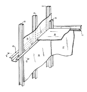
Fig. 1 shows a pair of our metal ceiling runners
10 and 11 connected at a corner of a room pierced by a

13~ 2


plurality of C-studs 12, 13, 14 and lS which, in turn sup-
port a pair of interior wall panels 16, 17, a ceiling
panel 18, and a panel 19 of a sound-wall. This figure
illustrates the manner in which our ceiling runners are
utilized and appear once the C-studs have been received
therein and the framing of the wall has been completed.

Fig. 2 shows a cross-sectional view of one of our
ceiling runners. As shown, it consists of an elongated U-
shaped channel member 20 which is characterized by a
pair of leg elements 21, 22 which are joined by a trans-
verse web element 23 that forms the bottom of the channel.

~ The free-ends of the legs 21, 22 carry outwardly
extending edge portions 24, 25 identified as trim flanges.
These flanges 24, 25 extend throughout the length of the
channel member 20 and beyond the panels of wall-board lÇ
and 26, as shown. They are approximately 1-1/2 inches in
width. The standard thickness of wallboard panels such
as 16 and 26 is 5/8 inch. The flanges 24, 25 each extend
parallel to the web 23 throughout their entire length and,
as shown, have no depending structure connected to their
outer and free edges.~

As best shown in Fig. 3, our ceiling runner is
provided with a plurality of generally rectangular
openings, the longer ~dimensions of which extend longitud-
inally of the channel member 20 and web 23. As describedhereinafter, the longitudinal dimension of these openings
is at least as great as the transverse dimension of the
end portion thereof which eventually receives the C-stud
12 therein in locked-in relation. Preferably, the longi-
tudinal dimension is slightly greater than such transversedimension in order to facilitate initial insertion of the
C-studs into these openings. These openings are spaced at
eight (8 n ) centers throughout the length of the runner.

-14-

As shown, the openings 27 are generally rectangu-
lar in shape, and have opposite end portions 28 and 29.
The most important characteristic thereof is that one of
said opening end portions, the end portion 28, i5 shaped
and sized so as to receive and confine a C-stud 12 therein
in relatively fixed position. This is accomplished, as
shown, by shaping the end portion 28 so as to conform to
the exterior shape of a conventional C-stud 12 and to size
it so that it is only slightly larger, and to hold the
stud therein with a retaining tab 30 and a detent 31.

As shown, the web 23 has opening-defining por-
tions identified generally by the numeral 32 and the
retaining tab 30 and detent 31 are part of such opening-
defining portions. In addition, the edge portions just
outwardly of the detent 31 and extending away from the end
portion 28, constitute a camming surface 33. The end por-
tion 28 has opposite ends 34 and 35. A transverse edge 36
constitutes a back wall against which the C-stud 12 abuts,
and forms a corner 37 with the end 35 which is located
opposite the detent 31.

Reference to Figs. 4-6 will reveal how our ceil-
ing runner enables a worker to frame an inner wall and
a sound-wall or fire-wall simultaneously, quickly and
easily. After the ceiling runner has been mounted so as
to extend along beneath the ceiling grid, as hereinbefore
described, a plurality of C-studs, such as C-stud 12 are
inserted through the openings 27 and snapped into place.
Fig. 4 shows how the C-stud is oriented initially. It
will be seen it will be inserted edgewise with its longest
dimension extending longitudinally of the opening to faci-
litate entrance. Once it has been inserted to its fullest
extent, it is twisted about its longitudinal axis, as
shown by the arrows so that its leading corner 40 will
engage the rear or back wall 36 and its trailing corner 41

1306~ ~Z
-15-

will engage the camming surface 33. The latter urges the
leading corner 40 into the corner 37 of the opening so
that the leg 42 of the C-stud bears against the end 35.
As can be seen by reference to Fig. 5, the leg 42 flexes
substantially relative to the web 43 which also flexes
slightly. The opposite leg 44 also flexes as it slides
past the detent 31, as shown.

Once the corner 41 of the stud passes the detent
31, ~he entire stud snaps into locked position, as shown
in Fig. 6. It will be seen that the retaining tab 30 and
detent 32 positively lock the C-stud in place in closely-
confined relation. No further connection to the ceiling
runner is required. This procedure is repeated for each
stud and requires only a few seconds each, so that an
entire wall can be framed in a manner of a few minutes.
It will be seen that the studs, which extend up to the
deck above for the fire-wall or sound-wall to be construc-
ted above the ceiling, are automatically thereby framed
since the upper end portions of the C-stud are held in
fixed and true upright position by the ceiling runner.
All that remains to complete the walls is to affix the
wall board to the legs of the studs, above and below the
ceiling runner, in any manner desired.

It will be seen that the distance between the tab
30 and detent 31 is less than the transverse dimensions of
both the opening end portion 28 and the C-stud 12. Also,
the distance between the detent 31 and all portions of the
end 35 is less than such transverse dimensions.

Fig. 7 shows a portion of a ceiling runner having
the same cross-sectional shape as shown in Figs. 1-6 with
a modified form of opening 50. As shown, it is generally
T-shaped and has one end portion Sl which corresponds to
the cross-bar portion of the letter T, and a second end

1306~ 1Z
-16-

portion 52 which corresponds to the depending leg of the
T. It includes a tab ~3, a detent 54, and a camming sur-
face 55, as well as a rear wall 56. The C-stud is snapped
into locked position in the same manner as hereinbefore
described. The opening is longer in its longitudinal
dimension than its transverse dimension and the end por-
tion 51 is shaped and sized generally to conform to the
exterior of the C-stud. The primary difference over that
shown in Figs. 1-6 is the convex shape of the rear wall
56.

It will be seen that the intermediate portions of
the rear wall 56 are slightl~ convex. The leading corner
40 of the C-stud engages this surface and the latter adds
a more longitudinal thrust to the leg 42 as the C-stud is
twisted about its longitudinal axis, thereby facilitating
installation of the C-studs. Once the C-stud has snapped
into full transverse locked position, it is held thereat
by the restraining tab 53 and detent 54.

/ Reference to Fig. 2 reveals the substantial
improvement provided by our ceiling runner with respect to
aesthetic effects. It will be seen that the tr_m flanges
24 and 25 extend laterally outwardly beyond the conven-
-tional wallboard 16 and 26 so as to provide a neat and
finished effect which obviates the need for the applica-
tion of strips of J-bead or L-bead edge-moldings. Also,
the outer edges of these flanges greatly facilitates the
scribing operation which provides the "revealed edge" of
the ceiling panel along the wall-ceiling juncture. Thus,
a substantial amount of material and labor is saved.

From the above, it can be seen that through the
use of our improved ceiling runner, substantial time and
labor savings can be accomplished in that the markings,
the securing operations, the separate construction of the

-17-

fire-wall or sound-wall and the need for separate edge-
molding have been eliminated. In addition, the fire-walls
or sound-walls will be straight and substantial quantities
of material will be ~aved. Moreover, the end product
will have a much more pleasing aesthetic effect.

In considering this invention, it should be
remembered that the present disclosure is illustrative
only and the scope of the invention should be determined
by the appended claims.

Representative Drawing
A single figure which represents the drawing illustrating the invention.
Administrative Status

For a clearer understanding of the status of the application/patent presented on this page, the site Disclaimer , as well as the definitions for Patent , Administrative Status , Maintenance Fee  and Payment History  should be consulted.

Administrative Status

Title Date
Forecasted Issue Date 1992-09-01
(22) Filed 1988-03-11
(45) Issued 1992-09-01
Deemed Expired 1997-09-02

Abandonment History

There is no abandonment history.

Payment History

Fee Type Anniversary Year Due Date Amount Paid Paid Date
Application Fee $0.00 1988-03-11
Maintenance Fee - Patent - Old Act 2 1994-09-01 $100.00 1994-08-31
Maintenance Fee - Patent - Old Act 3 1995-09-01 $100.00 1995-08-30
Owners on Record

Note: Records showing the ownership history in alphabetical order.

Current Owners on Record
BURKSTRAND, LOWELL E.
BURKSTRAND, GEORGE W.
Past Owners on Record
None
Past Owners that do not appear in the "Owners on Record" listing will appear in other documentation within the application.
Documents

To view selected files, please enter reCAPTCHA code :


To view images, click a link in the Document Description column. To download the documents, select one or more checkboxes in the first column and then click the "Download Selected in PDF format (Zip Archive)" or the "Download Selected as Single PDF" button.

List of published and non-published patent-specific documents on the CPD .

If you have any difficulty accessing content, you can call the Client Service Centre at 1-866-997-1936 or send them an e-mail at CIPO Client Service Centre.


Document
Description 
Date
(yyyy-mm-dd) 
Number of pages   Size of Image (KB) 
Drawings 1993-11-04 2 56
Claims 1993-11-04 19 606
Abstract 1993-11-04 1 31
Cover Page 1993-11-04 1 11
Description 1993-11-04 17 678
Representative Drawing 2002-02-05 1 10
Fees 1995-08-30 1 34
Fees 1994-08-31 1 35