Note: Descriptions are shown in the official language in which they were submitted.
--2--
The invention relates to a framework for a fishfarming
enclosure of the type comprising at least two longitudinal
frame members and at least two transverse frame members
extending between the longitudinal members, the frame
members being interconnected by a pivot joint means to
permit relative angular movement between the frame
members, in use.
Various frameworks of this type are known. In one known
arrangement of this type the frame members are connected
to each other by a pivot joint means comprising pivot
bearings extending laterally at the ends of the frame
members and a pivot bolt extending between the pivot
bearings. Such arrangements however suffer from the
disadvantages that they are not easily assembled, are
generally difficult to manipulate and are not robust, in
use.
This invention is directed towards providing an improved
framework for a fishfarming enclosure which will overcome
at least some of tnese difficulties.
According to the invention there is provided a fishfarming
enclosure framework of the type comprising at least two
longitudinal frame members and at least two transverse frame
members extending between the longitudinal frame members, the
frame members being interconnected by a pivot ~oint means to
permit relative angular movement between adjacent frame
members, in use, about a generally horizontal pivot axis, the
~ ,s
1306~1
-- 3 --
pivot ~oint means comprising a male spi~ot part on one frame
member for engagement with a female socket part on another
frame member and a pivot bolt extending between the spigot and
socket parts, the pivot bolt having a non-metallic bushing
provided over the bolt.
Preferably the spigot part comprises a pivot bolt
receiving bushing mounted on one frame member and the
socket part comprises a pair of side wings extending from
another frame member to embrace at least a portion of the
qpigot part, the side wings each having a bolt receiving
hole for alignment with the spigot bushing.
In a preferred embodiment of the invention the pivot bolt
receiving bushing is mounted by a reinforcing strap to the
frame member.
Preferably locking means are provided to secure the pivot
bolt in position. Typically the locking means comprises a
cotter pin extending transversely through the shank of the
bolt.
Preferably the head of the cotter pin is provided with an
enlarged portion for manipulating the bolt in use, and to
prevent the pin being pulled through the shank of the
bolt.
In one embodiment of the invention each frame member
comprises at least a pair of spaced-apart frame elements
having connecting elements extending therebetween. The
13~ 91
elements ar~ usually arranged to support a walkway which
may be of expanded metal mesh or the like.
In one embodiment of the invention the framework is of
substantially rectangular configuration having a plurality
of substantially rectangular sub-frameworks.
In one case the framework comprises a pair of spaced-apart
outer longitudinal members, a central longitudinal member
extending parallel to and spaced apart between the outer
longitudinal members, and a plurality of transverse
members extending between the longitudinal members.
The invention will be more clearly understood from the
following description thereof ~iven by way of example only
with reference to the accompanying drawings in which:
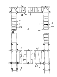
Fig. 1 is a plan view of a framework according to
the invention forming part of a fishfarming
enclosure, also according to the invention,
Fig. 2 is a perspective view of portion of the
framework of Fig. 1,
Fig. 3 is a perspective view of another portion of
the framework of Fig. 1,
Figs. 4a and 4b are respectively elevational and
13~
plan views of a female socket part of a joint V in
Fig. 3,
,
Figs. 5a and 5b are respectively elevational and
plan views of a male spigot part of the joint V,
Figs. 6a and 6b are respectively side elevational
and perspective views of a pivot bolt forming part
of the joint,
Fig. 7 is a cross sectional view on an enlarged
scale of the joint V,
Figs. 8a and 8b are respectively plan and
elevational views of a joint VIII in Fig. ~,
Fig. 9a is a plan view of a joint IX in Fig. 2,
Fig. 9b is a cross sectional view on the line A-A
in Fig. 9a,
Fig. 9c is a cross sectional view on the line B-B
in Fig.ga, and
Fig. 10 is a plan view of a joint X in Fig. 3.
Referring to the drawings and initially to Fig. 1 there is
illustrated portion of a fishfarming enclosure according
1;~(J ~it~9~
to the invention including a framework also according to
the invention, a portion 1 of which is illustrated in
Fig. 1. The upper right-hand corner portion of the
framework 1 of Fig. 1 is illustrated on an enlarged scale
in Fig. 2 and the lower right-hand corner portion of the
framework 1 of Fig. 1 is illustrated on an enlarged scale
in Fig. 3. Various joints used for connecting parts of the
framework 1 together are illustrated in Figs. 4 to 9.
The fishfarming enclosure is in this case of substantially
rectangular shape and includes six substantially
rectangular sub-frames 5, each of which defines a cage in
which fish are reared. It will be appreciated that any
suitable number or arrangement of sub-frameworks may be
employed.
The framework 1 is formed from a number of interconnected
longitudinal and transverse frame members, namely a pair of
spaced-apart outer longitudinal frame members, only one 7 of
which is illustrated and a central longitudinal frame member
8 extending parallel to and equi-spaced apart from the outer
longitudinal frame members. Outer transverse members 9, and
inner transverse members 12 extend between the longitudinal
frame members to define the sub-frameworkæ 5. Walkways which
may, for example, be of expanded metal sheet material, are
provided on each of the frame members as are protective rails.
13()~
In more detail, each of the frame members 6 to 12
comprises at least a pair of frame elements indicated by
the appropriate reference letters a and b and connecting
elements 17 extending between the frame elements. In this
case the frame elements and connecting elements are all of
box-section material however it will be appreciated that
they may be of any suitable construction.
The frame elements of adjacent frame members are inter-
connected by a pivot joint means which permits relative
angular movement between the frame members in use to take
account of movement of the waterway in which the enclosure
is sited. Each of the joint means comprises a spigot
part, a female socket part and a pivot bolt extending
between the parts. The differences between the various
constructions of joint illustrated in Figs. 4 to 9 is in
the mounting and reinforcement of the various joints means
in accordance with its particular position in the
framework 2.
Referring to Figs. 4 to 7 there is illustrated one
construction of ioint which corresponds to a straight
joint between adjacent longitudinal or transverse frame
members. The joint means comprises a male spigot part 25
illustrated in Figs. 5a and 5b, a female socket part 26
illustrated in Figs. 4a and 4b, and a pivot bolt
illustrated in Figs. 6a and 6b. A non metallic bushing 29
is provided over the bolt 27 to eliminate noise, and to
~3~ i'r3.1
--8--
facilitate easy motion and replacement for wear. The
spigot part 25 includes a bushing 30 which is attached at
one end of the frame element 1OA by a metal strap 31 which
extends over the bushing 30 and is welded to the underside
and top of the frame elemen~ 1OA as illustrated in Figs.
5a and 5b.
The female socket part 26 comprises a pair of side wings
35 which are welded on opposite sides of the respective
frame member and extend outwardly to define a socket 28
for reception of the male spigot part 25. A bushing 36 is
provided on each wing 35 and the bushings 36 are aligned
in use with the bushing 30 of the male spigot part 25 for
reception of the pivot bolt 27 which is retained in
position by a cotter pin 42 extending through a hole 41 in
the shank of the bolt 27. The pin 42 has an enlarged head
portion 43 to prevent the pin 42 passing through the shank
of the bolt and to assist manipulation of the bolt, in
use.
Referring to Figs. 8a and 8b there is illustrated a female
socket part 50 of another joint used in the framework 1.
In this case the joint SO is attached to a respective
longitudinal or transverse member by reinforcing struts 51
arranged in a generally triangular configuration.
Referring to Figs. 9a, 9b and 9c there is illustrated
another female socket part 55 which is of similar
13(~'31
construction to the socket part of Figs. 8a and 8b except
that in this case the socket part is provided at one
corner of a longitudinal frame element and reinforcing
struts 56 are arranged in a substantially right-triangular
configuration.
Referring to Fig. 10 there is illustrated another male
spigot part 60 which is similar to that described above
with reference to Figs. 5a and 5b. In this case the joint
is reinforced by diagonal reinforcing plat~s 61 extending
between adjacent transverse and longitudinal members 1Oa,
8a.
We have found that frameworks formed using the type of
joint means described above are particularly robust in use
while facilitating relative movement between adjacent
longitudinal and transverse frame members to take account
of variations in the flow of water in the waterway in
which the fishfarming enclosure is mounted. The framework
can also be readily assembled quickly and simply by
inserting the male spigot parts into female socket parts,
inserting the pivot bolt between the parts, manipulating
the bolt into position and retaining it by a locking means
such as a cotter pin.