Note: Descriptions are shown in the official language in which they were submitted.
~3~7~
FIELD OF THE INVENTION
This invention relates to a wheeled carriage for
transporting a person such as a child and more particularly to
such a carriage having structure to retract the wheels con-
currently to readily convert the carriage into a car seat.
BACKGROUND OF THE INVENTION
Nonconvertible car seats designed to support an in-
fant or toddler are presently available. If a parent is taking
the child along on a shopping trip, for example, the child is
placed in the conventional child's car seat until the car arrives
at the shopping center. Typically a separate stroller is opened
up, and the child is physically transferred from the car seat to
the stroller~ Generally such strollers are collapsible, and
must be manipulated to be converted into their full operating
size and configuration. The removal of a sometimes
- 3 -
~1 3~
uncooperative child from a car seat, in order to place the
child in the stroller, is somewhat annoying, particularly if
the child starts "acting up". Upon the return trip, the
stroller has to be collapsed, to conveniently store it in the
car, and the child, who may be sleeping, must be transferred
back to the car seat.
one convertible stroller, described in U.S. Patent No.
2,720,911 by Lantz, does not permit the child to remain in
the stroller during conversion to a car seat. The wheels
must be retracted independently, and each front wheel has its
own locking mechanism which must be separately disengaged by
hand. The stroller must be tipped onto its side or elevated
well above the ground before the wheels can be positioned
inside of the superstructure of the carriage. Further, the
back rest element collapses during conversion and does not
support the child in the car seat configuration.
SUMMARY OF INVENTION
It is therefore an object of this invention to provide
an improved convertible carriage having wheels or other
roller devices which are conveniently and concurrently
retractable to convert the carriage into a car seat.
It is a further object of this invention to provide such
a carriage which in one configuration is a car seat which is
XX-ys5J 4
',
; X~
,
readily removable from the car without unstrapping the child from
the seat, is easily converted into a stroller and, after-use as a
stroller, is convertible back to a car seat, again without
disturbing the child.
It is a further object of this invention to provide such
a carriage which can lock the wheels in an extended position
utilizing a single locking mechanism.
It is a further object of this invention to provide such
a carriage which can have a wheel base larger than the
superstructure of the carriage yet can retract the wheels into the
shorter superstructure in the car seat configuration.
Therefore this invention seeks to provide a convertible
carriage comprising:
a superstructure including seat means for carrying a
person to be transported;
a plurality of wheel means;
wheel support means, movably interconnected with said
superstructure, for rollably supporting said wheel means to
transport said superstructure when said wheel support means and
said wheel means are in an extended position below said
superstructure;
said wheel support means including a plurality of leg
members, one for separately supporting each said wheel means,
arranged in a front set and a back set each of said leg members
- having separate pivotal interconnections with said superstructure;
means, operatively connected to said wheel support
means, for relocating said wheel means concurrently between said
,
,
', ,', ,' '~
~7a)~6
extended position and a retracted position in said superstructure
by driving said front set in the fore and upward direction during
retraction and said back set in the aft and upward direction, said
means for relocating including:
first drive means for moving one of said front and back
sets between said extended and said retracted positions, said
first drive means including a drive member to which force is
directly applied by an operator of the carriage; and
second drive means for interconnecting the remaining set
and first drive means to drive that other set between said
extended and said retracted positions;
means for locking said leg members in said extended
positions to extend outwardly and downwardly from said pivotal
interconnections.
This invention results from the realization that a truly
effective stroller convertible into a car seat can be achieved by
a carriage having wheels which extend concurrently to rollably
transport the carriage and conveniently retract concurrently into
a non-collapsing superstructure.
This invention features a convertible carriage. There
is a superstructure including seat means for carrying a person to
be transported, and a plurality of wheel means. The carriage
further includes wheel support means, movably interconnected with
the superstructure, for rollably supporting the wheel means to
transport the superstructure when the wheel support means and said
wheel means are in an extended position. Also included are
Sa
, ~
7~6
means, operatively connected to the wheel housing means, for
relocating the wheel means concurrently between the extended
position and a retracted position in the superstructure.
In one embodiment, the wheel support means is a single,
integral structure coupling together the wheel means~ The
structure may be a base member retractable into the
superstructure. In another embodiment, the wheel support
means includes a plurality of leg members, one for separately
supporting each of the wheel means. The means for relocating
may include first drive means for driving at least one leg
member and corresponding wheel means between the extended and
retracted position, and a second drive means for
interconnecting the remaining leg members and the first drive
means to drive the remaining leg members and corresponding
wheel means between the extended and the retracted position.
The first and second drive means respectively include first
and second pulley means, each pulley means being operatively
connected to at least one leg member, and the second drive
mean~ further includes cable means interconnecting the ~irst
and second pulley means to drive them and their corresponding
leg members concurrently. The carriage may further include a
locking mechanism for releasably locking the first drive means
to secure the leg members in the extended position. The
locking mechanism has as single element to which force is
applied by an operator of the carriage to disengage the
XX-VS5J 6
,
, . ,
... .
~3 ~
first drive means and the locking mechanism from each other.
Further, the first drive means may include actuating means,
connected to at least one of the leg members, to which force
is applied by the operator for moving the leg member between
the extended and the retracted position. The actuating means
may be a cross member connected between two of the leg
members.
In another embodiment, the superstructure includes means
for receiving the wheel means in the retracted position, such
as a cavity formed on each said of the superstructure by
opposing walls, and the means for relocating moves the wheel
means to rest and over the pans in the retracted position.
The means for relocating may arcuately move each of the wheel
means in a substantially vertical plane such that all the
wheel means move in fore and aft directions relative to the
superstructure. The seat means may include a rigid backrest
member which may be adjustably pivotable relative to the
remainder of the superstructure. The seat means remains
usable during relocation of the wheel means between the
extended and the retracted positions.
DESCRIPTION OF PREFERRED EMBODIMENTS
Other objects, features and advantages will occur from
the following description of preferred embodiment and the
accompanying drawings, in which:
XX-VS5J 7
X
Fig. 1 is a axonometric, partial cutaway view of a
convertible carriage according to this invention with its
wheels in the extended po~ition;
Fig. 2 is an enlarged view of the locking device shown
in Fig. 1;
Fig. 3 is a partial end view of the carriage of Fig. l;
Fig. 4 is a partial end view, similar to that of Fig. 3,
showing the carriage with the wheels in the retracted
position and with the wheel covers now disposed beneath the
wheels;
Fig. 5 is a side elevational view of an alternative
carriage according to this invention showing the extended and
retracted positions of the wheels:
Fig. 6 is a partial-cutaway, axonometric view of the
carriage of Fig. 5 with the canopy removed and the handle
moved forward;
Fig. 7 is an exploded axonometric view of the windlass
drums and cables of Fig. 6;
Fig. 8 is an enlarged view of a portion of the locking
mechanism shown in Fig. 7;
Fig. 9 is a side elevational view of the shock-absorbing
device within one of the drums of Fig. 7; and
Fig. 10 is an enlarged view of the wheel recesses shown
in Fig. 6.
XX-VS5J 8
X
. . . ~ , j,
~3~7~
This invention may be accomplished by a carriage which
has a number of wheels which are moved concurrently between
an extended position in which the carriage serves as a
stroller and a retracted position in which the carriage
serves as a car seat. The wheels may be supported by a
single structure which retracts into superstructure of the
carriage. Alternatively, each wheel is carried by a separate
leg member. The leg members are interconnected by a pulley
and cable system or other linkage so that movement of one or
more leg members drives the remaining leg members to relocate
the wheels concurrently between the extended and retracted
positions.
A carriage according to this invention having a single,
integral structure for supporting its wheels is shown in Fig.
1. Superstructure 1 has an adjustable chair back member 2
which may be adjusted by a conventional rack type positioner,
generally illustrated at location 3. A child supporting
urface 4 iB alBo illustrated. The superstructure 1 is
configured to function in the manner of a car seat for
transporting the child upon an automobile trip. Base member
6 i8 also shown, having a pair of upwardly extending members
7 and 7' interleaved between wall members 8, 10, 8' and 10'
of the superstructure. The transporter illustrated in Fig.
1 is in the extended, stroller mode, whereby the
superstructure 1 is separated from base member 6 as shown.
The transporter is in the stroller mode, since the
XX-VS5J g
7~
parent may readily push the transporter to convey the child
along the ground. An extended U-frame pushing bar 57 may be
placed in position 1' for pushing the transporter with the
child facing in the direction of motion, or it may be placed
in position 2' for pushing the transporter with the child
facing the one pushing the stroller. ~uring this second
scenario the seat back 2 may be reclined to a horizontal
position, thus converting the stroller to a pram.
The locking mechanism shown in Fig. 1 is depicted
enlarged in Fig. 2. The locking mechanism includes lock bar
16 pivotably coupled to the sidewall portion of the base
member 6 by pivot pin 17. Locking bar 16 is upwardly spring
biased by spring 18 against pin stop 19 which is also affixed
to the side wall portion of base member 6. A single follower
roller 21 is illustrated in Fig. 2, and all four track
follower rollers are illustrated in Fig. 1, which ride upon
track 22 affixed to base member 6. All follower rollers are
rotatably coupled to superstructure 1 and aid in the easy
relative motion of the superstructure with respect to the
base.
Locking bar 16, coupled to base member 6, maintains
superstructure 1 extended from base member 6 since track
follower roller 21 supports the weight of superstructure 1
against locking bar 16. Thus gravity tends to urge roller 21
downwardly, to urge locking bar 16 clockwise against stop pin
XX-VS5J 10
~3~7~
19. When it is desirable to cause the transporter to be
retractably telescoped to form a compact body which may be
placed in the automobile, the parent manipulates the locking
device by two distinct motions. The parent lifts the
superstructure 1 to enable downward motion of release rod 5,
which permits counterclockwise rotation of locking bar portion
20 about pivot 17 to enable the roller followers 21 and 21'
to clear the right-hand locking bar portion 20. A foot
actuated bar 26 is directly coupled to lock release rod 5 to
facilitate the application of a second force to the lock,
after the user applies a first force against the
superstructure in the upward direction to cause the track
follower roller 21 to clear the locking bar 16.
Superstructure 1 is thus permitted to descend toward the
bottom portions of base member 6, to collapse the device.
Thus, a convenient and yet safe mechanism is provided for
collapsing the transporter, so that the child is never in
danger of being injured by a sudden inadvertant release of
the lock, to cause the superstructure to plummet downwardly.
A large opening 33 at the rear portion of the base member
is also illustrated, opening into a storage area 35 for
convenient storage of various items. Two wheels 34 and 36 are
rotatably mounted to lower portions of base member 6. Two others
are similarly mounted to the opposite side portion of the base
member, wheel 34' being partially indicated. A seat belt,
XX-VS5J 1l
X
~ 1 ~C17~
not shown, is also positioned upon the superstructure.
Adjustment in the angle of the seatback 2 is effected by
pulling up upon seatback release rod 41, to cause the lower
portions thereof to clear the locking teeth of the release
rod device 3; release rod guide members 44 and 46 are also
indicated in Fig. 1. A conventional return spring, not
shown, is also provided. The seat back may be reclined to a
horizontal position for use as a pram.
One of the wheel cover members 13 of Fig. 1 is
illustrated in greater detail in Figs. 3 and 4. Wheel cover
13 is pivotably mounted along its extended length by means of
a longitudinal pivot pin 48. A torsional spring 50 urges the
wheel cover 13 in a clockwise direction so that the lower
portion 51 of wheel cover 13 illustrated in Fig. 3 is urged
against the side of the base member 6. Upon unlocking of the
locking device, the superstructure moves downwardly toward
the collapsed position, and the lower edge portion 51 of the
wheel cover member continues to be urged against side
portions of wheel 34, until it is able to be fully rotated in
a clockwise direction by the above-mentioned torsion spring,
to cause it to cover the rim of the wheel, as illustrated in
Fig. 4. Thus when the now-collapsed transport is
repositioned back into the car, the lower wheel portions are
shielded from the car seat, and any debris which may have
gathered about the wheels are captured,
XX-VS5J 12
~ 30~
and do not soil the seat of the car. Also, owing to the
configuration of the wheel covers, the transport is made
more stable when positioned upon the car seat, compared to
having the wheels alone press against upper portions of the
car seat. When the transport is again removed from the car,
and base member 6 extended from superstructure 1, the
resulting reaction force of wheel 34 against the lower
portions of the wheel cover at location 56 causes the wheel
cover to rotate in a counterclockwise direction to clear the
wheel, and again be spring-biased against the side portions
of base member 6 as illustrated in Fig. 3. Wheel covers 13
may be described as folding wheel covers, since their
rotation about the hinge pin 48 causes them to be
automatically folded under the wheels as described.
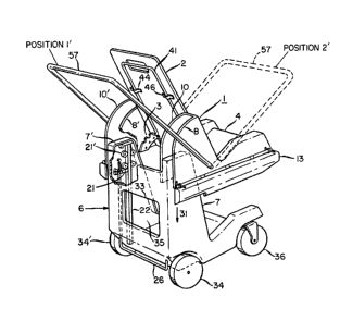
An alternative convertible carriage 60 according to this
invention is shown in Fig. 5. Carriage 60 includes
superstructure 62 having canopy 64 and handle 66, shown in
the stroller position. Leg members 68, 70 rotatably support
wheels 72, 74, respectively, and are shown in the extended
position. When carriage 60 is to be converted into a car
seat, leg members 68, 70 and their corresponding wheels are
concurrently relocated inside of superstructure 62 as shown
in phantom.
This construction achieves a wheel base, that is, the
front-to-back distance between wheels 74, 72, which is larger
XX-VS5J 13
X
S
than the length of superstructure 62 when the wheels are in
the extended position. The large wheel base provides
increased stability when carriage 60 is used as a stroller,
yet the wheels are retractable into superstructure 62 to
provide a car seat which fits the typical gap of seventeen or
eighteen inches between the rear seat and the aft portion of
the front seat of many cars.
Carriage 60 is shown in greater detail in Fiq. 6 with
relocation system 76, shown in phantom, interconnecting leg
members 68, 70, and relocation system 78 interconnecting leg
members 80, 82. As described below, release bar 84 is
actuated by the operator of carriage 60 to disengage leg
member 68, 82 from the extended position which in turn
releases leg members 70, 80. Torsion spring 86 resists
forward rotation of release bar 84 and biases it in the
direction indicated by arrow 87. Handle 66 is shown in the
pram po~ition locked onto stop 90 by latch 91 rather than on
stop 88 as shown in Fig. 5. Backrest 92 is pivotably
ad~usted by pulling release bar 94 against biasing springs
96, 98 to disengage an end of rod 94 from teeth 100.
Carriage 60 can be arrested in position by sliding tabs
102, 104 within cross member 106 to engage wheels 72, 108.
Cross member 106 is partially cut away to reveal rod 110
passing through the spokes of wheel 108.
XX-VS5J 14
X
~!1 3~
In the retracted position, leg members 68, 70 rest within
cavity 112 formed by parallel walls 114, 116. Similarly, leg
members 80, 82 rest within cavity 118. Cross member 106 is
received by recesses shown in walls 114, 120.
Relocation system 78 is shown in greater detail in Fig.
7 having pulleys 122, 124 serving as windlass drums for
cables 126 and 128. Cable 128, for example, is connected at
end 130 to pulley 124 and at end 132 to pulley 122. Cables
126, 128 lie within grooves passing around pulleys 122, 124.
When the leg members and wheels of carriage are in the
extended position, one end of release bar 84 rests within
hole 134 of pulley 124. Release bar 84 locks pulley 124 in
this position, and cables 126, 128 restrain front pulley 122 to
lock leg member 80 and its corresponding wheel in the
extended position. Rotation of bar 84 in the direction of
arrow 136, such as by placing the heel of a foot on cross
member 106 and pressing with the toe against bend 138, frees
pulley 124 to rotate such that bar 84, fixed in position
relative to the superstructure, allows pulley 124 to rotate
past it such that the end of bar 84 travels through groove
140 while the weight of superstructure 62 draws it toward the
ground. The rotation of pulley 124 drives pulley 122 in the
opposite direction through cables 126, 128. Leg members 68,
70, 80, 82 are thereby driven concurrently in the fore and
aft directions, each moving
XX-VS5J 15
.~
X
arcuately in a vertical plane. Once superstructure 62 is
resting on the ground, the operator lifts cross member 106 to
place it within the recesses in walls 114, 120, Fig. 6. Leq
members 70, 80 and their corresponding wheels are thereby
also drawn within cavities 112, 118.
The locking relationship of bar 84 and pulley 124 is
shown in Fig. 8. Tab 142 is biased toward an orientation
normal to groove 140 by torsion springs 86, Fig. 6.
Rotation of bar 84, however, aligns tab 142 with groove 140
to allow rotation of pulley 124. The other end of bar 84
simiIarly engages the pulley associated with leg member 68.
Leg member 82, Fig. 7, and pulley 124 are rotatably
secured to the superstructure by bolt 150. Post 152 slidably
engages pulley 124 as shown in Fig. 9. Pulley 124 includes
groove 154 which receives post 152. Compression spring 156
allows movement of pulley 124 and leg member 82 relative to
each other to ~unction as a shock absorber.
The lower portion of superstructure 62 is shown in
greater detail in Fig. 10. Guides 160, 162 support a pin
passing through them and interlocking portions of backrest
92. Platform 164 serves as the seat. Pan 166 catches mud,
dirt, or water which may drop from the wheels in the
retracted position within cavity 112. Cavity 168 between
walls 114, 120 serves as a storage area.
XX-VS5J 16
: %
~3~
Lightweight, rigid materials are preferred for
super~ructur~ 62 ~nd the l~g ~e~r~ to facilitate lifting of
the carri~ge ~n~ pl~c~ment on the ~eat of a car. This invention
i8 not li~ted to a cable and pulley 8y8tem, but this drive
arrangement is desired ~ince it i8 light in weight.
Alternatively, arrangements such ~s intermeshing plastic gears
or other linkage can be utilized.
Although ~pecific features of the invention are sbown in
some drawings and not others, this is for convenience only as
each feature Gay be combined with any or all of the other
features in accor&nce with the invention.
Other e0b~diments will occur to those skilled in the art
and are within the following claims:
XX-VS5J -17-