Note: Descriptions are shown in the official language in which they were submitted.
~L307~L0S
The present invention relates generally to app~ratus for
coating a web material, such as paper or board web, and more
particularly, to apparatus for coating a web including a
coating nip formed between a rotating counter roll and a
smoothing or coating member or between a pair of smoothing
members, through which nip the web to be coated is passed
with a coating substance being applied to the web prior to
passing through the nip.
Prior art relevant to the present invention includes CA
Patents 563,750, 689,123, and 1,184,75~, FI Patent
Application 83 3464, and SE Patents 8205805 and 8205807.
Reference is also made to a paper published in Paper 201
(1984) wherein a 'Short-Dwell Coater" (a trademark of Beloit
Corporation) is described.
Various arrangements are known for coating one or both
sides of webs, such as paper webs. For example, roll coating
devices, blade coating devices and blade-rod coating devices
are known for single sided and two-sided coating of paper
webs.
In conventional roll coating devices, the web passes
through one or more coating nips formed by two opposed rolls
with one or more pools of size or coating substance being
formed in connection with the nip or nips. In blade coating
devices, a counter roll and a coating blade or,
alternatively, a pair of blade devices, form the coating nip.
In a blade-rod coating device, a counter roll and a blade rod
form the coating nip in connection with which the coating
substance is applied to the web.
The running speeds of web coating devices have increased
in recent years. Speeds as high as 1500 to 1800 m/min are
,
13~)7~S
reached during the web coating operation. Moreover, as the
widths of paper webs have increased, the precision and
durability requirements imposed on the coating devices, i.e.,
on the coating blades or blade-rods of the coating devices,
have become even more exacting.
In this connection, a problem has arisen in the
operation of conventional coating arrangements in that
coating blades become worn quite rapidly, e.g., requiring
replacement after operating for only about 8 to 24 hours. On
the other hand, blade coating devices are advantageous in
that the transverse distribution of the guantity of coating
substance applied to the web can be adjusted quite precisely
since the blade is sufficiently flexible in the direction
transverse to the direction of movement of the web, that is,
in the width dimension of the web.
On the other hand, the rods in blade-rod coating devices
are worn less rapidly than blades, requiring replacement only
after one to two weeks of operation which is considered
satisfactory. However, a drawback of coating arrangements
using coating rods is that it is generally not possible to
adjust the distribution of the coating substance on the web
with the precision desired since the coating rod mounted in
its support is so rigid that it will not yield to a
sufficient extent in order, for example, to accommodate
variations in thickness of the web to be coated.
~L30~LO~;
In one aspect, the invention provides an apparatus or
coating a web of material, such as paper or board web, moving
through said appara~us comprising, a frame; an elongate
smoothing member mounted on said frame having a longitudinal
dimension extending transversely to the direction o~ movement
of the web through said apparatus, said smoothing member
being flexible in its longitudinal direction; a counter
member situated in opposed relationship to said smoothing
member and forming a smoothing nip therebetween through which
the web is adapted to pass; means for applying a coating
substance onto the web prior to the web passing through said
nip; and means for applying a linear load in said smoothing
nip, said nip loading means including means for applying a
load to said smoothing member along its longitudinal
dimension; the improvement comprising: said elongate
smoothing member includes an outer part having a
substantially convex-shaped cross-section in a plane
perpendicular to its longitudinal dimension, said outer part
of said smoothing member forming said smoothing nip with said
counter member, said elongate smoothing member further
including an arm portion projecting from said convex-shaped
outer part, and wherein said arm portion is connected to said
frame to thereby connect said elongate smoothing member to
said frame; said outer part of said smoothing member forming
said smoothing nip is substankial].y shaped as a segment of a
circle and said smoothing member further includes reinforcing
means cooperating with said circular segment outer part for
reinforcing said outer part, said reinforcing means defining
substantially planar bearing surface means; and said means
for applying a load to said smoothing member comprise at
~3~
least one internally pressurizable loading hose means
engaging said planar bearing surface means defined by said
reinforcing means or engaging an inner surface of said arm
portion.
In preferred embodiments of this aspect, the invention
provides:
The above combination wherein said counter membsr
comprises a second elongate flexible smoothing member
including an outer part having a substantially convex-shaped
cross-section in a plane perpendicular to i~s longitudinal
dimension, said outer parts of said smoothing members forming
said smoothing nip between them.
The above combination wherein said arm portion
projecting from said convex-shaped outer part is
substantially plate shaped.
The above combination further including means
cooperating with said smoothing member loading means for
selectively variably ad~usting the load applied to said
smoothing member along its longitudinal dimension.
The immediately above combination wherein said at least
one internally pressurizable loading hose means have a first
surface region engaging said smoothing membex, and wherein
said means for selectively variably adjusting the load
applied to said smoothing me~ber comprise means for applying
a load to a second surface region of said loading hose means
- 3a -
~;~
1;~07~L0~i
opposite from said first surface region thereo~ engaging said
smoothing member, whereby variations in the load applied to
said loading hose means results in a corresponding variation
in the area of said first surface region of said hose means
engaging said smoothing member, which results in a
corresponding variation in the load applied to said smoothing
member by said hose means, the internal pressure of said hose
means remaining substantially constant; and wherein said
means for selectively variably adjusting the load applied to
said smoothing member include a series of counterpieces
engaging said hose means; wherein said loading hose means
have a substantially non~extensible circumference whereby the
circumference of said loading hose means remains
substantially constant regardless of variations in the
loading pressure; wherein said means ~or selectively variably
adjusting the load applied to said smoothing member ~urther
include a series of separately adjustable threaded members
cooperating with respective counterpieaes.
- 3b -
~30~
A more complete appreciation of the present invention
and many of the attendant advantages thereof will be readily
understood by reference to the following detailed description
when considered in connection with the accompanying drawings
in which:
FIG. 1 is a front elevation view in section
schematically illustrating a first embodiment of rod coating
apparatus in accordance with the invention;
FIG. 2 is a front elevation view in section
schematically illustrating a second embodiment of rod coating
apparatus in accordance with the invention, the coating nip
being formed between two coating rods situated in opposed
relationship with respect with each other;
FIG. 3 is a front elevation view in section
schematically illustrating a modification of the first
embodiment of the rod coating apparatus illustrated in FIG.
l;
FIG. 4 is an axonometric view, partially broken away, of
the rod coating apparatus illustrated in FIG. 3;
FIG. 5 is a front elevation view schematically
illustrating supporting and loading arrangements of a coating
or smoothing member;
FIG. 6 is a front elevation view in section
schematically illustrating an embodiment of rod coating
apparatus which operates in accordance with the principles of
operation of the embodiments illustrated in FI&S 1 and 3;
~3~73L~
FIG. 7 is a front elevation view in section
schematically illustrating an embodiment of rod coating
apparatus in accordance with the invention and which is
provided with an arrangement for washing the coating rod;
FIG. 8 is a front elevation view in section
schematically illustrating an embodiment of blade coating
apparatus in accordance with the invention;
FIG. 9 is a front elevation view in section
schematically illustrating an embodiment of coating apparatus
utilizing a smoothing or coating member of shaped cross-
section having a convexly curved face situated in opposed
relationship to a counter roll;
FIGS. lOA - lOE illustrate various configurations of
smoothing members used in coating apparatus of the type shown
in Figs. 9, 11 and 12, Fig. lOA comprising a section view
taken along line A-A of Fig. lOC;
FIG. 11 is a front elevation view in section
schematically illustrating a second embodiment of coating
apparatus utilizing a smoothing member having shaped cross-
section; and
FIG. 12 is a front elevation view in sectionschematically illustrating an embodiment of coating apparatus
in accordance with the invention utilizing a pair of opposed
smoothing members having shaped cross-sections.
~eferring now to the drawings wherein like reference
characters designate identical or corresponding parts
throughout the several views, and more particularly to the
~3~710~
embodiments of the rod coating apparatus illustrated in Figs.
1 and 3, the web coating apparatus comprises a rotating
counter roll 10 having a smooth cylindrical surface 10' over
which the web to be coated, e.g. paper web W, is passed. A
coating or smoothing rod 20, which may be either solid
cylindrical or tubular, forms a coating nip N with the
surface 10' of counter roll 10 through which the web to be
coated runs.
~0
-5a-
~ 3 ~ 71 ~ ~
In accordance with the invention, the rod 20 is supported by
a special arrangemen~ provided in frame 30 of the apparatus. The
coating rod 20 comprises an elongate member having a longitudinal
dimension extending transversely to the direction of movement of
web W and in accordance with th~ invention iæ substantially as
flexible and pliable as conventional coating blades so that the
distribution of the coating substance in the transverse or width
dimension of the web can be adjusted su~iciently precisely and
steeply that a layer of coating substance will have a substantially
uniform thickness regardless of variations in the thickness of the
web, The exact flexibility of the coating rod 20 depends on ~he
desired width of the coating to be applied. The rod 20 may have a
diameter in the range of between about lO mm to 15 mm. The counter
roll may have a diameter of about 1000 mm.
The coating substance, such as coating size is applied onto
the web W prior to the web passing through the nip N by introducing
the coating substance in the direction of arrows Lin whereupon any
excess coating substance is passed through a gap 12a formed between
blades 12 in the direction of arrows Lo~ By adjusting the
magnitude of the gaps 12a, the pressure of the coating substance
efective on the web W prior to nip N and within the area of the nip
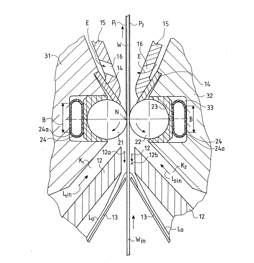
can be adjusted. In accordance with the embodiment of Fig. 2,
discussed belowr the coating substance is introduced through the
ducts Kl and K2 in the direction of arrows Llin and L2in to
the upstream side of the nip N whereupon any excess coating substance
~ n
A~ is passed through the gaps 12a and 12b formed ~et~eee~ the blades 12
~ r~ov~s
in the web Win in the direction of~r~rnt~ Lo, guided by
additional blades 13. ~gain, by adjusting the magnitude of the gap~
\
--6--
~3~ )5
12a and 12b, it is possible to adjust the pressure of the coating
substance which is effective in the nip~ In the embodiment of ~ig,
2, both sides of the web W are coated with coating layers Pl and
P2 respectively as the web is passed through nip. After passing
through the nip, hot air is directed onto the coating layers Pl and
P2 in the direction o~ arrows E ~hrough openings 16 formed in
blades 14 in order to dry ~he coating layers.
Referring to the embodiment of Fig. 1, the coating rod 20 is
supported on a counterpiece 23 through engagement with a
semi-circular counter-surface thereof~ The counterpiece 23 comprises
an elongate member which is sufficiently flexible with respect to its
longitudinal dimension so as to conform with the flexing of the
coating rod 20 to achieve the de~ired linear load distribu~ion in the
nip N. The counterpiece 23 is mounted in a groove 33 formed in frame
part 30 and has a planar outer surface 23a which is engaged by an
outer surface region of a loading hose 24. An opposed surace region
of the hose 24 bears against the bottom surface 33a of groove 33. It
is preferable that the loading hose 24 be constructed so that its
wall is non-extensible so that the leng~h of its circumference is
maintained constant regardles~ of the internal pre~sure within the
hose. For example, a mesh 24a may be embedded within the thickness
of the hose 24.
A linear load of desired magnitude is applied in the coa~ing
nip N by applying a suitable load to the coating rod 20 along its
longitudinal dimension through the 6elective control of the internal
pressure P within the loading hose 24. In order to selectively
variably adjust the load appl~ed to the coatlng rod along its
longitudinal dimension to adjust the transver~e profile of the
7~
quantity of coating substance applied to the web, the bottom surface
33a of groove 33 is composed of a plurality of separate members, each
of which can be displaced towards and away from the bearing surface
23a of counterpiece 23 separately from the other parts in order to
compress opposed regions of the loading hose 24. In this manner, the
degree o~ flatness of the hose can be varied thereby adjusting the
length, designated B, of the surface area of surface 23a of
counterpiece 23 on which the hose 24 bears and through which the
pressure P is transmitted to thereby obtain a desired variation in
th~ distribution of the linear load applied to the coating rod 20.
The loading ~orce thereby applied is proportional to the product P x
B x L, where L is the length of hose portion loaded.
In the embodiment of Fig. 2, a pair of opposed ~lexible
blade rods 21 and 22 form the coating nip N. The rods are supported
by respective counterpieces 23 in respective grooves 33 provided in
the frame parts 31 and 32. The coun~erpieces 23 are loaded by hoses
24 in the same manner as described above in connection with Fig. 1 so
that an adjustable distribution of the linear load in the nip N i8
obtained or the purpose of adju~ting one profile of the quantity of
the coating substance applied to the web.
Referring to Figs. 3 and 4, an embodiment of rod coating
apparatus in accordance with the invention is illustrated by means of
which the transverse loading profile applied to the rod 20 can be
precisely controlled. The ¢oating rod 20 i~ supported by a flexible
intermediate or counterpiece 23A mounted in the rame part 30.
The flexible counterpiece 23A i~ e~gaged along its longitudinal
p/ur~ li y o~
dimension by the ends of a i~iFW~LP~r~ loading levers 25 which are
situated in side-by-side relationship in a dire,ction transverse to
~ 3 ~ 7 ~ S
the direction of web movement through the apparatus- As seen in
Fig. 4, the surface regions 28 at the other ends of levers 25 are
engaged by a loading hose 29 which is captured in position by a frame
part 27 to which a support member 15 for a doctor blade 14 is
attached. The support part 15 for doctor blade 14 may be provided
with its own loading hoses 17a and 17b (Fig. 4) by means of which it
is possible to adjust the force applied by the doctor blade 14
against coating rod 20.
The distribution of the linear load in the nip N in the
embodiment of Figs. 3 and 4 in the direction of the longitudinal
dimension of rod 20 is controlled by suitably adjusting the lever
ratio Ll/L2 of each of the levers 25. This is accomplished by
shifting fulcrums 26 o~ levers 25 in the directions of arrow C (Fig.
3). Each lever 25 is therefore preferably provided with its own
fulcrum 26 which rests on the bottom 33A of groove 33. In this
manner, a constant loading force produced by the loading hose 29 is
translated into a loading force on coating rod 20 which is
selectively variable in the direction of the longitudinal dimension
of rod 20. Of course, suitable devices (not shown) are provided for
shifting the respective fulcrums 26~
Referring now to Fig. 5, an arrangement by which the coating
rod 20 is mounted for coating the web W running over roll 10 is
illustrated. The rame part 30 in which the coating rod 20 (or other
coating member of the type described below) is attached to a beam 40
which extends over the entire width o the web. The beam 40 is
attached to the f rame part of the coating apparatus by meanB of
hori~ontal articulated joints 41 80 that it can be pivoted, and
possibly loaded, against roll 10 by conventional power units. The
blade 12 is attached to a frame part 43 which i~ al80 connected to
~ 3 ~ 7 ~ ~
frame beam 40 by means of horizontal articulated joints 44. The
position of the frame part 43 can be adjusted by actuating means 45
to control the size o~ the gap 12a (Fig. 1) to thereby control the
pressure that prevails in the coating substance in front of nip N.
It will be understood that the particular frame arrangement
illustrated in Fig. 5 is described only by way of example so as to
provide an understanding of the construction of the apparatus in its
entirety.
- Referring to Figs. 6 and 7, embodiments o~ rod coating
apparatus in accordance with the invention are illustrated wherein
the means for selectively variably ad justing the load applied to the
coating rod along its longitudinal dimension are illustrated in
detail. ~n elongate unitary flexible intermediate part 37 is
situated in the lower part of groove 33 extending in the direction of
the longitudinal dimension of the coating rod 20. The outer surface
of the flexible intermediate member 37 bears against a surface of the
loading hose 24. A plurality of pusher elements 38 are situated in
side-by-side reitionship with an upper surface of each bearing
against an opposed surface region of intermediate member-37. The
pusher elements 38 are slidable within extensions of the groove 33.
~ach of the pusher elements 38 is associated with a respective
adjusting ~crew 39 received in threaded bores 39' formed in frame
part 30. It will be seen that through the adjustment of the screws
39, it is possible to adjust the length B of the surface counterpiece
23 against which loading hose 24 bears. Accordingly, it is possible
to adjust the distribution o the loading force and, consequently,
the distribution of the quantity of the coating substance applied to
the web, such distribution bèing afected to some extent by the
spacing of the screws 39 and by the flexibility of the contact rod
20, counterpiece 23 and intermediate member 37.
_10-
~3 [)~ 5
Referring to Fig~ 7, an embodiment of rod coating apparatus
in accordance with the invention is illustrated wherein provision is
made for washing the coating rod 20 as it rotates in khe counterpiece
23. The washing means include an lnlet pipe 46a formed in frame part
54 through which wash water is provided. Several distribution pipe~
47a co~nunicate with inlet pipe 46a, the dis~ribution pipes supplying
wash water from inlet pipe 46a into a pipe 48a embedded in
~ o~ IqlC~
counterpiece 23. Passages ~9a eff~ eYh~ with pipe 4~a and open
into grooves 50 formed in counterpiece 23. The grooves 50 have a
suitable pitch with respect to the direction of rotation o~ the rod
20 so that the wash water passing throught the grooves 50 flush and
wash the entire outer surface of the rod 20. The wash water is
passed from the grooves 50 back through passage~ 49b into a pipe 48b
embedded in the counterpiece 23 and from there through a di~tribution
pipe 47b into a water discharge pipe 46b~
Still referring to Fig~ 7, the counterpiece 23 o~ coating
rod 20 is supported by flexible plates 52a and 52b between the frame
part 30 and the projecting part 54. A pressure hose 51 may be used
to provide a resilient fastening of the part 52a between parts 30 and
54. Such mounting also enables a slight shifting of the part 52a in
the direction of itB plane both upwardly and downwardly when the
counterpiece 23 is loaded by loading hose 24 and when the
distribution of the loading force in the direction of the
longitudinal dimension o~ coating rod 20 i8 being set by adjusting
screws 39 in the manner described above.
Referring now to Fig. 8, an embodiment of blade coating
apparatus in accordance with ~he invention is illustrated including a
-11- ?
~3~
coating blade 60 forming a coating nip N with the surface 10' of
counter roll 10. The coating blade 60 is loaded against the counter
roll 10 by means of a loading hose ~4 directly engaging the same.
The loading hose is itself loaded by means of a unitary intermediate
member 37, a plurality of pusher elements 38 situated in a manner
as described above in connection with Fig. 6, and respective
adjusting screws 39. The siæe or other coating ~ubstance is supplied
to the duct ~ in the direction of arrow ~in to the upstream side of
the blade 60. A blade 61 mounted on a blade 12 forms a gap 62 with
coun~er roll 10 that restricts the overflow Lo of the size thereby
determining the pressure prevailing in the size upstream of nip N.
Referring to Fig. 9, an embodiment of coating apparatus in
accordance with the invention wherein the coating member comprises a
member 70 for smoothing the cvating is illu~trated, The smoothing
member 70 comprises an elongate member having an outer part which i~
curved, i.e., has a convex cross-section in a plane perpendicular to
its longitudinal dimen~ions, the outer part 71 forming a ~moothing
nip with the counter roll 10. The curved outer part 71 preferably
has a circular section configuration and a projecting plate-zhaped
arm portion 73 extends from outer part 71, the smoothing member 70
being connected to the frame part 30 by the projecti~g part 73.
Referring to Fig. 9 in conjunction Figs. lOA to
lOC,reinforcement ribs 72 are provided at the inner sides of the
convex outer part 71 and the spaces between the ribs 71 are filled
with a suitable mass. In the embodiment of ~ig. lOA and lOC the
curved outer part 71 is attached to the plate-shaped projecting
portion 73 by means of rivets or screws 74 with the projecting part
-12-
~ 3 ~
73 being attached to ~he frame part 30 as shown in Fig. 9. As seen
in Fig. 9, a duct ~ is formed in part by projecting part 73 through
which size is supplied~ designated by arrrow Lin~ to a region
Ct 1~1G~
~A~ upstream of the nip N de~ined by the counter roll lO inrth0 smoothing
member 70. In the embodiment o~ Fig. lOD, a reinforcement part 72A
formed of solid material is provided ln conjunction with the curved
outer part 71. In the embodiment of Fig. lOE, the smoothing member 70
comprises a plate-shape arm or pro~ecting part 73 at the end of which
a tubular part 71A is provided which defines the nip N with the
counter roll lO.
Referring to Fig. 11, an arrangement for loading a smoothing
member 70 of the type described above so as to provide for a
selectively variably adjustabla proile of the loading force applied
in the nip N in the ~ransverse direction with respect to the
direction of web movement is illustrated. The illustrated
arrangement is similar to that de~cribed above in connection with the
blade-coating device of Fig. 8. In particular, the loading hose
directly engages the surface region of the smoothing member 70 while
a un~tary elongate flexible intermediate member 37 bears against the
other side of the loading hose 24. A plurality of pusher elements 38
arQ spaced in side-by-side relationship in the transverse direction
and are associated with respective threaded members 39 to apply the
selectively variably load to the smoothing member~
Referring to Fig, 12, an embodiment o~ the invention is
illustrated in which two smoothing members 70 are situated in opposed
relationship to each other to form a nip N between them. The
smoothing members used in the apparatus illu~trated in Figs. 9-12 are
formed, for example, of polya~etal or e~uivalent material which can
-13-
~3(~7~
be coated, if necessary, to render the same wear-resistant.
For example, the smoothing members may be provided with a
ceramic coating prepared by spraying a wear-resistant surface
layer onto the frame part.
The loading hoses 24 of Fig. 12 bear against the planar
portions of the reinforcing means provided on the outer
convexly-curved part 71. ~he device shown in Fig. 12 is in
other respects similar to the embodiment shown in Fig. 2 with
the distribution of the loading pressure on the smoothing
members 70 controlled by means of adjusting screws 39~
An important parameter which affects coating of a web by
a blade coater is the so-called blade angle, namely the angle
formed between the plane of the coating blade and a plane
tangential to the nip. A sufficiently steep adjustment of
`15 the profile of the linear load in the coating nip N is
advantangeously accomplished by means of devices in
accordance with the invention so that the blade angle is not
changed to a substantial extent during adjustment of the
profile of the linear load even over relatively wide ranges
of adjustment.
.,
~ -14-
. .
.