Note: Descriptions are shown in the official language in which they were submitted.
` 1 307~n3
Method for Stringing A Game Racket With Vertical
and Diagonal Sets of Strings and Strunq Racket
Background of the Invention
1. Area of Invention
-
This invention relates to game rackets and, in
particular, to rackets having three (3) sets of strings and
to a method for stringing them.
2. Prior Art
Numerous arrangements have been proposed for using
diagonal sets of strings in game rackets. For example,
British Patent No. 5177 to Nightingale shows two sets of
diagonals used with one set of horizontal strings. V.S.
Patent No. 3,917,267 show two sets of diagonals serving as
the entire stringing pattern. Other patents have shown
- diagonal stringing together with vertical strings such as
British Patent No. 224,~64 to Forbes.
Non-uniform spacing and non-parallel string sets are
seen in British Patent No. 10,851 to Forrester and U.S.
Patent ~o. 1,687,322 to Claremont.
U.S. Patent No. 4,184,679 to Mishel shows diagonals
employed with both horizontal and vertical sets of strings.
Each set of strings is strung with a separate length of
string.
Summary of the Invent_on
Broadly, the present invention comprises a method of
stringing a handled game racket with three (3) sets of string
sections using a length of string, prefera~ly an integral
length, in which a set of vertical string sections substan-
tially parallel to the handle is started with a length of
said string by stringing a portion of the head starting with
3 the longer string sections and upon reaching shorter string
sections the same length is employed to create an initial
'
1 307~03
number of string sections in a first set of diagonal sections.
Another length of the string is used to complete the vertical
string sections and start a second diayonal set. Finally,
the string length that is-used to create the initial string
sections in one diagonal set is used to finish the other
diagonal set. The racket frame has a plurality of holes or
other string support means positioned along the frame to
support the string sections. The string portion used to
form the part of each diagonal set is passed by a plurality
of holes or other string supports to form part of the other
diagonal set. More or less, corresponding diagonals in
opposite directions are alternatively threaded thereon.
It is a feature that one ntegral length of string
or a series of connected lengths may be used in this method
providing a simple and convenient way of stringing.
It is also a feature that this method may be used
on a variety of game rackets including round, oval and
other shaped frames.
Brief Description of the Drawings
F~g. l is a partial front elevational view of the
game racket strung in accordance with the present invention;
Fig. 2 is a similar elevational view with right
verticals strung;
Fig. 3 is a similar elevational view with all verti-
cals completed and the first string section of a set of
diagonals being threaded;
Figs. 4-6 are similar elevational views with addi-
tional diagor.al string sections completed
Fig. 7 is an enlarged view of a portion of the
stringing of Fig. l showing the string weave; and
Fig. 8, shows a view similar to Fig. 7, with an
alternative weave.
1 3073n:~
Description of a Preferred Embodiment
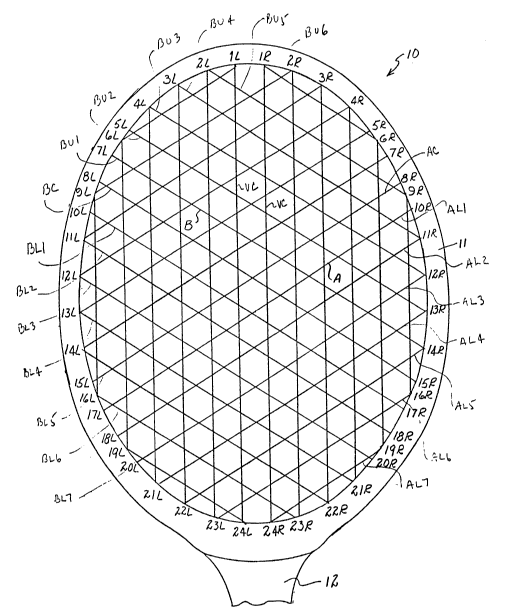
Referring to Fig. 1, tennis racket 10 includes
frame 11 and handle 12. The racket is strung with a length
of string to form three (3) sets of string sections; a
vertical set of strings (which are substantial'ly parallel
to the handle 12) a diagonal set of strings-A and a second
set of diagonal strings B. Forty-eight holes lL-24L and
lR-24R are formed in frame ll suitably spaced to position
the vertical and diagonal sets as shown and hereinafter
described. Holes lL-24L and lR-24R are tubular passage holes.
Each hole is non-uniformly spaced along the frame 11 to pro-
vide the pattern shown and each hole is generally radially
oriented with respect to the frame. The spacing of the holes
- is selected to create the vertical (parallel to handle 12)
sections and the sets of diagonals as shown in the drawings
in which the diagonal strings intersect midway between the
vertical strings. Other types of supporting string means
such as hoo~s, loops or grooves may be used. When holes in
the frame are used, the position of the ends of string
sections are determined by the location of the outlets of
holes along the interior of frame.
Referring now to Figs. 2-6, a length of string (S)
is strung to form the long~r verticals in the center (VCs).
After forming the two (2) center verticals (VCs), string
portion 17 of string (S) is thereafter strung to complete
the right vertical string sections VRl, VR2, etc. In Fig.
~ 2 string portion 17 is shown strung to complete six (6) right
verticals (VC and VRl 5) while string portion 18 has not yet
been strung to form the left vertical sections. Preferably
string portions 17 and 18 are of approximately the same
length before stringing begins.
"`` 1 30~3n3
Turning to Figs. 3 and 4, center diagonals AC and
BC are shown being formed with lengths of string portions 17
and 18, respectively. ~iagonal AC appears as a solid line
because it passes in front of (over) the vertical lengths
while diagonal BC appears as a dashed line because it passes
behind (under) the vertical sections. B diagonals pass in
front of A diagonals (see Fig. 7) or, in an alternative
embodiment, A diagonals may pass in front of B diagonals
(see Fig. 8). Additional string sections, AUl luPper 1),
AU2, etc. and BUl, BU2, etc. are thereafter alternatively
formed to commence completion of the upper diagonal groups
(see Fig. 5).
Upon completion of AUl-AU6 from a length of string
portion 17, portion 17 is further strung through hole lOL
to provide BLl (lower 1) and successive BL string sections
to complete the B set of diagonals. Likewise, upon comple-
tion of BUl-BU6, string portion 18 is then strung through
hole lOR to form diagonals ALl and with further threading
AL2-7 to complete the A set of diagonals. The preferred
stringing pattern is to string one diagonal in set A and
then a corresponding diagonal in set B so that the tension
forces applied to the frame are substantially balanced.
This balancing of forces prevents distortion of the frame thus
maintaining its integrity. If desired the lower A string
sections and lower B string sections may be strung before
the upper A or B string sections.
Turning again to Fig. 6, it is seen that string
portion 17 upon completion of AU6 at hole 6L is then caused
to by-pass holes 7L, 8L and 9L (see Fig. 1) before it is
threaded through lOL to form string section BLl. String
portion 17 is shown in dashed line in Fig. 6 as it resides
in a recess in frame 11. It is seen that strinq portion 17
1 307303
--5--
.
by-passes holes 7L, 8L and 9L in that it does not form any
string sections from ~with respect to) such holes. String
18 is similarly threaded.
In alternative embodiments of the invention, the
string sections (V) may be strung at a.n angle to the handle
such as a ninety degree ~90) angle (see handle 12'; Fig. 4).
In these embodiments, the parallel set of strings oriented
at such angle to the handle are threaded in any desired
sequence including shorter string sections before longer
string sections and including, where all such sections are
of equal length, the threading of sections further from
the frame before the sections closerto the frame.