Language selection

Search

Patent 1307390 Summary

Third-party information liability

Some of the information on this Web page has been provided by external sources. The Government of Canada is not responsible for the accuracy, reliability or currency of the information supplied by external sources. Users wishing to rely upon this information should consult directly with the source of the information. Content provided by external sources is not subject to official languages, privacy and accessibility requirements.

Claims and Abstract availability

Any discrepancies in the text and image of the Claims and Abstract are due to differing posting times. Text of the Claims and Abstract are posted:

  • At the time the application is open to public inspection;
  • At the time of issue of the patent (grant).
(12) Patent: (11) CA 1307390
(21) Application Number: 1307390
(54) English Title: SAFETY RAZORS
(54) French Title: RASOIRS ASSURANT UNE PROTECTION ACCRUE
Status: Expired and beyond the Period of Reversal
Bibliographic Data
(51) International Patent Classification (IPC):
  • B26B 21/40 (2006.01)
  • B26B 21/22 (2006.01)
(72) Inventors :
  • FRANCIS, JOHN FREDERICK (United Kingdom)
(73) Owners :
  • THE GILLETTE COMPANY
(71) Applicants :
  • THE GILLETTE COMPANY (United States of America)
(74) Agent: MACRAE & CO.
(74) Associate agent:
(45) Issued: 1992-09-15
(22) Filed Date: 1988-04-28
Availability of licence: N/A
Dedicated to the Public: N/A
(25) Language of filing: English

Patent Cooperation Treaty (PCT): No

(30) Application Priority Data:
Application No. Country/Territory Date
87 10963 (United Kingdom) 1987-05-08

Abstracts

English Abstract


ABSTRACT
A razor formed as a unitary moulding comprises a
main body 1 including a cap member 3 and two side walls 4
and a guard member 6 connected to the body 1 by spring
fingers 7 and living hinges which permit the guard member
to be located in guide means 9 which guide the guard
member for limited displacement during shaving.


Claims

Note: Claims are shown in the official language in which they were submitted.

- 4 -
CLAIMS:
1. A razor head comprising a main body having
location means for receiving elongate blade means and a
guard member which is resiliently displaceable in
reaction to forces encountered during shaving, the said
main body and guard member being formed as a unitary
plastics moulding in which the guard member is connected
to the main body by resilient fingers and living hinges
which together permit the guard member to be displaced
relative to the main body from an original position as
moulded, into engagement with guide means on the main
body, the said guide means permitting displacement of the
guard member against the restoring action of the
resilient fingers.
2. A razor head according to claim 1, wherein the
main body comprises a rear wall having a skin-engaging
cap surface and forwardly projecting, opposite side
walls, the said fingers projecting forwardly from the
rear wall and being connected to the said guard member by
living hinges, and wherein the said guide means are
formed at the forward ends of the said side walls to
define guide slots open from above, the guard members
being engageable in the said slots by flexure of the said
fingers and of the said hinges.
3. A razor head according to claim 2, wherein the
main body and guard member are formed with co-operating
abutment means which are interengaged when the guard
member is engaged in the guide means, the said abutment
means serving to limit displacement of the guard member
relative to the guide means.

Description

Note: Descriptions are shown in the official language in which they were submitted.


~ 3~ 7 ~9~
SAFETY RAZORS
This invention relates to safety razors, and in particular
to razor heads, or cartridges, having guard members which are
resiliently displaceable in reaction to the forces encountered
during shaving.
Razor heads or cartridges of this form are described, for
example, in British Patent Specifications 1566505, 2131337 and
2064410.
The present invention is particularly concerned with the
construction of a cartridge body which permits of its being
formed as a unitary plastics moulding incorporating the guard
member and spring means for its resilient mounting relative to
the main body of the cartridge.
In the cartridge described below, the guard member, in the
form of an elongate bar, is integrally connected to the rest of
the body by resilient fingers incorporating living hinges
permitting the bar to be displaced from its original moulded
position into engagement with guide means in the body, so that
the bar is resiliently displaceable relative to the rest of the
body in use of the cartridge.
The present invention may thus be considered as providing
a razor head comprising a main body having location means for
receiving elongate blade means and a guard member which is
resiliently displaceable in reaction to forces encountered during
shaving, the main body and guard member being formed as a unitary
plastics moulding in which the guard member is connected to the
main body by resilient fingers and living hinges which together
permit the guard member to be displaced relative to the main body
from an original position as moulded, into engagement with guide
means on the main body, the guide means permitting displacement
of the guard member against the restoring action of the resilient
fingers.
The invention will now be described in detail, by way of
example with reference to the accompanying drawings, in which:
Fig. 1 is a perspective view of the cartridge body "as
moulded";

,. ~ 13~q7;~
~ g&. 2 8nd 3 ~re end ~iew~ 6howin~ thc
guard bar in it~ moulded and its s6~embled pG~itiOnS,
respectively;
~ ig. 4 i~ an exploded per6pecti~e ~iew of the
S completed cartridge body and a tandem blade unit for
mounting therein) and
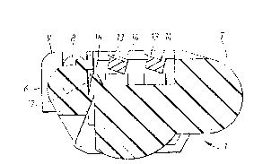
Fig. S is a cross-section of the a6sembled
cartridge.
Fig. 1 6ho~ the integrally m~ulded cartridge
bod~ ~ in its condition "as moulded". It compri~es:
a rear wall 2, whose upper surface 3 is destined to form
a cap to the rear of the blades; opposite side walls 4;
and a guard bar 6 integrally connected to the rear wall
by ~pring fingers 7. The ends of the bar 6 are provided
with projecting pins 8 for eventual location in guide
brackets 9 at the forward ends of the ~ide wall6 4.
~ s best 6een in Figs. 2 and 3, the junctions
between the free ends of fingers 7 and the guard bar 6
are of reduced cross-section to form living hinges 11.
After moulding, the guard bar is ~wung upwardly, in an
anti-clock~içe direction (as viewed in ~igs. 2 and 3),
to bring the pins 8 up and over the brackets 9, with
60me re~ilient deflection of the 6prin~ finger~ 7, to
a6sume the assembled position 6een in ~ig. 3, in which
the pins are guide~ for movement relative to the rest
of the cartridge body in a vertical direction, assuming
the cartridge to be in a hori~ontal attitude.
~ s illu~trated in ~ig. 4, the cartridge body
now forms a generally rectangular open frame for reception
and location of a blade unit 12,-formed in thi6 example
by ~ pair of narrow blade 6trips 13 each 6ecured to
wire like 6upports 14 held in 6paced parallel relation
by end clips 16. The6e clips ~re secured with the rart-
ridge and proYide for re~ilient ~ounting ~f the blade6
which are independently ~prung 60 a~ to be ~rged

13~3
- 3 --
upwardly but di6placeab~e downwardly in re6pon6e to
forces encountered during 6having.
Fig. 5 6how6 a cross-6ection of the a~sembled
cartridge and a notional tangent plane T containing the
upper 6urface~ of the guard bar in a medial po~ition and
cap. In use of the cartridge, each of the blade6 ~nd
guard bar are resiliently displaceable downwardly in
directions perpendicular to the tangent plane T in response
to forces encountered during shaving.
As best seen in Fig. 5, upward movement of the
guard bar 6 is limited by the interengagement of projections
17 at the front of the body 1 in circular recesses 18 formed
in the inner 6urface of the bar 6.
It will be understood that the term ~ertically and
horizontally are employed herein for the purposes of
description and that the cartridge will adopt many different
attitudes in use.

Representative Drawing
A single figure which represents the drawing illustrating the invention.
Administrative Status

2024-08-01:As part of the Next Generation Patents (NGP) transition, the Canadian Patents Database (CPD) now contains a more detailed Event History, which replicates the Event Log of our new back-office solution.

Please note that "Inactive:" events refers to events no longer in use in our new back-office solution.

For a clearer understanding of the status of the application/patent presented on this page, the site Disclaimer , as well as the definitions for Patent , Event History , Maintenance Fee  and Payment History  should be consulted.

Event History

Description Date
Inactive: IPC from MCD 2006-03-11
Time Limit for Reversal Expired 2000-09-15
Letter Sent 1999-09-15
Grant by Issuance 1992-09-15

Abandonment History

There is no abandonment history.

Fee History

Fee Type Anniversary Year Due Date Paid Date
MF (category 1, 5th anniv.) - standard 1997-09-15 1997-08-13
MF (category 1, 6th anniv.) - standard 1998-09-15 1998-08-04
Owners on Record

Note: Records showing the ownership history in alphabetical order.

Current Owners on Record
THE GILLETTE COMPANY
Past Owners on Record
JOHN FREDERICK FRANCIS
Past Owners that do not appear in the "Owners on Record" listing will appear in other documentation within the application.
Documents

To view selected files, please enter reCAPTCHA code :


To view images, click a link in the Document Description column. To download the documents, select one or more checkboxes in the first column and then click the "Download Selected in PDF format (Zip Archive)" or the "Download Selected as Single PDF" button.

List of published and non-published patent-specific documents on the CPD .

If you have any difficulty accessing content, you can call the Client Service Centre at 1-866-997-1936 or send them an e-mail at CIPO Client Service Centre.


Document
Description 
Date
(yyyy-mm-dd) 
Number of pages   Size of Image (KB) 
Cover Page 1993-11-04 1 10
Abstract 1993-11-04 1 8
Claims 1993-11-04 1 31
Drawings 1993-11-04 2 28
Descriptions 1993-11-04 3 96
Representative drawing 2000-07-13 1 6
Maintenance Fee Notice 1999-10-13 1 178
Fees 1996-08-19 1 66
Fees 1995-08-21 1 81
Fees 1994-06-17 1 79