Sélection de la langue

Search

Sommaire du brevet 1307390 

Énoncé de désistement de responsabilité concernant l'information provenant de tiers

Une partie des informations de ce site Web a été fournie par des sources externes. Le gouvernement du Canada n'assume aucune responsabilité concernant la précision, l'actualité ou la fiabilité des informations fournies par les sources externes. Les utilisateurs qui désirent employer cette information devraient consulter directement la source des informations. Le contenu fourni par les sources externes n'est pas assujetti aux exigences sur les langues officielles, la protection des renseignements personnels et l'accessibilité.

Disponibilité de l'Abrégé et des Revendications

L'apparition de différences dans le texte et l'image des Revendications et de l'Abrégé dépend du moment auquel le document est publié. Les textes des Revendications et de l'Abrégé sont affichés :

  • lorsque la demande peut être examinée par le public;
  • lorsque le brevet est émis (délivrance).
(12) Brevet: (11) CA 1307390
(21) Numéro de la demande: 1307390
(54) Titre français: RASOIRS ASSURANT UNE PROTECTION ACCRUE
(54) Titre anglais: SAFETY RAZORS
Statut: Périmé et au-delà du délai pour l’annulation
Données bibliographiques
(51) Classification internationale des brevets (CIB):
  • B26B 21/40 (2006.01)
  • B26B 21/22 (2006.01)
(72) Inventeurs :
  • FRANCIS, JOHN FREDERICK (Royaume-Uni)
(73) Titulaires :
  • THE GILLETTE COMPANY
(71) Demandeurs :
  • THE GILLETTE COMPANY (Etats-Unis d'Amérique)
(74) Agent: MACRAE & CO.
(74) Co-agent:
(45) Délivré: 1992-09-15
(22) Date de dépôt: 1988-04-28
Licence disponible: S.O.
Cédé au domaine public: S.O.
(25) Langue des documents déposés: Anglais

Traité de coopération en matière de brevets (PCT): Non

(30) Données de priorité de la demande:
Numéro de la demande Pays / territoire Date
87 10963 (Royaume-Uni) 1987-05-08

Abrégés

Abrégé anglais


ABSTRACT
A razor formed as a unitary moulding comprises a
main body 1 including a cap member 3 and two side walls 4
and a guard member 6 connected to the body 1 by spring
fingers 7 and living hinges which permit the guard member
to be located in guide means 9 which guide the guard
member for limited displacement during shaving.

Revendications

Note : Les revendications sont présentées dans la langue officielle dans laquelle elles ont été soumises.


- 4 -
CLAIMS:
1. A razor head comprising a main body having
location means for receiving elongate blade means and a
guard member which is resiliently displaceable in
reaction to forces encountered during shaving, the said
main body and guard member being formed as a unitary
plastics moulding in which the guard member is connected
to the main body by resilient fingers and living hinges
which together permit the guard member to be displaced
relative to the main body from an original position as
moulded, into engagement with guide means on the main
body, the said guide means permitting displacement of the
guard member against the restoring action of the
resilient fingers.
2. A razor head according to claim 1, wherein the
main body comprises a rear wall having a skin-engaging
cap surface and forwardly projecting, opposite side
walls, the said fingers projecting forwardly from the
rear wall and being connected to the said guard member by
living hinges, and wherein the said guide means are
formed at the forward ends of the said side walls to
define guide slots open from above, the guard members
being engageable in the said slots by flexure of the said
fingers and of the said hinges.
3. A razor head according to claim 2, wherein the
main body and guard member are formed with co-operating
abutment means which are interengaged when the guard
member is engaged in the guide means, the said abutment
means serving to limit displacement of the guard member
relative to the guide means.

Description

Note : Les descriptions sont présentées dans la langue officielle dans laquelle elles ont été soumises.

~ 3~ 7 ~9~
SAFETY RAZORS
This invention relates to safety razors, and in particular
to razor heads, or cartridges, having guard members which are
resiliently displaceable in reaction to the forces encountered
during shaving.
Razor heads or cartridges of this form are described, for
example, in British Patent Specifications 1566505, 2131337 and
2064410.
The present invention is particularly concerned with the
construction of a cartridge body which permits of its being
formed as a unitary plastics moulding incorporating the guard
member and spring means for its resilient mounting relative to
the main body of the cartridge.
In the cartridge described below, the guard member, in the
form of an elongate bar, is integrally connected to the rest of
the body by resilient fingers incorporating living hinges
permitting the bar to be displaced from its original moulded
position into engagement with guide means in the body, so that
the bar is resiliently displaceable relative to the rest of the
body in use of the cartridge.
The present invention may thus be considered as providing
a razor head comprising a main body having location means for
receiving elongate blade means and a guard member which is
resiliently displaceable in reaction to forces encountered during
shaving, the main body and guard member being formed as a unitary
plastics moulding in which the guard member is connected to the
main body by resilient fingers and living hinges which together
permit the guard member to be displaced relative to the main body
from an original position as moulded, into engagement with guide
means on the main body, the guide means permitting displacement
of the guard member against the restoring action of the resilient
fingers.
The invention will now be described in detail, by way of
example with reference to the accompanying drawings, in which:
Fig. 1 is a perspective view of the cartridge body "as
moulded";

,. ~ 13~q7;~
~ g&. 2 8nd 3 ~re end ~iew~ 6howin~ thc
guard bar in it~ moulded and its s6~embled pG~itiOnS,
respectively;
~ ig. 4 i~ an exploded per6pecti~e ~iew of the
S completed cartridge body and a tandem blade unit for
mounting therein) and
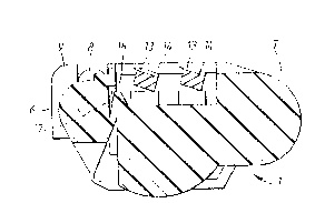
Fig. S is a cross-section of the a6sembled
cartridge.
Fig. 1 6ho~ the integrally m~ulded cartridge
bod~ ~ in its condition "as moulded". It compri~es:
a rear wall 2, whose upper surface 3 is destined to form
a cap to the rear of the blades; opposite side walls 4;
and a guard bar 6 integrally connected to the rear wall
by ~pring fingers 7. The ends of the bar 6 are provided
with projecting pins 8 for eventual location in guide
brackets 9 at the forward ends of the ~ide wall6 4.
~ s best 6een in Figs. 2 and 3, the junctions
between the free ends of fingers 7 and the guard bar 6
are of reduced cross-section to form living hinges 11.
After moulding, the guard bar is ~wung upwardly, in an
anti-clock~içe direction (as viewed in ~igs. 2 and 3),
to bring the pins 8 up and over the brackets 9, with
60me re~ilient deflection of the 6prin~ finger~ 7, to
a6sume the assembled position 6een in ~ig. 3, in which
the pins are guide~ for movement relative to the rest
of the cartridge body in a vertical direction, assuming
the cartridge to be in a hori~ontal attitude.
~ s illu~trated in ~ig. 4, the cartridge body
now forms a generally rectangular open frame for reception
and location of a blade unit 12,-formed in thi6 example
by ~ pair of narrow blade 6trips 13 each 6ecured to
wire like 6upports 14 held in 6paced parallel relation
by end clips 16. The6e clips ~re secured with the rart-
ridge and proYide for re~ilient ~ounting ~f the blade6
which are independently ~prung 60 a~ to be ~rged

13~3
- 3 --
upwardly but di6placeab~e downwardly in re6pon6e to
forces encountered during 6having.
Fig. 5 6how6 a cross-6ection of the a~sembled
cartridge and a notional tangent plane T containing the
upper 6urface~ of the guard bar in a medial po~ition and
cap. In use of the cartridge, each of the blade6 ~nd
guard bar are resiliently displaceable downwardly in
directions perpendicular to the tangent plane T in response
to forces encountered during shaving.
As best seen in Fig. 5, upward movement of the
guard bar 6 is limited by the interengagement of projections
17 at the front of the body 1 in circular recesses 18 formed
in the inner 6urface of the bar 6.
It will be understood that the term ~ertically and
horizontally are employed herein for the purposes of
description and that the cartridge will adopt many different
attitudes in use.

Dessin représentatif
Une figure unique qui représente un dessin illustrant l'invention.
États administratifs

2024-08-01 : Dans le cadre de la transition vers les Brevets de nouvelle génération (BNG), la base de données sur les brevets canadiens (BDBC) contient désormais un Historique d'événement plus détaillé, qui reproduit le Journal des événements de notre nouvelle solution interne.

Veuillez noter que les événements débutant par « Inactive : » se réfèrent à des événements qui ne sont plus utilisés dans notre nouvelle solution interne.

Pour une meilleure compréhension de l'état de la demande ou brevet qui figure sur cette page, la rubrique Mise en garde , et les descriptions de Brevet , Historique d'événement , Taxes périodiques et Historique des paiements devraient être consultées.

Historique d'événement

Description Date
Inactive : CIB de MCD 2006-03-11
Le délai pour l'annulation est expiré 2000-09-15
Lettre envoyée 1999-09-15
Accordé par délivrance 1992-09-15

Historique d'abandonnement

Il n'y a pas d'historique d'abandonnement

Historique des taxes

Type de taxes Anniversaire Échéance Date payée
TM (catégorie 1, 5e anniv.) - générale 1997-09-15 1997-08-13
TM (catégorie 1, 6e anniv.) - générale 1998-09-15 1998-08-04
Titulaires au dossier

Les titulaires actuels et antérieures au dossier sont affichés en ordre alphabétique.

Titulaires actuels au dossier
THE GILLETTE COMPANY
Titulaires antérieures au dossier
JOHN FREDERICK FRANCIS
Les propriétaires antérieurs qui ne figurent pas dans la liste des « Propriétaires au dossier » apparaîtront dans d'autres documents au dossier.
Documents

Pour visionner les fichiers sélectionnés, entrer le code reCAPTCHA :


Pour visualiser une image, cliquer sur un lien dans la colonne description du document. Pour télécharger l'image (les images), cliquer l'une ou plusieurs cases à cocher dans la première colonne et ensuite cliquer sur le bouton "Télécharger sélection en format PDF (archive Zip)" ou le bouton "Télécharger sélection (en un fichier PDF fusionné)".

Liste des documents de brevet publiés et non publiés sur la BDBC .

Si vous avez des difficultés à accéder au contenu, veuillez communiquer avec le Centre de services à la clientèle au 1-866-997-1936, ou envoyer un courriel au Centre de service à la clientèle de l'OPIC.


Description du
Document 
Date
(aaaa-mm-jj) 
Nombre de pages   Taille de l'image (Ko) 
Page couverture 1993-11-04 1 10
Abrégé 1993-11-04 1 8
Revendications 1993-11-04 1 31
Dessins 1993-11-04 2 28
Description 1993-11-04 3 96
Dessin représentatif 2000-07-13 1 6
Avis concernant la taxe de maintien 1999-10-13 1 178
Taxes 1996-08-19 1 66
Taxes 1995-08-21 1 81
Taxes 1994-06-17 1 79