Note: Descriptions are shown in the official language in which they were submitted.
CROP HARVESTER
Background of the Invention
The present invention relates primarily to means
for harvesting standing crops growing in the field and
having a head at the top of the stalk such as wheat.
In particular, the present invention relates to a
system for combining or stripping the grain from the
stalk leaving the stalk substantially in the field and
performing cleaning operations on the grain after
stripping before depositiny in a grain wagon for
departure from the field. Harvesting of standing crops
by ~ingers, drums and brushes has been attempted for
many years and is shown in various forms in the prior
art. One such combine is shown in my U.S. Patent
A ~ r-~*~--t~- ~,13g,0g7 . Similar harvesters are shown
in U.S. Patent 3,184,904; 2,853,845 and 2,547,749. In
the prior art there has not been any system which has
been a commercial success because grain losses are high
and the harvested grain still has been sent through the
regular combine apparatus to clean and continue the
separation of the grain from the chaff and straw. Part
of the reason for this lack of success was that the
prior art strippers did not strip only the area of the
1307401
heads as they sa~ upon the stalk but rather stripped
too much of the stalk. This was partly due to the fact
the header was not accurately positioned to limit its
stripping action to the area of the heads. An
important improvement was my U.S. Patent 4,507,910
which had an automatic sonar heighth control for
headers. However, this invention improved the
placement of the header but only had the known top
stripping action which did not necessarily reach all of
the grains as they existed on the head at the top of
the stalk. This present invention provides for the
control of a plurality of stripping means for threshing
of the grain from the stalk. By utilizing two heads or
two stripping means, it is possible to strip almost all
the grain from the straw forming the stalks. The two
stripping actions may be and are confined to the area
on the stalk which contains the heads and do not attack
or remove any of the straw from the field. This
invention in addition provides for a novel stripping
means. The auger stripper with v-shaped notches or
wedges cut in the flighting provides the improvement in
stripping by having impact for shattering the heads to
remove the grain from the stalk plus having a pulling
action which will assist in rernoving the head and the
grain from the stalks. The prior art has also been
plagued by the problem of providing a means of
transporting the grain from the stripper to the
carrying means. This has normally been done by sending
the grain through the separator and cleaner of a
combine and then into the grain tank of the combine.
This was also believed necessary in the prior art in
order to clean the grain and to ensure adequate
separation of all of the grain. This invention has an
air flow system which improves the separation of the
grain from the stalk at the point of stripping and
provides for cleaning after stripping and also provides
:1.3(~40~1
-- 3
the transport means for transporting the grain which
has been removed from the stalk to ~he cart or carrying
mechanism for storing the grain to remove i~ from the
field.
Sumrnary of the Invention
It is therefore a principal object of the present
invention to provide a crop harYesting combine
including control system and a threshing system which
permits the stripping threshing concept the most
precise contact with the grain heads of the crop to be
harvested. In particular, it is an object of this
invention to provide a harvesting system which will
harvest the standing grain crop with particular
attention to the stripping of the grain by the use of a
heighth control system, stripping system and an air
flow system tilat in combination provides a total
threshing and improved cleaning system for small
grains. This and additional objects of the present
invention are achieved by providing an automatic
heighth control system applied to a two stripper
concept which ensures that the upper and lower stripper
are operating strictly within the grain head area.
This also ensures that the total crop is stripped from
the stalk as the combine proceeds down the field. The
crop harvesting system also employs an air flow that
forces tlle stalks of the standing crop into positive
contact with the stripping mechanisms. The system
utilizes the e~haust air both from the air flow system
and the action of the stripper's rotation. This total
air flow takes the waste material, i.e., chaff and
straw to a cleaning mechanism where the waste material
can be removed and deposited on the ground. A second
air system is utilized to assist in the movement of the
grain and heads removed from the straw stalks through a
second threshing system and then to carry the grain
~3V7~0~
~ 4 --
from the secon(l threstling systeln to a depositor~
location. The strippiny mechanism employed in one
embodiment of this invention is also a novel threshing
system. This stripping mechanism is an auger having a
flighting which flighting is directed toward the middle
and is in two parts and having v-shap~ed wedges in the
flighting. These v-shaped wedges are able to provide
positive separation of the grain from the stalks by
both impact and a stripping action at the apex of the v
shape. The positioning of the header of this
harvesting system is achieved by hydraulics responding
to the sonar sensors and to the heighth sensing system
for positioning the stripping mechanisms accurately
with respect to the grain head's position on the stalk
of the growing grain. Additional features and objects
and objectives of the present invention will become
apparent from the following detailed description taken
together with the accompanying drawings.
_he Drawin~
Fig. 1 is a diagramatical left hand view of the
invention mounted on a farm implement for transport
witll the header combined of the present invention
mounted thereon.
Fig. 2 is a front view of the invention
illustrating the novel stripping mechanism of this
invention,
Fig. 3 is a detailed view of the separation and
cleaning portions of the present invention.
Fig. 4 is a cross section of Fig. 3 the plane of
which is indicated by lines 4-4.
Figs. 5 and 6 are simplified views of the header
showing the relative position of the stripping
mechanisms at both extreme positions.
Fig. 7 is a cross-sectional view of Fig. 8; the
plane of which is indicated by lines 7-7.
Fig. 8 is a schematic diagram il lustr~ting the air
flow around the cleaning sy~tem and the air flow of the
transporting system.
Fig. 9 is a schematic diagram illustrating the
present invention stripping grain from short stalks.
Fig 0 10 is a schematic diagraln illustrating the
present inven~ion stripping grain from tall stalks.
Fig 11 is a schematic ~iew oE the second
separation system of the present invention.
Fig. 12 is a schematic view of an alternative
stripping mechanism which can be used in the present
invention
Description of the Preferred Embodiment
_ __
ln accordance with the present invention, an
agricult4ural vehicle such as the windrower is provided
with a header unit. The header unit comprises a
complete threshing element. The system includes
automatic heighth controls to control the header with
respect to the ground surface and the top of the crop
immediately ahead of the combine unit. A diagramatic
view of a typical windrower having a header unit with
the teachings of this invention is attached to the
front end as shown in Fig. 1.
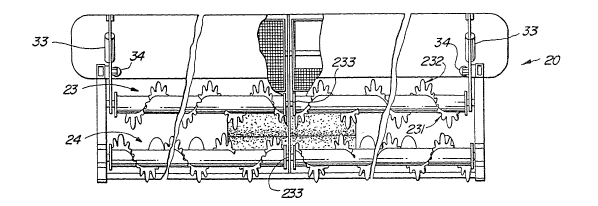
As illustrated, the mobile body (15) is shown with
its propulsion system and may be of any desired mobile
propulsion unit such as a tractor or a ~orage harvester
or windrower as illustrated in ~ig. 1. As
schematically shown in Fig. 1, the mobile body and the
combine header (20) are attached in the normal manner
at (14). This mounting will permit vertical movement
of the header for transport and for adjustment in the
field. This is a noLmal mounting oE a header and the
details are not shown herein. The combine header
includes of a sensor (21) mounted on the deflector
shields or the adjustable shields (22). This sensor is
preEerably of the type described in my UAS. Patent No.
4,507,910 and will continuously control the heighth of
the header in response to the heighth of the crop over
which the header is operating. Shield (22) is
adjustable by means of the adjustment mechanism (32) to
vary the air ~low which is created between the shield
and the stripping element by the rotation of the upper
stripping element (~3). By moving the shield (22)
closer t~ the uppe~ stripping ele~ent (23) a controlled
increase in the amount of air flow can be generated if
necessary to ensure the threshing action by the upper
and lower stripping elements. Upper stripping element
(23) is a split cylinder or auger mounted at the
midpoint and at the sides of the header. The auger
flighting is such that a reverse flow action is
provided at the center of the harvester. ThiS reverse
flow aids in the stripping or percussion action and
also creates the necessary air ~low to prevent crop
buildup at the center of the header. The novel
elements of this auger and the flighting thereon are
that the flighting has a plurality of v-sections cut
into the flighting. These v-sections (232) are cut
into the flighting (231) in order to improve the impact
or percussion stripping of the grain from the stalk as
well as providing a slot action which will perform a
physical stripping if the percussion or impact has not
loosened the grain from the stalk. The size and shape
of the v-section may be varied to accommodate various
crop requirements. Both stripping elements (23) and
(24) are similarly constructed and the lower stripping
element attacks the bottom of the heads of the grain in
a manner similar to that of the upper stripping
element. Grain having been removed from the heads is
transported by the air flow created by the rotating
motions of the stripping elements (23) and (24) and
especially element (23). The air generated between the
'79LO~
~ 7 _
element (23) and the shield (2'~) moves the grain
rearwardly into the chamber (37). It is to be noticed
that the air flow around the upper stripping element
(23) is designed to cause as much of the crop as
possible to be forced onto the lower stripping element
(24) to ellsure total sep~r~tiorl of the grain. The
angle of operation and the heighth control i5 the
function of the entire combine assembly but is
essentially controlled by element (38) which is
normally a hydraulic cylinder. This hydraulic cylinder
causes the header to pivot about points (35) and (36)
as best illustrated in Figs. 9 and 10. The stripping
action and the air flow are controlled as to position
on the stalk by the distance measuring instruments (21)
and the associated mini-computer connected thereto.
The distance measuring instruments and the minicomputer
must provide for an adjustable gate distance between
the upper and the lower stripping elements. This
adjustable gate distance is required in order to ensure
that the stripping elements are positioned at the top
of the head and at the bottom of the head of grain on
the stalk. This gate distance is normally set into the
mini-computer by the operator depending upon the
average size oE the grain head in the field. If the
median distance is 10 inches from the ground for the
heads then the gate may be set for 8-12 or any other
number which will ensure that all heads are stripped by
either the upper or lower element. The stripping
function is the reverse of what you would normally
3Q expect from a study of the prior art, that is the lower
or bottom stripping element performs the majority of
the threshing or stripping of the grain. ~ny grain
that is not collected or threshed by the bottom
stripping unit is automatically forced into the top
stripping element. This occurs when the air flow is
overloaded, i.e., that it cannot push the grain down
4(~1
into the lower stripping elernent or when the density of
the crop is such that the lower stripping element is
overloaded. In thi~ instar-ce, the upper stripping
element then will pick up the load and ensure that the
crop is stripped. The upper stripping element has the
capability of being adjustecl up and down by the
adjusting element (33). In addition, as shown in Fig.
3, the upper stripping element is capable of being
adjusted horizontally (forward and aft) with the
hori~ontal control means (34).
After the seeds or grain have been removed Erom
the stalks and from the head, the (air flow) has
passed the two stripping elements and (generated by the
two stripping elements) propels the seeds or grain into
the chamber (37). As the seeds are propelled by the
air flow into the chamber (37), the fan (26) is
creating a suction to aid the flow of the chaff from
the chamber (37) up and around the drum (25). Drum
(25) is a mesh rotating drum that applies a suction due
to the rotation of fan (26) and the rotation of the
drum (25). This suction assists in drawing air and
materials other than the crop from the chamber
collection area (37). The air pressure generated by
the two stripping elements will now seek the lower
pressure area on the suction cycle of the collection
drum (25). This suction side comprises approximately
one-half of the drum (25) which is utilized for chaff
collection. In addition there is an air baffle (38) on
the inside of the rotating collector drum (25). The
baffle (38) is adjustable and in conjunction with the
speed of the rotating mesh drum (25) determines the
rate of material other than the crop which is to be
collected on the rotating drum and subsequently blown
off. As is noted, the air flow is pulled from the crop
collecting area (37) to the rotating mesh drum (25) by
the action oE fan (25). When the rotating mesh drum
_ 9 _
rotates to the rear side, the fan (26) blows off or
cleans the mesll on tlle rotating drwn by blowing the
material that was sucked on to tlle rotating drum on the
forwar~ side into the ground d~2ositing vent system
~39).
In addition, there is an adjustable deflector (42)
which is positioned in the air flow in the chamber 137)
to deflect solid or material such as the grain downward
to the bottom of the chamber (37). The positioning of
this deflector is important and is subject to variation
as crop conditions change. It is designed and adjusted
to permit the passage to the drum (25) of material
other than grain and to ensure that the grain is
deflected to the ~ottom of the chamber (37).
In addition, rapid travel of the threshing or
combining elements may cause some crop heads -to break
off beEore the stripping or impact threshing has taken
place. These whole or partially threshed heads must be
threshed in order to ensure a total thresh. In order
to accomplish this the heads being heavy will fall to
the bottom of chamber (37) and be carried back to auger
t28). Auger ~28) will take the grain to the center of
the combine unit and place them into the rotating
brushes (27). The brushes are traveling at different
peripheral speeds. The resulting differential
peripheral speed between the brushes causes a scraping
action on any unthreshed seed heads passing between the
brushes and will thresh or remove the grain from the
heads at such time. The two brushes can be adjusted so
that the distance between the rotational actions of the
two brushes can be varied for different crops. The
momentum of the grain exiting from the brushes enters
the venturi air flow chamber (4l). The venturi action
creates a suction on the grain as it enters this
venturi chamber and helps to propel it to the grain
transfer duct (17). The grain is propelled in transfer
~3(J~
- 10 -
duct (17) the mobile grain tank by means of air from
fan (29) as is best shown in Fig. 8.
As the farmer or operator comes to the field, he
will set the desired measured distance for the two
sensors (21) to control the upper and lower limits of
the control mechanism (33~. Tne difference between
these two readings is the predetermined gate value and
as noted the positioning of the upper stripping element
(23) will be controlled by the sensing elements ~21)
mounted on the shield and air flow generator (22).
This monitor will detect the heighth of the crop and
will determine the positioning o~ the upper stripping
element. The second sensor (21) which is positioned as
shown in Fig. 4 will measure the distance to the bottom
of the grain head. As illustrated in Fig. 4 ensure
that the upper portion of the lower stripping element
(24) is positioned at approximately the bottom of the
grain head. These controls or these sensors are
provided with a microcomputer system not shown but
which is readily within the state of the art to
position the upper stripping element by means of the
controls (33) and (34) at any position between that
shown in Fig. 5 and that shown in Fig. 6. In addition,
if it becomes necessary to change the level of
operation of the combine header then the entire header
unit may be tilted by means of the hydraulic cylinder
t38) and points (35) and (36). This will enable the
lower stripping element to be positioned as shown in
Fig. 10. The lower stripping element may be raised to
fit various crop heighths in addition to varying the
position of the upper stripping element (23) with
respect to the lower stripping element (24) to provide
total stripping action only in the areas where the
grain heads are occurring. These controls may be
manual and the gate level set by the operator. A
microprocessor can also be programmed to maintain a
~3(3~
~ 11 -
predetermined yate level between the upper stripping
element (23) and the lower stripping element (24) as
welL as a predetermined heighth of the header to enable
the stripping of any normally encountered grain. These
stripping elements (23~ and (24) are a pair of split
augers having flighting thereon and where the flighting
(232J has a plurality of v-shaped wedges cut into the
periphery of the 1ighting. These v-shaped wedges will
provide impact separation of the grain from the header
as well as a stripping action when the stalk and the
head reach the small point of the groove (232). As the
crop varies it may also be necessary to vary the
position of the shield ~22) with respect to the upper
stripping element (23). The air flow channel created
by the inner surface (221) of the shield (22) and the
exterior surface o the flighting of the upper
stripping element may be varied by changing the control
element (32). By increasing or decreasing the distance
between the intake area of the air and the exhaust
position ~222), it is possible to control the air flow
to ensure that the grain heads are properly threshed.
Combination of the rotation of the two stripping
elements and the air flow effect controlled by the
shield (22) will force the heads into contact with the
lower stripping element (24) whereby the grain is
removed from the lleads. Best illustrated in either
Fig. 9 or 10 as the air flow is blowing the heads it
forces them toward the lower stripping element.
However, when the air flow is insufficient because of
heavy crop or other reasons to force the grain into the
lower stripping element the upper stripping element
will automatically come into play and strip the heads
of the grain. The forward motion of the entire
threshing unit must be controlled so that the
rotational speed of the two stripping elements will
have time to operate before the next group of heads is
13~J~7~()1
- 12 -
encountered. It is to be noted that the two stripping
elements are split at the middle and thus rotational
action of these two stripping elements will have a
xeverse 10w stripping action at the center of the
harvesting machine where other be~rings ~233~ are
positioned. As can be seen, the angle of operation as
well as the heighth control of the entire combine
assembly is facilitated by the movement of cylinder
(38). This action as shown in Figs. 9 and 10 two
different levels permits any combination oE positions
that wili thresh the grain from almost ground level to
the top of the highest normal crop. The lower
stripping element (24) is normally positioned to strike
the stalk oE the crop at the base of the seed head with
sufficient velocity to cause disruption of the seeds in
their natural bedding and remove the crop head and
seeds and project. These removed seeds are projected
into the chamber (37) and fall to the pan (371) and are
carried by their momentum back into the collection area
(372) where they are carried to the center of the
combine element by auger (28) and as shown in Fig. 11.
At the center point of auger (28) the flighting is
discontinued and a straight element (281) is placed on
the auger. This element will li~t the seeds from the
collection area (372) to pass between the brushes t27).
The force on the grain and the rotational velocity of
the brushes will carry the grain through the brushes
into the chamber (41) for passage to the delivery duct
(17).
At the same time that the grain has been following
the above-described passage, the air flow has been
removing from the grain the chaff and other elements of
the threshing system which are undesirable. The air
flow generated by the rotational velocity and the
constrictions formed by shield (22) passes into the
chamber t3~). If some grain as shown in Fig. 10 has
7~
- 13 -
been projected rearwardly with su~ficient force that it
could be carried into the cleaning system, it is
deflected by adjustable baffle (42). The adjustment
means fo~ baffle ~42~ is not shown, however, any known
metllod of fixing a plate in different spatial positions
would be operable,
The chaff or material other than grain collector
(25) i~ a mesh rotating drum that provides a suction
for drawing the air from the collection chamber (37).
Features and advantages other than those pointed
out herein will become apparent to those versed in the
artf as will many modifications in and additions to the
preferred embodiment disclosed, all without departure
from the spirit and scope of the invention.