Note: Descriptions are shown in the official language in which they were submitted.
-- 1 --
Cl~E3LE CLO~URI~ A~D IvIE~TIIODS OE~ ASSl~MBLING
Technical ~ield
This invention relates to a cable closure and to methods of
assembling.
5 Back~round of the In~en~ion
Telephone service to the ho~le h~s been provided by buried
service wire. Typically each of these has included a pair of rrletallic
conductors such as copper wires enclosed in a jacket.
As an alternative, operating telephone companies have
10 expressed a desire to install cornposite cables which include optical fibers as
well as metallic conductors. Such a course of action of early placement of
optical fibers in buried installations to customers' premises will facilitate a
later transition from a metallic to an optical f~lber operating system.
Such composite cables will be placed by the same methods and
15 apparatus as are used for installing buried copper cables. Accordingly, the
optical fiber portion thereof is robust enough to withstand plowing
and trenching and is capable of survival outside the host structure in
a separate run to an optical flber storage or termination point.
~n important consideration relates to the repair of buried
20 composite cable. Should the composite cable which extends to the home or
to a splice point be damaged by construction equipment or by a homeowner,
provisions must be made for repairing the cable without entering the splice
closure at the distribution cable. There may be sufficient slacli in tlle
severed cable which extends to the home to permit splicing. If not, the
25 cable from a buried splice closure to the home may be replaced, or an
additional length of cable may be installed in the vicinity of the damaged
portion, requiring two closures.
Protection of the splice is accomplished by providing a closure
which is destined to be buried and which is capable of maintaining its
30 integrity in a buried environment. Desirably, such a closure must possess
certain attributes. For example, it must be low in cost, it must be adept to
splice low fiber count cables and designed so that an encapsulant which is
introduced thereto will reach the splice and the stored fiber. Furthermore,
inasmuch as composite cable includes copper as well as optical fibers, the
35 sought-a~tel closure must be able to accommodate the splicing of copper
conductors as well as optical fibers. Also, the sought after closure should
,~,
be capable of resisting the crushing effect of the earth above it as well as
the pulling forces which may be applied to the cables.
Seemingly, the prior art doe3 not include such a closure which is
inexpensively priced to be useful for use in providing a repair splice.
5 Although the sought after closure may satisfy a need in the irnmediate
future îor repair splices, it may become useful to provicle splice points now
for future buried optical fiber which will be extended to customer premises.
Summary of the Tnvention
The foregoing problems have been solved by the closure of this
10 invention. It includes a splice tray which includes facilities for holding an optical fiber splice and required fiber slack on one side thereof. Any
suitable splice connector may be used on the one side of the splice tray to
provide the splice between portions of a severed cable, for example. Should
copper conductors be included in the cable to be spliced, the copper
15 conductors are caused to become disposed on the other side of the splice
tray. A bonding and gripping assembly is adapted to be mounted on the
splice tray and includes portions adapted to be inserted into the two cable
lengths to be spliced together. Each of those portions is inserted between a
shield and an adjacent portion of a cable to establish electrical contact with
20 the shield. The closure also includes mating cover portions which are
adapted to be moved into engagement with each other. After having been
moved into engagement with each other, the two cover portions are secured
together by suitable means such as by wrapping a suitable tape about
portions adjacent to the line of juncture between the two. Each cover
25 portion is such that an entry portion thereof may accommodate any of a
range of cable sizes.
During assembly of the closure, a clamp is attached loosely to a
backing plate of the bonding and gripping assembly. Each end portion of
the clamp includes a ferrule which has an arcuate shape. Each of the
30 ferrules is adapted to be clamped about an outer portion oî the cable. The
clamp also includes a T-shaped portion with the cross part thereof including
opposed projecting portions. Each projecting portion is adapted to become
disposed in an end portion of the cable between a metallic shield and
another portion of the cable. The insertion of the projecting portions
35 establishes electrical continuity between the cable shields of the two cable
portions tc, be spliced together.
In accordance with one aspect o~ the invention there is provided a cable
closure for enclosing a splice between two cable ps)rtions each of which includes a core, a
metallic shield and a jacket, said closure including a splice tray which includes means Eor
holding a splice on one side thereof and mating cover portions which are adapted to be
s moved toward each other to enclose said splice tray and to be secured together, said cable
closure characterized in that: said cable closure incllldes a bonding and gripping assembly
which is adapted to be assembled with saicl splice tray and which includes opposing
portions adapted to be engaged with the shields and adjacent portions of the cable
portions to establish electrical contact with the shields and to grip the jackets oE the cable
1 o portions.
In accordance with another aspect of the invention there is provided a method
of providing a closure for an optical fiber splice, said method including the steps of moving
one cover portion over and end of a cable end portion of a first optical fiber cable end
portion which to be spliced and another cover portion over an end of a second optical
15 fiber cable end portion which is to be spliced to the first cable, each of the cables
including at least one optical fiber, removing a metallic shield and jacket from a length of
each cable end portion and exposing the at least one optical fiber of each cable end
portion, splicing the optical fiber of one end portion of the first cable to the optical fiber
of an end portion of the second cable, moving the cover portions into engagement with
20 each other to enclose the optical fiber splice, and securing together the cover portions,
said method characteri~ed in thati said method, prior to moving the cover portions into
engagement with each other, also includes the step of causing end portions of a bonding
and gripping assembly to be moved between the metallic shields and cores oE the cable
end portions.
Brief De~cription Or the Drawin~
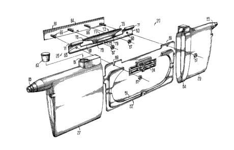
FIG. 1 is an exploded perspectil~e view of the closure of this
invention7
FIG. 2 is a plan view of a distribution arrangement in which
5 closures of this invention may be used;
FIG. 3 is a perspective view of one kind of cable with which the
closure of this invention may be used;
FIG. ~ is a perspective view which shows two cover portions of
the closure prior to assembly and end portions of cable such as that shown
10 in FIG. 3 extending through the cover portions;
FIG. 5 is an exploded perspective view of a bonding and gripping
assembly together with a splice tray prior to assembly with cable end
portions in position for splicing;
FIG. 6 is an enlarged side elevational view of the bonding and
15 gripping assembly after it has been assermbled and connected to end
portions of two cables to be spliced together;
FIG. 7 is a perspective view of the closure of FIG. 1 with two
optical fiber cables having end portions held between a clamp and a backing
plate of the bonding and gripping assembly and with portions of the f~lbers
20 disposed about a racetrack of the splice tray and connected together by
means of a splice; and
FIG. 8 is a perspective view of the closure of FIG. 1 after it has
been used to splice together two cable portions and after the cover portions
have been secured together.
~5 Detailed De~cription
Referring now to FIG. 1, there is shown an exploded perspective
view of a buried closure which is designated generally by the numeral 20.
The closure 20 includes a plastic splice tray 22, a splice holder 2~, a bonding
and gripping assembly designated generally by the numeral 26 and two
30 mating cover portions 27 and '~
Typically, a cable 30 (see l;`IG. ~) is used to connect a customer's
premises 3'1 to the network at a distribution closure 32. Should the cable
30 be severed or crushed, end portions 35-35 thereof must be spliced
together with the splice being protected in one of the closures 20-20.
- ~ -
The cable 30 includes a reinforced rlber unit 36 comprising an
optical fiber ~8, which includes a cc~atiIlg, and a plurality of rlbergrlass
strength members 41-41 arrayed there~bout. Typically, the optical ïïber 38
is buîfered and hence includes a layer of plastic such as polyvinyl chloride
5 (P~C~, for example, which encloses the coating of the optical fiber. The
strength members 41-41 and optical fiber 38 are enclosed by a plastic jacket
43. The reinforced fiber unit and a plurality of pairs oï insulated metallic
conductors 4~45 and a suitable waterblocking material 44 are enciosed in a
plastic core wrap 46, a corrugatecl metallic shiekl 47 having a longitudinal
10 seam and a plastic jacket 48.
The splice tray 22 ~see FIG. 5) may be molded from a rigi:1
plastic material such as polycarbonate, for example, and includes facilities
for holding a length of each of the optical ~lbers 38-38 from cables which are
to be spliced. Also, the splice tray 22 includes the splice holder 2~1 for
15 holding a plurality of splicing connectors (not shown). Preferably, the
splice holder is molded integrally with the tray 22 on one side thereof.
Typically, the tray 22 may accommodate as many as four splicing
connectors. Such a splicing connector may be that disclosed and claimed in
U.S. patent 4,545,644 or that disclosed and claimed in U.S. patent 4,691,98G.
20 In the alternative, the optical fibers may be spliced together by means of a
fusion splice. As can best be seen in FIG. 7, the splice tray "~ includes a
raceway 51 in which loops of the optical rlber or rlbers îrom the two cable
portions 35-35 to be spliced become disposed.
On the other side of the splice tray 2~ may be disposed end
25 portions of the copper conductors ~15-~15 of the cable portions 35-35 which
are to be spliced together. It is beneficial to maintain the copper
conductors separate and apart from the optical fiber connectors.
The bonding and gripping assernbly 26 includes a backing plate
61 (see FIG. 1) and a clamp 63. After it has been assembled and caused to
30 establish an electrical connection with the shield of each cable portion 35 to
be spliced together, electrical continuity is carried across the splice to a
remote ground point.
The backing plate 61 includes a plate 6~ and a plurality of
threaded posts 66-66 upstanding therefrom. Outer ones of the posts 66-6(3
35 are destined to be received in openings 68-68 of the clamp 63. Further, as
can be seen, the clamp 63 includes a center body portion 6~ and two ferrule
end portivns 71-71. Each of the ferrule elld portions 71-7l has an ac~llrate
configuration in transverse cross section which is adapted to conform
generally to the outside contour of any of a range of cable siz~s. Each
ferrule end portion 71 is adapted to become engaged with an unstripped end
5 portion of one of the cable portions 35-35 to be spliced together.
Between the ferrule end portions 71-71 of the clamp ~3 is
disposed a T-section 73 which is attached to the center body portion 69.
The T-shaped section 73 inciudes a post 75 and a cross-member 77. The
post 75 includes two holes 79-79 through which are adapted to be moved
10 the inner two of the threaded posts 66-66 of the plate 64. Each encl 78 of
the cross member 77 has a somewhat arcuately shaped transverse cross
section which is tapered in a longitudinal direction. As such, each free end
portion of the cross member 77 is adap'ed to be inserted into an end
portion of a cable portion 35 to be spliced to establish electrical engagement
15 with a shield of the cable.
The closure 20 also includes the pair of mating cover portions 27
and 29. Each of these has an oval shape in cross section transverse of the
axes of the cable end portions. Advantageously, the cover portions 27 and
29 are made of a plastic material which not only resists deterioration in a
20 buried environment but also which in the oval shaped configuration is
capable of resisting crushing loads of earth overhead when in a buried
environment. It should be observed from FIG. 1 that the cover portion ~7
includes a port 81 in which is disposed a plug 83. The port 81 is used to
allow introduction of an encapsulating material into the closure after the
25 cover portions have been assembled. Also, the cover portion ~9 includes a
collar 84 which is adapted to receive an end portion of the cover portion 27.
After the two cover portions 27 and 29 have been assernbled, provisions are
made for securing them together.
As mentioned hereinbefore, the closure 20 is adapted to enclose
30 the end portions of a range of cable sizes. In order to accommodate entry oi`any of a range of cable sizes, each cover portion 27 and ';>9 is provided with atapered entrance nozzle 85. Each nozzle 85 may be cut by an installer to
accommodate the outer diameter of the cable being spliced.
As was seen in FIG. 2, such a cable 30 is routed from a
35 distribution point to a customer's premises 34. It is buried and includes
suffilcient slack to facilitate splicing should it be required because of cable
damage. Generally, each of the cable portions 3.~35 to be spiiced includes a
corrugated metallic shield ~.7 which provides flexibility and strength for the
cable. Also, it dissipates electromagnetic radiation and provides lightning
and rodent protection. Of course, if two portions of such cable are to be
5 spliced together, electrical continuity ~rom the shield of one cable end
portion to the shield of the other end portion must be carried across the
splice.
For purposes of describing the method o~ using the closure 20, it
is assumed that the cable 30 which has been severed or crushed to
10 necessitate splicing of two portions 35-35 thereof includes at ieast one
optical ~lber which in a damaged cable would require splicing and at least
one pair of metallic conductors which also would require splicing.
In a nrst step of splicing two end portions of a cable 30 which
has been severed, the jacket 48 is slit for a predetermined distance along
15 each cable end portion and removed. The outer diameter of the cable 30 is
determined and the nozzle 85 of each cover portion 27 and 29 is cut to
accommodate that size. One end portion of one cable portion 35 is routed
through the nozzle 85 of one cover port;on 27 and other end portion of a
cable portion 35 is inserted through the nozzle of the other cover portion 29
20 (see FIG. 4). Then the corrugated shield 47 and core wrap 46 are removed
beginning at a point about 2.54 cm from the peripheral end of the outer
jacket 48, exposing the insulated metallic conductors 4S-45 and the optical
fiber or fibers.
Next, the copper conductors are moved aside, and the jacket 43
25 and the strength members 41-41 removed to expose the rlber or rlbers. The
lengths of the exposed optical fibers 38-38 and metallic conductors 45-45 are
exaggerated in FIG. 4. The strength members 41-41 are cut and the
buffered fiber is wiped clean. The clamp 63 and the backing plate 61 are
preassembled (see FIG. 5) by causing each of the threaded posts 66-66 to
30 become aligned with and extend through aligned openings 68-68 and 79-~9
in the clamp. Nuts 87-87 are turned partially into the posts 66-66 after
which a cable end portion 35 is moved to cause the corrugated shield 47
thereof to be moved in a longitudinal direction between the clamp 63 and
the backing plate 61. This causes an end portion 78 of the clamp 63 to be
35 moved between the shield 47 and adjacent portions of the cable portion 35
(see FIG. 6). The longitudinal motion is discontinued when the corrugated
- 7 -
shield ~17 is adjacent to the second threaded post from the adjacent free end
of the backing plate ~1. At that time, the nut 87 on the second post is
tightened. This procedure is repeated for the other cable end portion 3.5.
Afterwards, the splice tray 22 is inserted into the opening between the
5 cables to cause slots 8~3-89 thereof to be moved over the two outer~ost posts
6G-66 (see FIG. 1). The nuts 87-87 previously partially turned onto the
outermost posts 61i-66 are tightened to secure the splice tray 22 to the
bonding and gripping assembly 26 and grip the cable end portions 35-:3.5
between the ciamp 63 and the backing plate 61. Also, this causes an
10 electrical connection between the cable shields ~7-~7 and the backing plate
61 to be established.
The metallic conductor pairs 4~45 are spliced and secured to the
backside of the splice tray as seen in FIG. 7 with a small cable tie ~5. Any
of of a number of numerous commercially available splice connectors such as
that disclosed in U.S. patent 3,772,635, for example, may be usecl to splice
the metallic conductors. Then the buffered optical fibers 38-38 ~re routed
along the raceway 51 (see again FIG. 7) and spliced, for exa~ple, with the
priorly mentioned rotary splice connector. An elastic band 90 is wrapped
about the tray to hold th optical l~lbers 38-38 in place.
In a ~lnal sequence of steps, the two cover portions 27 and "~ are
moved toward each other to cause the end portion of the portion 27 to be
received in the collar 84 of the portion 29 (see FIG. 8). A convolution or
convolutions of a vinyl tape ~1 are wrapped about the joint between the
cover portions 27 and 2~ and about the exit points of the end portions of
the cables from the no~zles 85-85. A cable tie 93 is placed about the co~er
portions to secure them together. The plug 83 is removed from the port 81
of the one cover portion 27 and a suitable encapsulant is introduced
through the port into the closure. Then the plug 83 is reinserted into the
port 81.
It should be mentioned that in the closure ~0, the encapsulant is
introduced directly into engagement with the splice. This is unlike closures
of the prior art in which the splice point is enclosed separately within the
closure so that the encapsulant may not reach the splice point. It has been
found that direct contact of the encapsulant with the splice point does not
35 affect adversely the transmission performance of the flbers on the electricalconductors, and, of course, enhances the protection of the splice points from
~q~
moisture .
The closure of this invention h~s been disclosed ~ ith respect to
splicing a composite optical ~Iber-metallic conductor cable. It should be
understood that the closure may be used to enclose a splice between
5 portions of an all ~Iber cable or of an all metallic conductor cable.
It is to be understood that the above-described arrangements are
simply illustrative of the invention. Other arrangements may be devised by
those skilled in the art which will embody the principles of the invention
and fall within the spirit and scope thereof.