Note: Descriptions are shown in the official language in which they were submitted.
1 307676
BUILDING STRUCTURE AND METHOD
AND ELEMENT FOR MAKING SAME
The present invention relates to a buildiny structure,
comprising a first plate and means attached thereto forming
parallel channels, of which at least some are filled with
concrete forming ribs.
Floors and walls - and particularly wooden floors -
often have such a low stiffness that they vibrate under
dynamic loads. Several attempts have been made to reinforce
and stiffen such floors but without technically and
economically satisfactory results.
It is known to use corrugated steel plates as bottom in
forms for pouring concrete floors. The upwardly concave
portions of these plates become filled with concrete during
the pouring and therefore form stiffening ribs depending on
the bottom side of the floor, while the steel plate itself
becomes an integral part for the concrete floor and forms a
reinforcement thereof.
It will be understood that such corrugated steel plates
have relatively low stiffness, particularly transversally of
the longitudinal direction of the corrugations, a fact
requiriny particular considerations regarding both support
and loading, e.g. traffic b~ persons and equipment, before
the concrete is poured. The concrete will fil] all upwardly
open corrugations so that the concrete-filled ribs usually
will be placed relatively close to each other and the floor
will be correspondingly heavy. Furthermore, the center of
gravity of the corruga~ed plate will be situated midway
between the top and bottom of the corrugations, which leads
to the fact that the reinforcement constituted by the steel
in the plate will not have the optimum position near the
bottom of the ribs. Since the corrugated plate forms an
integral part of the concrete floor, it will not have
appreciable sound dampening properties.
In order to alleviate some of these drawbacks, one has
provided the corrugated plate with a plane steel plate on
2 1 ~07676
the bottom side. Such a plate is known e.g. from US-PS No.
4 630 414, Fig. 3. However, neither this plate does not
solve the above-mentioned problems in a satisfactory
manner, and it is relatively expensive.
One of the objects of the present invention is thus to
provide a building structure of said type, which to a large
extent avoids the drawbacks and deficiencies mentioned
above.
According to the invention this is obtained by the
building structure comprising a second plate which is
parallel to the first plate and also is attached to the
channel forming means, the plates being substantially
continuous and the ribs being provided with reinforcements
in any portion subjected to high tensile loads.
By employing two plates being substantially continuous
one is able to obtain a relatively stiff structure even with
the use of inexpensive materials. The two plates also
ascertain that the channels are covered on both sid~s, thus
providing control with the channels to be filled with
concrete. This permits limiting the number of stiffening
and reinforcing ribs to the extent necessary for the use at
hand, thus saving both weight and cost. Such light
structures may be used e.g. in roofs and walls.
If the building structure is to be used as flooring, it
is su~gested according to the invention that the second of
the two plates be provided with a cover of concrete, the
concrete in the cover and in the ribs being in communication
with each other through holes taken out in the second plate
so that a monolithic connection is formed between the ribs
and the cover. Also in this case one has full control with
the number of channels which are filled with concrete for
the formation of ribs. This entails that the distance
between the plate and the heigth of the ribs may be made
relatively large, so that the effect of the ribs becomes
correspondingly larger and the necessary number of ribs
becomes correspondingly smaller. In the event that the
channels are formed by a corruyated element between the
plates, it will not be necessary to pour concrete in more
3 1 307676
than one third of the channels even in strongly loaded
floors.
One has found that a building structure according to
the invention gives surprisingly low sound transmission
numbers. One is not certain why this is so, but assumes
that some o~ the explanation may be that the concrete part
on the one side and the opposite plate with the empty
channels on the other side, form two structures with very
different natural frequencies.
According to the invention it is also provided a method
for making a building structure of the above-mentioned type.
This method is characterized by prefabricating an element
essentially being comprised by two parallel plates attached
to means in between forming channels, holes being taken out
in one of the plates with a predetermined spacing along some
of the channels, and reinforcements being placed in these
channels, which then are filled with concrete.
By such a method the elements may be prefabricated in a
factory without regard to their later use because one does
not have to determine the number of channels to be filled
with concrete and the holes to be taken out for this purpose
before the element has arrived at the building site or has
been placed in its final location in the building of which
it forms a part. This of course simplifies production,
storage and handling o~ the elements, with resulting cost
savings.
If the prefabricated element is to be provided with a
concrete cover, it is advantageous in accordance with the
method of the invention that the concrete be poured in the
respective channels concurrently with pouring the cover.
This ensures a good connection between the cover and the
concrete ribs formed in the channels. If the araa repre-
sented by the holes in the plate facing the cover should
not be sufficient to provide the necessary shearing force
transmission in particular uses, it is suggested according
to the invention to arrange shearing force reinforcement in
the holes before pouring the concrete.
The invention further relates to an element for
4 1 307676
performing the above method. This element is characterized
in that it comprises two parallel plates, which are attached
to means in between forming channels, in that the plates are
made of materials chosen from the group comprising gypsum,
fiber composits, wood or cement-based materials, preferably
gympsum boards, and in that the channel forming means are
made of materials chosen from the group comprising wood,
cardboard, plastic or metal, preferably corrugated card-
board.
In order to simplify making the holes in one of the
plates and to ensure that the holes are not located in
places where they may damage the channels or weaken the
element to a harmful degree, it is suggested according to
the invention to provide the plate in question with
weakenings or markings for forming the holes with a
predetermined spacing along at least some of the channels.
Furthermore, it is suggested according to the invention
to provide the element with elements of wood along at least
two of its edges. This will reinforce the edges and make it
easier to transport and handle the element without subjec-
ting it to damage.
In order for the better understanding of the invention
it will be described more closely with reference to the
exemplifying embodiments shown in the appended drawings.
Fig. 1 shows isometrically a portion of an element
according to the invention.
Fig. 2 shows a section through the element in Fig. 1
after providing it with a cover of concrete.
Fig. 3 shows an alternative embodiment in section
similar to Fig. 2.
In the various figures like parts are given the same
reference numerals.
It is first referred to Fig. 1, which sh~ws a corner
section of a prefabricated element generally designated 1.
The eIement comprises two parallel plates 2, 3, e.g. gypsum
boards, which are held spaced apart by means of a channel
forming element 4 in the form of a folded plate of corru-
gated cardboard. The plate 4 forms upwards and downwards
1 307676
facing ridges which are glued to a respective one of the
plates 3 and 2, so that these together form a rigid element.
The folded plate ~ further forms a number of upwards and
downwards facing channels 5 and 6, respectively, which are
closed by the plates 3 and 2, respectively. At their outer
longitudinal edge the plates 2, 3 are provided with an
element 7 of wood, which reinforces the edge section and
also forms distance means~
The plate 3 is provided with circular hole markings 8
placed with equal spacing opposite the channels 5.
Correspondlng markings may be arranged in the plate 2
opposite the channels 6. When using the element 1 one can
choose which of the plates 2, 3 is to face upwards,
depending on how near the edge element 7 one wishes the
firs~ channel filled with concrete.
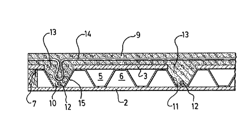
Fig. 2 shows a section through the element 1 after it
has been provided with a concrete cover 9 and two of the
channels 5 have been filled with concrete so as to form
ribs 10, 11. These ribs are provided with steel reinforment
12 near the bottom.
Pouring concrete into the ribs lO, 11 has taken place
after holes 13 have been made in the plate 3 of the element
1 where markings 8 are shown in Fig. 1. The cover 9 is
provided with a secondary reinforcement 14. In case the
shearing forces to be transmitted between the cover and rib
are large, a shearing force reinforcement 15 is placed into
the ri~ through the hole 13, as shown for the rib 10. Here
the shearing rorce reinforcement 15 is shown as a bent down
portion of the secondary reinforcement 14, but the shearing
force reinforcement may of course take any other suitable
form.
In Fig. 3 one of many possible alternative embodiments
of the building structure according to the invention is
shown~ Here, the channels to be filled with concrete are
formed by elongate, boxlike elements made from e.g. sheet
metal or plastic. These channel elements are glued or
attached by mechanical means to the plates 2, 3. The
channels may also be envisioned to take other forms. For
6 1 307676
example they may be limited sideways by parallel wooden
battens, or by means of generally U-shaped sheet metal
sections placed edgeways with the flanges facing away from
each other. If the channel limiting means do not withstand
moisture, the channels may be clad internall~ with a
suitable foil.
Fig. 3 also shows how the spaces delimited by the
plates 2, 3 and channels may be filled with insulating
material 17. Likewise, pipes 18 are shown for electric
power or water. Corresponding pipes may also be placed in
the cover 9. Pipes extending transversally of the channels,
as indicated by 19, may also be used if they are brought in
place during the manufacture of the element 1. These pipes
should preferably be placed between the hole markings 8.
It will be understood that the invention is not limited
to the exemplifying embodiments shown, but may be varied and
modified in a number of ways, both with regard to design and
use. Thus, the element 1 may find use without concrete in
the channels, such as in lightly loaded structures like
ceilings and light walls. In other words, it is not
necessary to utilize the elements in a horizontal position.
By standing the elements on edge ~with the channels
vertical) the element may be used in supporting walls if the
necessary number of channels are filled with concrete. In
ex~ernal walls or foundation walls, the concrete may
afterwards be applied on the outside. When using the
elements iJI sloping roofs, wherein some of the channels are
filled with concrete, attachment means for laths and battens
may advantageously be cast into the ribs through the holes
in the upper pla~e of the element.
It will also be understood that the building structure
according to the invention may he insulated in a large
number of ways. Not only may the insulating material be
placed in the channels of the element, as shown in Fig. 3,
but the insulation may also be placed between the upper
plate and the concrete cover or on th~ bottom side of the
element. Furthermore, the channels to be filled with
concrete may first be lined entirely or in part with
7 1 3~767~
insulating material. Particularly in embodiments where the
empty channels are filled with insulating material, it may
be suitable to line the bottom with insulating material in
those channels which are to be filled with concrete.
~ he element according to the invention may also
advantageously be made with ribs in two or more directions
by forming the channel forming means as a grating of
channels and/or cells. In this manner the stiffness of the
element may by increased in several directions.
The choice of material for the plates of the element
may be adapted to the use of the element. Gypsum-boards
have proven suitable in many connections, but also other
materials li~e particle boards or composits of gypsum and
chips may in many cases be useful. In elements where one of
the plates is to form an outer ~all or foundation wall, this
plate may advantageously be a concrete plate, while the
inner plate may for instance consist of gypsum or particle
board. Thus, it is not necessary to use the same material
in both plates of the element~ If the element entirely or
partly is made of materials which do not withstand rain or
moisture for a shorter or longer period, be it during
transport, storage or installation, a waterproof layer, for
instance a plastic ~oil may be arranged on the upper side of
the element. Such a foil need not be removed before pouring
a concrete cover, except for the holes which must be made
before pouring the concrete.