Language selection

Search

Patent 1307726 Summary

Third-party information liability

Some of the information on this Web page has been provided by external sources. The Government of Canada is not responsible for the accuracy, reliability or currency of the information supplied by external sources. Users wishing to rely upon this information should consult directly with the source of the information. Content provided by external sources is not subject to official languages, privacy and accessibility requirements.

Claims and Abstract availability

Any discrepancies in the text and image of the Claims and Abstract are due to differing posting times. Text of the Claims and Abstract are posted:

  • At the time the application is open to public inspection;
  • At the time of issue of the patent (grant).
(12) Patent: (11) CA 1307726
(21) Application Number: 596335
(54) English Title: SIGNAL DEVICE FOR PNEUMATIC TIRE
(54) French Title: DISPOSITIF AVERTISSEUR POUR PNEUMATIQUE
Status: Deemed expired
Bibliographic Data
(52) Canadian Patent Classification (CPC):
  • 116/1
  • 152/189
(51) International Patent Classification (IPC):
  • B60C 23/04 (2006.01)
  • B60C 23/00 (2006.01)
(72) Inventors :
  • WANG, HSUG-FANG (China)
(73) Owners :
  • WANG, HSUG-FANG (China)
(71) Applicants :
(74) Agent: OYEN WIGGS GREEN & MUTALA LLP
(74) Associate agent:
(45) Issued: 1992-09-22
(22) Filed Date: 1989-04-11
Availability of licence: N/A
(25) Language of filing: English

Patent Cooperation Treaty (PCT): No

(30) Application Priority Data:
Application No. Country/Territory Date
8814606.3 United Kingdom 1988-06-20

Abstracts

English Abstract


ABSTRACT OF THE DISCLOSURE
The invention provides a combined cap and signal
device to be attached to a tire after the tire is
inflated. The device includes an electric alarming
unit mounted in a cap-like casing which incorporates an
adaptor to be threadedly connected to an inflating
valve of the tire. A resilient disc is disposed in
the adaptor to be forced by air so that the disc causes
the circuit of the electric alarming unit to be opened
when the tire is not deflated.


Claims

Note: Claims are shown in the official language in which they were submitted.


THE EMBODIMENTS OF THE INVENTION IN WHICH AN EXCLUSIVE
PROPERTY OR PRIVILEGE IS CLAIMED ARE DEFINED AS FOLLOWS


1. A combined cap and signal device for a pneumatic tire
comprising:
a cap-like casing having a closed end and an open
threaded end
a hollow adaptor having a first threaded end
engaging with said open threaded end of said casing and
a second threaded end to be connected to an inflating
valve of the tire, said hollow adaptor having a wall
which has a stepped portion defining an annular
shoulder and an internal thread formation adjacent to
said annular shoulder, said hollow adaptor further
having a transverse partition member formed near said
second threaded end, said transverse partition member
having a central finger piece axially projecting
therefrom to open the inflating valve of the tire and
air inlet openings,
a disc member made of a resilient material and
having a peripheral flange secured to said annular
shoulder, said disc member cooperating with said
partition member to confine an air chamber
communicating with said air inlet openings, said disc
member having a projection axially extending in a
direction opposite to said finger piece;
a hollow screw member for securing said peripheral
flange of said disc member to said annular shoulder,
said hollow screw member being inserted in said adaptor


to clamp said peripheral flange of said disc member
against said annular shoulder and having an external
thread engaging with said internal thread formation of
said hollow adaptor, said hollow screw member having an
annular end serving as an electrical contact surface;
an electric alarming unit mounted in said cap-like
casing, said alarming unit including a sound producing
circuit, and a cell means electrically connected to
said sound producing circuit,
first means for electrically connecting said sound
producing circuit to said electrical contact surface of
said hollow screw member;
second means for electrically connecting said cell
means to said electrical contact surface of said hollow
screw member, said means including a conductive plate
member to contact said electrical contact surface, and
a coil spring having one end connected to said
conductive plate member and the other end electrically
connected to said cell means;
said projection of said disc member pushing said
conductive plate to move away from said hollow screw
member when the tire is not deflated, said spring
urging said conductive plate to be in contact with said
hollow screw member when the tire is deflated to a
predetermined reduced pressure.
2. A combined cap and signal device as claimed in Claim
1, wherein said cap-like casing and said hollow adaptor
are made of an insulating material.

Description

Note: Descriptions are shown in the official language in which they were submitted.


1307~2f~;


SIGNAL DEVICE FOR PNEUMATIC TIRE
BACKGROUND OF THE INVENTION
This invention relates to a signal device for a
pneumatic tire and particularly to a signalling cap for
the inflating valve of a pneumatic tire which has an
electrical sound producing unit for the purpose of
alarming when the tire is deflated to a pressure below
a predetermined proper pressure.
Signal devices for pneumatic tires are known in
the art. Some of them are of the type which is used
during inflation of the tire for the purpose of
10 alarming when the pressure in the tire exceeds a
predetermined required pressure. Some of them are used
as a cap for the inflating valve of a tire as well as
a signal device to signal when the pressure in the tire
is seriously deflated. U.S. Patent No. 2,334,095
15 discloses a signal device of the latter type which
includes a cap-like casing in which is mounted a valve
that permit air to enter the casing from the tire to
which the casing is connected when the tire is deflated
to a predetermined pressure. The casing also contains
20 a sound making unit which has an air-tight hood member
that explodes when air enters the casing. U.S.
Patent No. 1,626,294 discloses a signal device
which is mounted on the inflating valve of a tire
after the tire is inflated and which includes a spring
25 loaded thimble to be used as an indicator to show the
deflated pressure in the tire.
~k

130'77Z6


SUMMARY OF THE INVENTION
An object of the invention is to provide an
improved combined cap and signal device which includes
an electric sound producing unit which will alarm when
5 the tire to which the device is attached is seriously
deflated.
Another object of the invention is to provide a
combined cap and signal device which has a simpler
construction for actuating a sound producing unit than
10 the other similar conventional signal devices.
- The invention provides a combined cap and signal
device which comprises a cap-like casing and a hollow
adaptor threadedly coupled together. The hollow
adaptor has a stepped portion defining an annular
15 shoulder and an internal thread formation adjacent to
the annular shoulder. A transverse partition member is
formed in the adaptor and having a central finger piece
axially projecting therefrom to open the inflating
valve of the tire and air inlet openings.
A disc member which is made of a resilient
material is secured to the annular shoulder with its
annular flange. The disc member cooperates with the
partition member to confine an air chamber
communicated with the air inlet openings of the
25 partition member. The disc member has a projection
axially extending in a direction opposite to the finger
piece. A conductive hollow screw member is inserted in


1307~726


the adaptor to clamp the peripheral flange of the disc
member against the annular shoulder. The screw member
has an external thread engaged with the internal
thread of the adaptor.
An electric alarming unit is mounted in the cap-
like casing and has a cell means which is in contact
with a coil spring which in turn is connected to a
conductive plate to urge the conductive plate to
contact said conductive hollow screw. The projection
10 of the disc member pushes the conductive plate to move
away from the hollow screw member when the tire is not
deflated. The spring urges the conductive plate to be
in contact with the hollow screw member when the tire
is deflated to a predetermined reduced pressure.
The exemplary preferred embodiment will be
described in detail with reference to the accompanying
drawings, in which:
BRIEF DESCRIPTION OF THE DRAWINGS
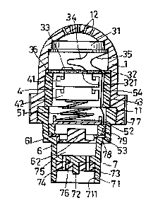
Figures 1 and 2 are sectional view of a combined
20 cap and signal device according to the present
invention; and
Figure 3 is a circuit diagram of the electric
alarming means of the device.
DETAILED DESCRIPTION OF THE PREFERRED EMBODIMENT
Referring to the drawings, a signal device
according to the present invention is shown, having a
cap-like casing 1 and a hollow adaptor 7 which are
made of an electric insulating material and which are

1307726


threadedly coupled together. The cap-like casing 1 has
a round closed end and an open end with an internal
thread 11. The hollow adaptor 7 has an open end 71
which has an internal thread 711 to be connected
threadedly to an inflating valve of a tire. Another
open end of the hollow adaptor 7 has an external thread
77 which engages the thread 11 of the cap-like casing
1. Adjacent to the open end 71 of the hollow adaptor 2
is a transverse partition plate 76 which has a central
10 axially extending finger piece 72 to push the
-inflating valve of the tire to an open position when
the adaptor 2 is mounted on the inflating valve. The
partition plate 76 is further provided with air inlet
openings 74. A gasket 73 is press fitted in the adaptor
15 member and abuts with the partition plate 76. The
wall of the hollow adaptor member 7 is stepped to form
an annular shoulder 78 and has an internal thread 79.
In the hollow adaptor 7 is a disc member 6 which
is made of a rubber material and has a peripheral
20 flange 61 clamped by a hollow screw member 53 against
the annular shoulder 78. The hollow screw member 53
is made of a conductive metal and engages with the
internal thread 79 of the adaptor member 7, thereby
firmly holding the disc member 6 in the adaptor 7. The
25 disc member 6 further has a projection 62 extending
axially therefrom in a direction opposite to the finger
piece 72 of the partition member 76. The disc member 6


1307726


and the partition member 78 cooperate to confine an air
chamber 75 which will be communicated with the interior
of the tire through the inflating valve of the tire and
air inlet openings 74.
An electric alarming unit is disposed
adjacent to the closed end of the cap-like casing 1. It
includes a buzzer 31 and a substantially circular
printed circuit board 32 bearing a sound producing
integrated circuit 33. The buzzer 31 includes a casing
10 which is seated against shoulder formations 13 and 14
which are formed at the inner side of the cap-like
casing 1. The printed circuit board 32 is seated on an
an~ular shoulder 36 and is clamped thereat by a sleeve
43 which is made of an insulating material and which is
15 inserted into the casing 1. The sleeve 43 and the
board 32 confines a chamber for accommodating
batteries 42. The closed end of the casing 1 is
provided with openings 12 for the outlet of sound.
Conductors 34 and 35 are provided to electrically
20 interconnect the integrated circuit 33 and the
buzzer 31.
The printed circuit board 32 further has a
terminal 321 to be in contact with a positively charged
terminal of the battery. A conductive coil spring 51
25 is provided to be in contact with a negatively charged
terminal of the battery. The coil spring 51 is
connected to a conductive plate 52 to urge the
plate to contact the end of the hollow screw member 53.

1307726


The hollow screw member 53 is in turn connected to
another terminal of the printed circut board 32.
When the signal device of the present invention is
attached to the inflating valve of an inflated tire,
5 the valve of the tire is opened by the finger piece 72
and the disc member 6 is pushed upward as is shown in
Figure 2. The projection 62 of the disc member 6
pushes the conductive plate 52 against the force of the
spring 51 and thereby separates the conductive plate
10 52 and the hollow screw member 53, placing the alarming
unit in an OFF position. When the tire is deflated to
a predetermined reduced pressure, the conductive plate
51 is pushed by the spring 51 to be in contact with the
hollow screw member 53. In this situation, the sound
15 producing circuit 33 produces an alarming sound.
With the invention thus explained, it is apparent
that numerous modifications and variations can be made
without departing from the scope of the invention. It
is therefore intended that the invention be limited as
20 indicated in the appended claims.

Representative Drawing
A single figure which represents the drawing illustrating the invention.
Administrative Status

For a clearer understanding of the status of the application/patent presented on this page, the site Disclaimer , as well as the definitions for Patent , Administrative Status , Maintenance Fee  and Payment History  should be consulted.

Administrative Status

Title Date
Forecasted Issue Date 1992-09-22
(22) Filed 1989-04-11
(45) Issued 1992-09-22
Deemed Expired 1997-09-22

Abandonment History

There is no abandonment history.

Payment History

Fee Type Anniversary Year Due Date Amount Paid Paid Date
Application Fee $0.00 1989-04-11
Maintenance Fee - Patent - Old Act 2 1994-09-22 $50.00 1994-04-19
Maintenance Fee - Patent - Old Act 3 1995-09-22 $50.00 1995-07-25
Owners on Record

Note: Records showing the ownership history in alphabetical order.

Current Owners on Record
WANG, HSUG-FANG
Past Owners on Record
None
Past Owners that do not appear in the "Owners on Record" listing will appear in other documentation within the application.
Documents

To view selected files, please enter reCAPTCHA code :


To view images, click a link in the Document Description column. To download the documents, select one or more checkboxes in the first column and then click the "Download Selected in PDF format (Zip Archive)" or the "Download Selected as Single PDF" button.

List of published and non-published patent-specific documents on the CPD .

If you have any difficulty accessing content, you can call the Client Service Centre at 1-866-997-1936 or send them an e-mail at CIPO Client Service Centre.


Document
Description 
Date
(yyyy-mm-dd) 
Number of pages   Size of Image (KB) 
Drawings 1993-11-04 1 31
Claims 1993-11-04 2 65
Abstract 1993-11-04 1 12
Cover Page 1993-11-04 1 11
Description 1993-11-04 6 180
Representative Drawing 2001-12-04 1 13
Fees 1995-07-25 1 49
Fees 1994-08-19 1 45