Sélection de la langue

Search

Sommaire du brevet 1307726 

Énoncé de désistement de responsabilité concernant l'information provenant de tiers

Une partie des informations de ce site Web a été fournie par des sources externes. Le gouvernement du Canada n'assume aucune responsabilité concernant la précision, l'actualité ou la fiabilité des informations fournies par les sources externes. Les utilisateurs qui désirent employer cette information devraient consulter directement la source des informations. Le contenu fourni par les sources externes n'est pas assujetti aux exigences sur les langues officielles, la protection des renseignements personnels et l'accessibilité.

Disponibilité de l'Abrégé et des Revendications

L'apparition de différences dans le texte et l'image des Revendications et de l'Abrégé dépend du moment auquel le document est publié. Les textes des Revendications et de l'Abrégé sont affichés :

  • lorsque la demande peut être examinée par le public;
  • lorsque le brevet est émis (délivrance).
(12) Brevet: (11) CA 1307726
(21) Numéro de la demande: 596335
(54) Titre français: DISPOSITIF AVERTISSEUR POUR PNEUMATIQUE
(54) Titre anglais: SIGNAL DEVICE FOR PNEUMATIC TIRE
Statut: Réputé périmé
Données bibliographiques
(52) Classification canadienne des brevets (CCB):
  • 116/1
  • 152/189
(51) Classification internationale des brevets (CIB):
  • B60C 23/04 (2006.01)
  • B60C 23/00 (2006.01)
(72) Inventeurs :
  • WANG, HSUG-FANG (Chine)
(73) Titulaires :
  • WANG, HSUG-FANG (Chine)
(71) Demandeurs :
(74) Agent: OYEN WIGGS GREEN & MUTALA LLP
(74) Co-agent:
(45) Délivré: 1992-09-22
(22) Date de dépôt: 1989-04-11
Licence disponible: S.O.
(25) Langue des documents déposés: Anglais

Traité de coopération en matière de brevets (PCT): Non

(30) Données de priorité de la demande:
Numéro de la demande Pays / territoire Date
8814606.3 Royaume-Uni 1988-06-20

Abrégés

Abrégé anglais


ABSTRACT OF THE DISCLOSURE
The invention provides a combined cap and signal
device to be attached to a tire after the tire is
inflated. The device includes an electric alarming
unit mounted in a cap-like casing which incorporates an
adaptor to be threadedly connected to an inflating
valve of the tire. A resilient disc is disposed in
the adaptor to be forced by air so that the disc causes
the circuit of the electric alarming unit to be opened
when the tire is not deflated.

Revendications

Note : Les revendications sont présentées dans la langue officielle dans laquelle elles ont été soumises.


THE EMBODIMENTS OF THE INVENTION IN WHICH AN EXCLUSIVE
PROPERTY OR PRIVILEGE IS CLAIMED ARE DEFINED AS FOLLOWS


1. A combined cap and signal device for a pneumatic tire
comprising:
a cap-like casing having a closed end and an open
threaded end
a hollow adaptor having a first threaded end
engaging with said open threaded end of said casing and
a second threaded end to be connected to an inflating
valve of the tire, said hollow adaptor having a wall
which has a stepped portion defining an annular
shoulder and an internal thread formation adjacent to
said annular shoulder, said hollow adaptor further
having a transverse partition member formed near said
second threaded end, said transverse partition member
having a central finger piece axially projecting
therefrom to open the inflating valve of the tire and
air inlet openings,
a disc member made of a resilient material and
having a peripheral flange secured to said annular
shoulder, said disc member cooperating with said
partition member to confine an air chamber
communicating with said air inlet openings, said disc
member having a projection axially extending in a
direction opposite to said finger piece;
a hollow screw member for securing said peripheral
flange of said disc member to said annular shoulder,
said hollow screw member being inserted in said adaptor


to clamp said peripheral flange of said disc member
against said annular shoulder and having an external
thread engaging with said internal thread formation of
said hollow adaptor, said hollow screw member having an
annular end serving as an electrical contact surface;
an electric alarming unit mounted in said cap-like
casing, said alarming unit including a sound producing
circuit, and a cell means electrically connected to
said sound producing circuit,
first means for electrically connecting said sound
producing circuit to said electrical contact surface of
said hollow screw member;
second means for electrically connecting said cell
means to said electrical contact surface of said hollow
screw member, said means including a conductive plate
member to contact said electrical contact surface, and
a coil spring having one end connected to said
conductive plate member and the other end electrically
connected to said cell means;
said projection of said disc member pushing said
conductive plate to move away from said hollow screw
member when the tire is not deflated, said spring
urging said conductive plate to be in contact with said
hollow screw member when the tire is deflated to a
predetermined reduced pressure.
2. A combined cap and signal device as claimed in Claim
1, wherein said cap-like casing and said hollow adaptor
are made of an insulating material.

Description

Note : Les descriptions sont présentées dans la langue officielle dans laquelle elles ont été soumises.

1307~2f~;


SIGNAL DEVICE FOR PNEUMATIC TIRE
BACKGROUND OF THE INVENTION
This invention relates to a signal device for a
pneumatic tire and particularly to a signalling cap for
the inflating valve of a pneumatic tire which has an
electrical sound producing unit for the purpose of
alarming when the tire is deflated to a pressure below
a predetermined proper pressure.
Signal devices for pneumatic tires are known in
the art. Some of them are of the type which is used
during inflation of the tire for the purpose of
10 alarming when the pressure in the tire exceeds a
predetermined required pressure. Some of them are used
as a cap for the inflating valve of a tire as well as
a signal device to signal when the pressure in the tire
is seriously deflated. U.S. Patent No. 2,334,095
15 discloses a signal device of the latter type which
includes a cap-like casing in which is mounted a valve
that permit air to enter the casing from the tire to
which the casing is connected when the tire is deflated
to a predetermined pressure. The casing also contains
20 a sound making unit which has an air-tight hood member
that explodes when air enters the casing. U.S.
Patent No. 1,626,294 discloses a signal device
which is mounted on the inflating valve of a tire
after the tire is inflated and which includes a spring
25 loaded thimble to be used as an indicator to show the
deflated pressure in the tire.
~k

130'77Z6


SUMMARY OF THE INVENTION
An object of the invention is to provide an
improved combined cap and signal device which includes
an electric sound producing unit which will alarm when
5 the tire to which the device is attached is seriously
deflated.
Another object of the invention is to provide a
combined cap and signal device which has a simpler
construction for actuating a sound producing unit than
10 the other similar conventional signal devices.
- The invention provides a combined cap and signal
device which comprises a cap-like casing and a hollow
adaptor threadedly coupled together. The hollow
adaptor has a stepped portion defining an annular
15 shoulder and an internal thread formation adjacent to
the annular shoulder. A transverse partition member is
formed in the adaptor and having a central finger piece
axially projecting therefrom to open the inflating
valve of the tire and air inlet openings.
A disc member which is made of a resilient
material is secured to the annular shoulder with its
annular flange. The disc member cooperates with the
partition member to confine an air chamber
communicated with the air inlet openings of the
25 partition member. The disc member has a projection
axially extending in a direction opposite to the finger
piece. A conductive hollow screw member is inserted in


1307~726


the adaptor to clamp the peripheral flange of the disc
member against the annular shoulder. The screw member
has an external thread engaged with the internal
thread of the adaptor.
An electric alarming unit is mounted in the cap-
like casing and has a cell means which is in contact
with a coil spring which in turn is connected to a
conductive plate to urge the conductive plate to
contact said conductive hollow screw. The projection
10 of the disc member pushes the conductive plate to move
away from the hollow screw member when the tire is not
deflated. The spring urges the conductive plate to be
in contact with the hollow screw member when the tire
is deflated to a predetermined reduced pressure.
The exemplary preferred embodiment will be
described in detail with reference to the accompanying
drawings, in which:
BRIEF DESCRIPTION OF THE DRAWINGS
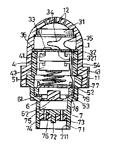
Figures 1 and 2 are sectional view of a combined
20 cap and signal device according to the present
invention; and
Figure 3 is a circuit diagram of the electric
alarming means of the device.
DETAILED DESCRIPTION OF THE PREFERRED EMBODIMENT
Referring to the drawings, a signal device
according to the present invention is shown, having a
cap-like casing 1 and a hollow adaptor 7 which are
made of an electric insulating material and which are

1307726


threadedly coupled together. The cap-like casing 1 has
a round closed end and an open end with an internal
thread 11. The hollow adaptor 7 has an open end 71
which has an internal thread 711 to be connected
threadedly to an inflating valve of a tire. Another
open end of the hollow adaptor 7 has an external thread
77 which engages the thread 11 of the cap-like casing
1. Adjacent to the open end 71 of the hollow adaptor 2
is a transverse partition plate 76 which has a central
10 axially extending finger piece 72 to push the
-inflating valve of the tire to an open position when
the adaptor 2 is mounted on the inflating valve. The
partition plate 76 is further provided with air inlet
openings 74. A gasket 73 is press fitted in the adaptor
15 member and abuts with the partition plate 76. The
wall of the hollow adaptor member 7 is stepped to form
an annular shoulder 78 and has an internal thread 79.
In the hollow adaptor 7 is a disc member 6 which
is made of a rubber material and has a peripheral
20 flange 61 clamped by a hollow screw member 53 against
the annular shoulder 78. The hollow screw member 53
is made of a conductive metal and engages with the
internal thread 79 of the adaptor member 7, thereby
firmly holding the disc member 6 in the adaptor 7. The
25 disc member 6 further has a projection 62 extending
axially therefrom in a direction opposite to the finger
piece 72 of the partition member 76. The disc member 6


1307726


and the partition member 78 cooperate to confine an air
chamber 75 which will be communicated with the interior
of the tire through the inflating valve of the tire and
air inlet openings 74.
An electric alarming unit is disposed
adjacent to the closed end of the cap-like casing 1. It
includes a buzzer 31 and a substantially circular
printed circuit board 32 bearing a sound producing
integrated circuit 33. The buzzer 31 includes a casing
10 which is seated against shoulder formations 13 and 14
which are formed at the inner side of the cap-like
casing 1. The printed circuit board 32 is seated on an
an~ular shoulder 36 and is clamped thereat by a sleeve
43 which is made of an insulating material and which is
15 inserted into the casing 1. The sleeve 43 and the
board 32 confines a chamber for accommodating
batteries 42. The closed end of the casing 1 is
provided with openings 12 for the outlet of sound.
Conductors 34 and 35 are provided to electrically
20 interconnect the integrated circuit 33 and the
buzzer 31.
The printed circuit board 32 further has a
terminal 321 to be in contact with a positively charged
terminal of the battery. A conductive coil spring 51
25 is provided to be in contact with a negatively charged
terminal of the battery. The coil spring 51 is
connected to a conductive plate 52 to urge the
plate to contact the end of the hollow screw member 53.

1307726


The hollow screw member 53 is in turn connected to
another terminal of the printed circut board 32.
When the signal device of the present invention is
attached to the inflating valve of an inflated tire,
5 the valve of the tire is opened by the finger piece 72
and the disc member 6 is pushed upward as is shown in
Figure 2. The projection 62 of the disc member 6
pushes the conductive plate 52 against the force of the
spring 51 and thereby separates the conductive plate
10 52 and the hollow screw member 53, placing the alarming
unit in an OFF position. When the tire is deflated to
a predetermined reduced pressure, the conductive plate
51 is pushed by the spring 51 to be in contact with the
hollow screw member 53. In this situation, the sound
15 producing circuit 33 produces an alarming sound.
With the invention thus explained, it is apparent
that numerous modifications and variations can be made
without departing from the scope of the invention. It
is therefore intended that the invention be limited as
20 indicated in the appended claims.

Dessin représentatif
Une figure unique qui représente un dessin illustrant l'invention.
États administratifs

Pour une meilleure compréhension de l'état de la demande ou brevet qui figure sur cette page, la rubrique Mise en garde , et les descriptions de Brevet , États administratifs , Taxes périodiques et Historique des paiements devraient être consultées.

États administratifs

Titre Date
Date de délivrance prévu 1992-09-22
(22) Dépôt 1989-04-11
(45) Délivré 1992-09-22
Réputé périmé 1997-09-22

Historique d'abandonnement

Il n'y a pas d'historique d'abandonnement

Historique des paiements

Type de taxes Anniversaire Échéance Montant payé Date payée
Le dépôt d'une demande de brevet 0,00 $ 1989-04-11
Taxe de maintien en état - brevet - ancienne loi 2 1994-09-22 50,00 $ 1994-04-19
Taxe de maintien en état - brevet - ancienne loi 3 1995-09-22 50,00 $ 1995-07-25
Titulaires au dossier

Les titulaires actuels et antérieures au dossier sont affichés en ordre alphabétique.

Titulaires actuels au dossier
WANG, HSUG-FANG
Titulaires antérieures au dossier
S.O.
Les propriétaires antérieurs qui ne figurent pas dans la liste des « Propriétaires au dossier » apparaîtront dans d'autres documents au dossier.
Documents

Pour visionner les fichiers sélectionnés, entrer le code reCAPTCHA :


Pour visualiser une image, cliquer sur un lien dans la colonne description du document. Pour télécharger l'image (les images), cliquer l'une ou plusieurs cases à cocher dans la première colonne et ensuite cliquer sur le bouton "Télécharger sélection en format PDF (archive Zip)" ou le bouton "Télécharger sélection (en un fichier PDF fusionné)".

Liste des documents de brevet publiés et non publiés sur la BDBC .

Si vous avez des difficultés à accéder au contenu, veuillez communiquer avec le Centre de services à la clientèle au 1-866-997-1936, ou envoyer un courriel au Centre de service à la clientèle de l'OPIC.


Description du
Document 
Date
(yyyy-mm-dd) 
Nombre de pages   Taille de l'image (Ko) 
Dessins 1993-11-04 1 31
Revendications 1993-11-04 2 65
Abrégé 1993-11-04 1 12
Page couverture 1993-11-04 1 11
Description 1993-11-04 6 180
Dessins représentatifs 2001-12-04 1 13
Taxes 1995-07-25 1 49
Taxes 1994-08-19 1 45