Note: Descriptions are shown in the official language in which they were submitted.
1 307759
VACUUM PROCESSING APPARATUS
BACKGROUND OF THE INVENTION
The invention is in the field of transporting
workpieces into and out of a vacuum processing apparatus.
The time required to transport workpieces into and out
of vacuum apparatus and to pump down to a suitable pressure is
frequently a limiting factor in the rate at which workpieces
can be processed. This is particularly true in high rate
deposition processes where the coating time for an individual
substrate is sometimes short compared to the time required to
sufficiently evacuate the coating chamber. Coating apparatus
has been developed where workpieces or substrates are passed
through separate VACUUm locks on their way into and out of a
coating or processing chamber. This increases the production
rate because the volume oL tle lock can be minimized and
processing can continue for successive substrates without
exposure of the processing cllamber to atmospheric pressure.
U.S. Patent 3,945,903 to Svendor et al discloses a vacuun
coating system comprising entrance and exit locks and roller
conveyors for transporting glass sheets through the system.
In certain situations, the expense of a complete
double-ended system with a vacuum lock at the both the entrance
~'
1 307759
and exit of the coating chamber is not warranted; An
alternative is to provide a single lock and a reversible
conveyor so that workpieces can enter and leave the processing
chamber via the same lock. Such a system is called
single-ended coater. U.S. Patent 4,405,435 to Tateishi et al
discloses a single-ended vacuum coating system having
multi-level workpiece cassettes and cassette elevators in both
the lock and an intermediate chamber between the lock and the
sputter coating chamber.
SUMMARY OF THE INVENTION
The invention is a method and an apparatus for
transporting workpieces into and out of a single-ended vacuum
processing apparatus. The apparatus includes a processing
chamber and a second chamber which contains a workpiece
transporting device comprising two conveyors on a common frame
and a means for aligning the frame and each conveyor to
transfer workpieces in opposite directions through the second
chamber. The second chamber may be an end lock with access to
the outside or an intermediate lock or holding chamber between
the processing chamber and an end lock. Preferably, the
conveyors comprise two parallel sets of horizontal rollers and
an elevator for selectively aligning each set of rollers with a
pass line along which workpieces are transferred between an end
lock and a holding chamber and between a holding chamber and a
processing chamber.
(
1 307759
BRIEF DESCRIPTION OF THE-DRAWINGS
Figure 1 is a schematic representation of a side view
of a vacuum coating apparatus incorporating the invention.
Figure 2 is a side view, partially in cross-section,
of a holding chamber incorporating a two-level workpiece
transporting device according to the invention.
Figure 3a is a plan view of the holding chamber and
workpiece transporting device of Fig. 2.
Figure 3b is an end view, partially in cross section,
of the holding chamber and workpiece transporting device of
Figure 2.
Figure 4 is a schematic view of a vacuum processing system
comprising a processing chaober, a holding chamber and a vacuum
lock which illustrates the method according to the invention.
DESCRIPTION OF THE PREFERRED EMBODIMENT
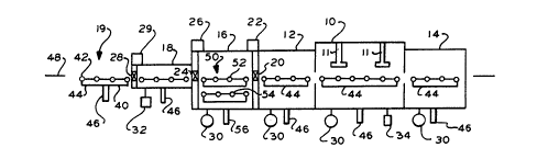
Figure 1 illustrates a single-ended vacuum processing
apparatus comprising a processing chamber 10, a holding chamber
16, and a lock chamber 18. The vacuum process may be a coatin~
process in whic~ workpieces are transported from an entry
buffer 12, passed a number of sputter coating sources 11 in the
processing chamber and into an overrun buffer 14. The
workpieces may be transported back and forth through the
processing cl~amber 10 as required.
1 307759
The processing area of the apparatus is separated from
the holding chamber 16 by a first internal gate valve 20 which
may be opened or closed as desired by an actuator 22. The
holding chamber 16 and the lock 18 are interconnected by a
second internal gate valve 24 activated by an actuator 26.
Access to the lock 18 from a workpiece loading and unloading
area 19 is by a external gate valve 28 operable by an actuator
29. The gate valves and actuator may be of conventional design
suitable for transferring workpieces of the desired size and
shape. One such gate valve is shown in U.S. Patent 4,065,097
to Timin.
Each of the chambers of the processing apparatus is
separately evacuable by conventional means. Lock 18 is
evacuable by a blower or other mechanical pump 32. For
sputtering or electron beam heated coating processes, holding
chamber 16 and the processing chamber 10 are preferably
evacuable by diffusion pumps 30. Processing chamber 10 may be
provided with a source 34 of a desired sputtering gas.
Each chamber of the vacuum processing apparatus is
provided with a conveyor for supporting and transporting
workpieces. For glass sheets and similar substrates, each
conveyor preferably comprises a series of parallel, horizontal
rollers 42 mounted on a frame 44 and driven by a reversible
motor 46. Preferably the conveyors in the separate chambers
are aligned to pass substrates into and out of the apparatus
along a pass line 48.
1 307759
In the preferred apparatus, the holding chamber 16 is
provided with a multi-level transporting device 50 which moves
vertically and which includes two horizontal conveyors 52 and
54 mounted one above the other on a common frame 60. As shown
in Figures 2, 3a and 3b, the frame 60 comprises two parallel
upper longitudinal members 62, interconnected by a number of
cross members 63, and two parallel lower longitudinal members
64, interconnected by a like number of cross members 65 aligned
directly below the upper members. The upper and lower members
are connected by a number of uprights 66.
When frame 60 is in its lower position (shown in Figs.
2 and 3b) it rests on legs 68 which are adjustable as necessary
to ensure that the frame rests level on the bottom wall 17 of
holding chamber 16. Additional legs and additional cross
members between the side members may be provided as necessary
depending upon the length of the workpiece transporting device.
In Figures 2, 3a and 3b, the upper conveyor 52 of
device 50 is aligned with the pass line 48. An elevator is
provided in order to raise the frame 60 so that lower conveyor
54 is at the pass line. As shown, the elevator comprises four
ball screw jacks 70 wl~ich extend externally of the chamber 16
through vacuum seal assemblies 71 in the bottom wall 17. Each
jack is provided with an oiler 75 to lubricate the seal
assembly. Alternatively, the elevator may comprise hydraulic
or pneumatic cylinders.
1 307759
Vertical motion of the transporting device 50 is
guided by four lateral guide wheels 72, two of w~lich are
attached to the external face of each lower longitudinal member
64. The wheels roll along upper 73 and lower 74 bar ways
mounted on opposite side walls of chamber 16. The motion of
the device 50 is also guided by a longitudinal guide wheel 76
mounted on an axle 77 perpendicular to one of the lower
longitudinal members 64. Wheel 76 rolls between two upper ways
78 and two lower ways 79 mounted on one side wall 15 of chamber
16. The upper and lower ways for guide wheels 72 and 76 are
aligned so that the device 50 is properly aligned in its raised
and lowered positions, respectively.
A number of rollers 80 are mounted for rotation in
bearing blocks ~2 aligned along side rails ~2 (the blocks 82
are omitted from Fig. 2). One end of the axle 83 of each
roller is fitted with two pulleys 84 and 85. As shown in Fig.
3a, corresponding pulleys of adjacent rollers are
interconnected by belts 86 which ensure that the rollers turn
simultaneously in the same direction.
The axle of one roller of whichever conveyor is at the
pass line is coupled by a magnetic means 90, 92 to shaft 94
which extends through a rotary seal in side wall 15. The
rotating shaft is driven by a reversible motor 95 outside
chamber 16.
Figure 4 illustrates t'ne method of tne invention.
Eac'n part of the figure illustrates a processing chamber 100, a
1 307759
holding cl~amber 16 and a lock 18; The processing chamber may
comprise entry and overrun buffers. Processing chamber 100 and
holding chamber 16 are interconnected by a first gate valve
20. Processing chamber 16 and lock 18 are interconnected by a
second gate valve 24. Workpiece access to lock 18 is provided
by a third gate valve 28. Processing chamber 100 contains a
first conveyor 101 and the lock 18 contains a second conveyor
102. As previously described, holding chamber 16 contains a
workpiece transporting device 50 having two conveyors, upper
level 52 and lower 54, and an elevator for aligning each
conveyor with the pass line 48 through the vacuum processing
apparatus.
In Figure 4a, valves 20 and 24 are closed. One
workpiece 110 is undergoing processing in chamber 100 and an
unprocessed workpiece 112 is waiting on the lower level 54 of
the transporting device 50 in holding chamber 16. Since valves
20 and 24 are closed, chamber 16 may be evacuated by a
diffusion pump and the pressure in the processing chamber 100
may be independently established, as desired. Valve 28 is open
in order that a second unprocessed workpiece 114 may be
transported from conveyor 104 in the loading and unloading area
onto conveyor 102 inside the lock as illustrated in Fig. 4b.
Valve 28 may then ~e closed and lock 18 evacuated by a roughing
pump.
1 30775q
Transporting device 50 is aligned so that the vacant
conveyor 52 is at the pass line. When processing of workpiece
110 is completed, valve 20 is opened and workpiece 110 is
transported onto the vacant upper conveyor 52. The
transporting device 50 then moves upward so that the lower
conveyor 54 is at the pass line, as shown in Fig. 4c, and the
unprocessed workpiece 112 is transported onto the conveyor 101
in the processing chamber. Valve 20 i6 closed so that
processing of workpiece 112 may proceed. Valves 24 and 28
remain closed so that rough pumping of lock 18 continues.
As illustrated in Fig. 4d, valve 24 is opened and
unprocessed workpiece 114 is transported into holding chamber
1~ onto the lower conveyor 54 of device 50. Then device 50 is
moved down so that the upper conveyor 52 is aligned at the pass
line, as shown in Fi~. 4e, and processed workpiece 110 is
transported through valve 24 onto conveyor 102 in lock 18, as
shown in Fig. 4f. When this has been completed, valve 24 is
closed. Valve 20 remains closed so that processing of
workpiece 112 continues in chamber 100. Lock 18 is vented and
gate valve 28 opened to enable the transfer of processed
workpiece 110 out of lock 18 onto conveyor 104. Valves 24 and
20 are closed so that the pumping of holding chamber 16 and the
processing in chamber 100 to continue. The processed workpiece
110 is unloaded from conveyor 104 and replaced with an
unprocessed workpiece and the the cycle continues, starting
again with Fig. 4a.
--8--
1 30775q
Use of a holding chamber can reduce gas bursts into
the processing chamber when gate 20 is opened and enables
pumping of lock 16 except for the time required to transport
workpieces through gate 28 as indicated in Figs. 4a and 4f.
Efficient utilization of the processing equipment is ensured
because processing may be continued except for the short time
required to transfer workpieces between processing chamber 100
and holding chamber 16 as indicated in Figs. 4b and 4c.
As described in connection with Fig. 4, processed
workpieces were placed on upper conveyor 52 and unprocessed
workpieces were placed on lower conveyor 54. If falling debris
is a problem, it may be preferable to modify the method so that
processed workpieces are placed on the lower conveyor 54 below
the unprocessed workpieces.
Various other modifications to the method and
apparatus may be made without departing from the spirit of the
invention which is defined by the following claims.