Note: Descriptions are shown in the official language in which they were submitted.
1 307861
70840-134
ELECTRONIC LIGHT POINTER FOR A PROJECTION MONITOR
FIELD OF INVENTION
This invention relates to cursor positioning devices
for computer systems, and more particulary to a cursor
positioning device in the form of an elongated pointer for
use with a projection display monitor and screen.
BACKGROUND
._
Computer systems generally incorporate a display
monitor unit having a cathode ray tube for providing a
visual representation of selected data to a user. A
specific point on the display is often indicated to the
user by way of a brightly illuminated cursor. In various
applications, the cursor may be moved by the user to any
desired point on the display, for example, to edit tex~
files or select menu options.
, ~
'
~ ..... ~ . ,
: . : .
,
1 30786 1
In the earlier prior art, the positioning control for
the cursor was typically provided by keys which were are
manually depressed by the user to incrementally move the
cursor across the screen. To overcome the awkwardness of
pressing keys multiple times to move the cursor across the
screen, other input devices were devised, such as the
light pen.
The light pen is positioned wlth its tip pointed
toward the display face of a direct view CRT display. The
tip of the
light pen lncludes an optical sensor for detecting the
raster scan trace as it excites the phosphors in the face
of the cathode xay tube. The timing of the detected
raster scan signal is translated into positional data,
which, in turn, is used by the computer software to
::
control the position o the cursor on the screen. As the
user moves the tip of the light pen across the face of
the cathode ray tube, the cursor moves along with it,
giving the user the direct interactive "feel" of drawing
on~the CRT face.
One disadvantage of the light pen is its low
resolution. Prior art light pens can sense an area of
~ :: ~ : :
2 -
~: .
:
1 30786 1
the display screen only as small as a character, instead
of a pixel, or picture element, so that lines drawn on a
screen often appear as blobs of light. This is caused
primarily by the large size of the optical sensor element
compared to the small size of the pixels on the display
screen, the persistence of the excited phosphor on the
screen, and parallax effects caused by the thick glass of
the cathode ray tube face.
The disadvantages of the light pen are overcome
somewhat by cursor positioning devices such as the
"mouse", the joystick, and th~ graphics input tablet,
which provide improved resolution and ease of use.
However, these alternative cursor positioning devices do
not provide the direct interactive "feel" provided by
light pens. Instead, the user manipulates these davices
on a table top, for example, and this effects a
corresponding movement of the cursor on the display screen.
~ here there is a need for a large number of users to
view displayed data, many computer systems have been
adapted to use projection monochrome monitors instead of
direct view CRT displays. With this type o monitor, a
video image is projected on a screen having a diagonal
measurement of three to five feet. Although first used
- 3 -
:
"~
1 30786 1
only for the display of video programming, the projectiondisplay monitor is becoming a popular computer display
device foe group viewing situations, such as computer
training classes, executive meetings, and conferences.
The use of a projection display monitor could be
greatly enhanced by a cursor control device that would
provide for moving the displayed cursor, selecting items
on menus, drawing on the projection screen, and calling up
files and display windows, the same way a user of a does
with a conventional "mouse" device. It would also be
desirable if the user could interact directly with the
projected image on the screen, similar to the way a light
pen is used with a direct view CRT display unit. In this
way, ~he actions o~ the user would be readily visable to
the viewing group. It would be urther desirable if the
motion of the cursor could be resolved to the pixel level,
making possible the writing or drawing fine lines on the
~.~
screen.
According, it is an object of the present invention to
provide a cursor positioning device for a projection
~- ~ monitor and display screen;
::
~ :.
'~:
- 4 -
:: ~
'
1 30786 1
It is another object of the present invention to
provide a cursor positioning device which allows the user
to interact directly with the projected image; and
It is a further object of the present invention to
provide a cursor positioning device having a high degree
of resolution.
SUMMARY OF THE INVENTION
In accordance with the present invention, a novel
light pointer is provided for a computer using a
projection display monitor and screen, whereby direct
interactive aontrol o a cursor is obtained. The present
invention provides a~user with the capability of walking
up to the screen, as in a classroom, positioning the tip
of the light pointer on the displayed image, and moving
the cursor, selecting menus, drawing figures, and
performing other control functions, with a resolution
:
close to one pixel.
In the present invention, a conventional mono~hrome
projection monitor projects images of display data on a
vertically oriented, wall mounted screen, by means of a
raster scanned projection tube. This creates a projected
s
.
~;
.
1 3 0 7 8 6 1 70840 l34
image of generally three to five feet diagonal, allowing
the displayed image to be viewed by a large number of
users, as in a classroom or conference room. The
projection monitor receives video and timing signals from
a computer.
In the preferred embodiment, the light pointer of the
present invention is a wireless, battery-powered unit, and
has a physical appearance not unlike that of a pointer
used with a blackboard in classroom situations. The light
pointer includes an elongated, cylindrical housin~ and is
provided with a telescoping inner cylinder to permit a
user to adjust the length of the housing for moving the
tip to any point on the screen without creating shadows.
The housing includes a handle portion including a select
switch for~performing computer control operations and a
tlp. The tip includes a flexible member and a light
sensor for detecting the raster scan trace emitted from
:
: the projection tube at a user selected location on the
s~creen. The light pointer contains circuitry for creating
a timed electrical signal, in response to the detected
raster scan trace, which is representative of the selected
location o the tip on or near the screen surface.
~ :
. ~ :
~ 6 -
1 30786 1
The light pointer is linked to an interface by means
of an FM transmitter/receiver arrang~ment. The interface
circuitry includes a microcontroller which determines the
location of the light sensor on the screen by means of the
timed electrical signal received from the light pointer.
The interface translates the timing of this detected
signal into vertical scan line and pixel position data,
and transmits this position in the form of X and Y
coordinate data to the video display controller of the
computer, by a serial bus. The computer, in turn,
generates cursor signals adapted for controlling the
position of the cursor on the screen o the projection
display monitor.
,
:
In operation, the user holds the light pointer on or
near the screen and aims the llght sensor at the
projection tube, not at the screen. When the tip of the
~ .;
light pointer is rested lightly against the screen at a
selected~location, the flexible member aligns the sensor
perpendicularly to the face of the projection tube so that
it will receive the maximum intensity of projected image
fleld from the projection tube.
7 -
,
.~
1 307~61 70~40-134
In the office environment, for example, where ten or
fifteen people may be present in a srnall conEerence room, the
light pointer gives the user the capability of calling up files
and editing data on the screen, by means of the select SWi tch
provided, in a directly interactive manner, while providing
commentary to the audience. The projected image on the screen
becomes, in a very basic sense, an electronic blackboard.
Furthermore, in the projected image, since the raster
has been expanded considerably, each pixel element is very close
to the size of the light sensor, and very fine movement of the
cursor may be effected. This feature is especially useful in
writing on the projected image, or drawing representations of
graphical data. High resolution of this type is generally not
possible with direct view CRT displays using light pen input
devices.
The invention may be summarized, according to one
aspect, as a cursor positioning system for a computer system
having a projection display monitor including a screen, com-
i
prising light sensor means for detecting a raster scan traceat a selected location near the surface of the screen of the
projection display monitor; means responsive to said sensor
means for generating position signals representative of the
selected location on the screen of the projection display
monitor; means ~or generating cursor signals adapted for con-
trolling the position of a cursor on the screen of the
projectlon display monitor in response to said position signals,
,
~ 8-
: .
~:
':
~`
`
1 307~61
70840-134
whereby said light sensor means designates a high resolution
cursor on said screen of the projection display monitor, said
high resolution cursor having a resolution close to one pixel.
According to another aspect, the invention provides a
computer display system comprising: a computer; a projection
video display monitor for projecting raster scanned image data,
coupled to said computer; a screen for displaying said image
data; a light pointer, the pointer including means for detecting
a raster scan trace at a selected location near the surface of
the screen of the projection display monitor and means for
genera-ting a timed electrical signal in response to the raster
scan trace; interface means, coupled to the light pointer and
the computer, for translating the timed electrical signal into
position signals representative of the selected location on the
screen; the computer generating cursor signals adapted for
controlling the position of a cursor on the screen of the
,
projection display monitor in response to said position signals;
whereby said light pointer designates a high resolution cursor
on said screen, said high resolution cursor having a resolution
close to one pixel.
According to a further aspect, the invention provides
a pointer device for controlling the position of a cursor in a
computer system having a projection display monitor including a
screen, comprising an elongated housing, having a handle portion
and a tip; said tip including a light sensor for detecting a
raster scan trace at a selected location near the surface of the
.
-8a-
, ~, ",.. ..... .
1 307~61 708~0-13~
screen of the projection display monitor; signal generating
means, coupled to said light sensor, for generating a timed
electrical signal in response to the detected raster scan trace;
and interface means, coupled to the light pointer and the com-
puter, for translating the timed electrical signal into position
signals representative of the selected location on the screen;
whereby the computer generates cursor signals adapted for con-
trolling the position of a cursor on the screen of the
projection display monitor in response to said position signals;
and whereby said tip of said pointer device designates a high
resolution cursor on said screen of the projection display
monitor, said high resolution cursor having a resolution close
to one pixel~
~ .
-8b-
: "
1 30786 1
DESCRIPTION OF THE DRAWINGS
FIG. 1 illustrates in block form the major components
of the system embodying the present invention;
FIG. 2 is a plan view of the light pointer of the
present invention;
FIG. 3 schematically shows the proper orientation of
the light pointer when in use;
::
FIG. 4 presents a block schematic diagram of the light
pointer of the present invention;
:
: FIG. S, a presents a block schematic of the interface
used with the present invention; and
FIG. 6 illustrates the timing diagrams associated with
the interface used with the present invention.
DESCRIPTION OF THE PREFER~ED EMBODIMENT
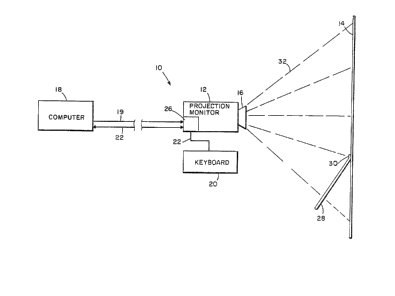
Turning attention first to FIG. 1, a video projection
system 10 is shown which uses the present invention. A
g _
~-:
, ~.,.,~ ,, ,~
1 307~6 1
projection monitor 12 projects images on a screen 14. The
screen 14 is oriented vertically, and preferably mounted
on a wall. The monitor 12 is a conventional monochrome
projection type, employing a projection tube 16, and would
preferably be used for projecting images of computer
display screens, including alphanumeric characters,
graphical data, and computer menus. As such, the
projection monitor 12 and screen 14 employed herein are
used identically to a direct view CRT display terminal
unit employed in a conventional computer system. It is
also important to note that the projection monitor 12 uses
standard raster scanning, in which the timing of the
displayed image data is determined by horizontal and
vertical sync pulses.
W1th a projection monitor 12 of the described type,
the image size projected on the screen 14 generally has a
diagonal dimension of three to five feet. This is for the
purpose of making the displayed image visable to a large
number of viewers, as when the video projection system 10
is used in a classroom environment, a lecture hall, or an
executive conference room. However, the principles of the
present invention are applicable to rear projection video
monitors, which incorporate a projection tube and
translucent screen in a single unit and project the image
:
1 0 -
,
.
', : . , ,
. ~ . .
1 30786 1
from behind the screen. And Further, although the
preferred embodiment employs a monochrome projection
monitor 12, color monitors of various types may also be
used.
The projection monitor 12 receives video and timing
signals from a computer 18 by means of a monitor cable
19. The computer 18 is also coupled to a keyboard ~0 by
means of a serial bus 22. The serial bus 22 carries
keyboard control and data signals to and from the computer
18. The serial bus 22 also carries data to the computer
18 from an interface unit 26, which operates with the
present invention and will described in more detail
further on. By using the configuration described, the
projection monitor 12 and keyboard 20 can conveniently be
placed on a table top, and the computer 18 can be located
some dlstance away, coupled to the keyboard 20 by the
serial bus 22 cable and the monitor cable 19.
:: :
A light pointer 28, according to the present
invention, is shown in FIG. l, oriented with its tip 30
near~the screen 14, within the raster scanned image field
32 emitted from the projection tube 16. The purpose of
;; the light pointer 28 is to detect the individual raster
; ; scan trace emitted from the projection tube 16 at a
,
.
:
,
1 3 0 7 8 6 I 708~0-134
selected location on or near the screen 14 and to provide
a timed electrical signal to the interface 26, which is
related to the location of the tip 30 on or near the
screen.
The light pointer 28 is linked to the interface 26 by
means of.an FM transmitter/receiver arrangement, which - -
will be:described. Used with the other elements of the
present invention, the light pointer 28 is a versatile
cursor control device for the screen 14. The light
pointer 28 performs functions equaling those of "mouse"
lnput devices, graphics input tablets, or light pens used
with conventional direct view display units. The user is
provided with the capability of moving a displayed cursor,
select~ing~menus, drawing figures, and other interactive
functions, with a r~esolution.close to one pixel.
Turning now to-~FI~ .2,.the light pointer 28 is shown
in more detail. The light pointer 28 includes an
elonq~ted.,:.~yli~dr.ical hou~i~g:.34., preferably~ fabricated
r:om a~durable, met~alL.ic material,-to shield the-
;componentsj~of the l.ight pointer:28.from.magnetic.fields
associated with the~projectlon monitor 12.
12 -
,
' '''
:
1 30786 1
The housing 34 separates at collar 36 and includes an
inner cylindrical member 37 to provide a telescoping
action which permits a user to adjust the length of the
housing 34, as desired. In the preferred embodiment, the
length of the housing 34 may be varied rom 12 to 20
inches. Ideally, the housing 34 should be long enough to
allow the user to select a position on the screen 14
without putting his hands or arms into the image field
32. This minimizes shadows on the screen 14.
The housing 34 includes a handle portion 38 for
gripping the light pointer 28. A SELECT switch 40,
included in the handle portion 38, may be conveniently
activated by the user's thumb pressure. It is within the
scope of the present invention for additional switches to
be included in the handle portion 38 with unctions such
.
as RETURN and EXæCUTE. These are conventional functions
for the manipulation of displayed data or graphics in a
computer system having a "mouse" input device. Switch 41
provides power to the light pointer 28.
'~: :
The tip 30 includes a flexible member 42 and a light
sensor 44. The light sensor 44 is or detecting the
raster scan trace emitted from the projection tube 16. In
13 -
.,.,,,;~,~.,... , .. ~ ,
1 30786 1
operation, the user holds the light sensor 44 near the
screen 14 at a selected location and aims the light sensor
44 at the projection tube 16, not at the screen 14;
therefore, the raster scanned image field 32 is detected
as it approaches the screen 14, rather than as it is
reflected off the screen 14. The light sensor 44,
therefore, detects a focused, high intensity light
source. Operating off the reflected image, the light
pointer would not be as sensitive.
In FIG. 3, the light pointer 28 is shown in the
correct operating relationship with the screen 14. The
light pointer 28 is held lightly against the screen 14 or
slightly away from it. The flexible member 42 functions
to align t~e light sensor 44 generally perpendicular to
the face of the projection tube 16 so that it will receive
the maximum intensity of the projected image field 32 from
the projection tube 16.
Turning now to FIG. 4, a block schematic diagram of
the~llght pointer 28 is shown. The circuitry of light
pointer 28 is primarily for detecting the individual
raeter scan trace at the location of the light sensor 44
relative to the screen 14, and for generatiny a timed
electrical signal representative of that location. The
- 14
.~
: : :
'~'`~'' '
~. ,
1 307861
timed electrical signal is transmitted to the interface
26, which determines the position of the light sensor 44
in relation to the vertical scan line and pixel position
in that display frame.
In the preferred embodiment, the light sensor 44 is a
photodiode. The light sensor detects the raster scan
trace and presents a pulse to the input of an AC coupled,
high-frequency amplifier 46. The amplifier 46 has a very
high gain level, in order to ensure that it detects the
low background level raster scan pulse.
The amplifier 46 is provided with an automatic gain
control 48. The automatic gain control 48 is needed to
compensate for variations in the brightness of the image
field 32. It is desirable for the amplifier 46 to
funation at same output amplltude level, with bright or
dark pictures or in bright or dark areas of the screen,
without becoming saturated and to ensure uniform operation.
The automatic gain control 4S monitors the output of
the amplifier 46 by sensing two threshold vol~age levels.
When the automatic gain control 48 senses a high level
output voltage, it decreases the gain o~ the amplifier 4~;
when it senses a low level output voltage, it increases
~ ~ :
the gain of the amplifier 46.
~ 15 -
::: :
1 307~6 1
A Schmitt trigger 50 is used to square up the edges of
the amplified analog pulse rece.ived from ampliier 48.
The output of the Schmitt trigger is a logical low until
the input signal reaches a threshold level, at which time
` the output goes high and remains high.
:
The ligbt pointer 28 is wireless, and an FM
transmitter 52 and antenna 54 is used to transmit the
amplified, squared raster scan pulse, in the form of a
timed electrical-signal to the interface 26. The FM
transmitter 52 was selected because the time delay
introduced in FM transmission is of a fixed value, and
this delay is easlly compensated for by the software in
the computer 18. Power for the light pointPr 28 is
~ .: :
provided by battery supply 56. The power switch 41
controls the battery supply. A select switch 40 for
selecting and manipulating data is coupled to the
: : :
transmitter 52.
;~ Turning now to FIG. 5, a block schematic diagram of
the interface 26 is shown. The interface 26 is contained
on a circuit card in the projection monitor and includes
the circuitry ~or determining the position of the light
;; sensor 44 on the screen 14.
16 -
,
~. ~
:;` :~::
.. , .. ~, .: ,
1 307861
: A microcontroller 60 (Motorola type MC68701) and
associated circuitry control the interface between the
light pointer 28 and the serial bus 22. The
microcontroller 60 detects the timed electrical signal
transmitted from the light pointer 28, translates the
timing of this detected signal into vertical scan line and
pixel position data, and finally transmits this position
in the form of X and Y coordinate data to the ~ideo
display controller of the computer 18, by the serial bus
22. This occurs 6n times per second.
":
The microcontroller 60 receives vertical sync 62 and
: horizontal sync 64 inputs from the video display
controller in the computer 18, which are also presented to
the display circuitry of the projectîon monitor 12. As is
well known to those skilled in the art, each vertical sync
pulse starts a new ~rame of displayed data in projection
monitor 12, and each horizontal sync pulse starts a new
scan line. This relationship can be appreciated by
considering the first two timing signals illustrated in
: FIG. 6.
The detected signal is received by an FM receiver 66
~ and antenna 68 and amplified through an amplifier 70. The
:` ,
~: - 17 -
~ ::
~ '' ' . ' .
,
.
1 307~6 1
leading edge of the detected signal indicates the location
of the light sensor 44, as shown in the third timing
signal of FIG. 6. The microcontroller 60 receives the
detected signal and determines the frame and vertical scan
line where the light sensor 44 is located by means of the
vertical sync and horizontal sync pulses. However, pixel
position is more difficult to determine, firstly, because
there are no pixel timing signals coming from the video
generator board in the computer 18, and secondly, because
the frequency of the pixels is faster than the
microcontroller 60 can count.
:
The microcontroller 60 determines pixel position in
the scan line by means of a phase lock loop arrangement
which functions as a pixel counter, dividing each scan
line into 1024 positions. The phase locked loop includes
the pulse width control output 72 of the microcontroller
60, an integrator 74, a voltage controlled oscillator 76,
~ ~ a ten bit counter 78, and a return loop 80.
:::
The voltage controlled oscillator 76 operates
continuously at approximately 20 MHz. The output, or VCO
clock, is presented to the ten bit counter 78. The output
; pins (Q0 - Q9) of the counter 78 are connected to a latch .
82, which will be described. The highest order bit (Q9)
~:
~ ~ .
.. ~ .
.
1 307~61
is also presented to the microcontroller 60 through the
return loop 83. At a count of 1024, the Q9 output of the
counter 78 goes high.
The microcontroller 60 compares the horizontal sync
pulse with the Q9 output and matches the timing of the two
signals by varying the duty cycle of output 72. The
output 72 signal is presented to integrator 74, which
outputs a variable DC signal that controls the frequency
of the voltage controlled oscillator 76.
This phase lock loop arrangement ensures that the
leading edge of each horizontal sync pulse will be
synchronized with the leadiny edge of the Q9 output of
counter 78. Therefore, every time a horizontal sync pulse
occurs, starting a new scan line, the counter 78
accurately increments through 1024 pixel positions for
that scan line. This provides a very high resolution of
pixel position. This relationship is illustrated in the
four bottom timing diagrams in FIG. 6.
'
At the same time the detected raster signal is
received by the microcontroller 60, an RS flip-flop 84
sets the latch 82, which receives the outputs (Q0-Q9) of
~: the counter 7~. The latch 82 holds pixel position of
::` -- 19 --
:
~, . ., ,. ~ , .
--` 1 30786 1
70840-134
light sensor 44 in the scan line. The RS flip-flop and latch 82
are reset at the start of the next frame by the vertical sync
pulse.
The vertical scan line and pixel position, in the form
of X and Y coordinate data, are transmitted to the video display
controller of the computer 18 over the bus 22. The computer 18
provides means for generating cursor control signals adapted for
controlling the position of the cursor in response to the position
: signals received from the interface 26.
In operation, the user holds the tip of the light
pointer on or near a selected location on the screen and aims the
light sensor at the projection tube. When the tip of the light
pointer is rested lightly against the screen at a selected loca-
i tion, the flexible member aligns the sensor perpendicularly to the
:~ face of the projection tube so that it will receive the maximum
amount of intensity of the image field from the projection tube.
~ In a classroom or executive office environment where a
:~ number o~ persons may be viewing the projected computer display,
the user has the capability of calling up files and editing data
~ on the screen, by means of the select
20 -
": ` . :
.
~ 307~6 1
switch provided, in a directly interactive manner, while
providing commentary to the audience, or by direction from
viewers in the audience. The projected image becomes, in
a very basic s~nse, the computer display equivalent of an
electronic blackboard.
Furthermore, in the projected image, since the raster
has been expanded considerably, each pixel element is very
close to the size of the light sensor, and very fine
movement of the cursor may be effected.
High resolution is gener;ally not possible with direct
view CRT displays using light pen input devices. In a
: '
;~ conventional direct view video display monitor with a
~ standard 12 inch diagonal screen having a resolution of
!
800 x 300 pixels, the width of the screen is approximately
eight inches, and the diameter of each pixel is therefore
.Ol inches. When the screen size is expanded, as in the
present invention, to an image area having a five foot
::
diagonal dimension, the width of the projected image is
approximately four feet. With a resolution of 800 dots
per inch, each pixel now has a diameter of approximately
.125 inches, which is also the approximate size of the
light sensor. The high pixel resolution o~ the present
invention makes it possible ~or a user to create fine
lines on the projected image, as in writing or drawing.
'~
`''''''~''~
~:
1 3078~ ~
The closer the light pointer is held to the screen,
the greater the accuracy, because the image field has been
e~panded to its maximum area. However, the light pointer
does not require actual contact with screen to function
properly. Still, it is desirable to keep the light
pointer close enough to the screen to minimize shadows on
the screen from the light pointer housing. Shadow effects
caused by the operators hands or arms are eliminated by
adjusting the length of the pointer housing so that all
positions of the screen may be selected without the hands
of the user intruding in the image field.
; In view of the above~ it will be seen that the several
objects of the present invention are readily achieved and
~` ~ other advantageous results attained.
Obviously many modifications and variations of the
present invention are possible in light of the above
teachlngs, without departing`from the spirit and scope of
the invention. The novel light pointer disclosed herein
, ~ :
is applicable to a wide range of uses. In view of this,
it is understood that the above description is
illustrative rather than limiting.
- 22 -
~: