Note: Descriptions are shown in the official language in which they were submitted.
1307913
METHOD OF MAKING CERAMIC COMPOSITE ARTICLES BY INVERSE
SHAPE REPLICATION OF AN EXPENDABLE PATTERN
Background of the Invention
The present invention broadly relates to methods of
making ceramic composite bodies having one or more shaped
cavities thereln. In particular, the invention relates io
methods of making ceramic composite bodies comprising a
polycrystalline ceramic matrix infiltrating a bed of filler
and having at least one cavity of selected geometry formed by
inversely replicating the shape of an expendable pattern.
Description of Commonly Owned Patent Applications
The subject matter of this application is related to
that of copending Canadian Patent Application Serial No.
528,275, filed January 27, 1987, entitled "Inverse Shape
Replication Method of Making Ceramic Composite Articles and
Articles Obtained Thereby" in the names of ~arc S. Newkirk et
al. This copending application discloses a novel oxidation
method for producing a self-supporting ceramic composite body
having therein at least one cavity which inversely replicates
the geometry or shape of the parent metal precursor as the
positive pattern. Thus, the resulting composite product has
a cavity of a predetermined geometry. This application is
discussed in greater detail below. Composites generally
utilizing the same oxidation phenomenon, but having no
defined or predetermined configuration, are disclosed in
Canadian Patent Application Serial No. 500,994, filed
February 3, 1986, now Canadian Patent No. 1,271,783 which
issued July 17, 1990, in the names of Marc S. Newkirk et al.
and entitled "Composite Ceramic Articles and Methods of
Making Same." The application and patent disclose a novel
method for producing a self-supporting ceramic composite by
growing an oxidation reaction product from a parent metal
into a permeable mass of filler.
The method of growing a ceramic product by this
oxidation reaction is disclosed generally in copending
Canadian Patent Application Serial No. 476,692 filed March
.~' ~
: .:.. ~. ...
1307913
15, 1985, now Canadian Patent No. 1,257,3000 which issued
July 11, 1989 in the names of Marc S. Newkirk et al. and
entitled "Novel Ceramic Materials and Methods of Making the
Same." This patent discloses the method of producing
self-supporting ceramic bodies grown as the oxidation
reaction produc~ of a parent metal precursor which may be
enhanced by the use of an alloyed dopant. Molten parent
metal is reacted with a vapor-phase oxidant to form the
oxidation reaction product. In the appropriate temperature
range, molten metal is progressively drawn through the
oxidation reaction product and into contact with the oxidant
thereby continuing to form additional oxidation reaction
product and developing the ceramic body. The method was
improved upon by the use of external dopants applied to the
surface of the precursor parent metal as disclosed in
Canadian Patent Application Serial No. 487,146, filed July
19, 1985, in the names of Marc S. Newkirk et al. and entitled
"Methods of Making Self-~upporting Ceramic Materials".
There is an increased interest in substituting ceramics
for metals because, with respect to certain properties,
ceramics are superior to metals. There are, however, several
known limitations or difficulties in making this substitution
such as scaling versatility, capability to produce complex
shapes, satisfying the properties required for the end use
application, and costs. The above-described Canadian Patents
and Patent Applications overcome these limitations or
difficulties and provide novel methods for reliably producing
ceramic materials, including composites.
The invention described in Canadian Patent Application
Serial No. 528,275 (identified above) ameliorates the
difficulties in formation of ceramic hodies having shapes
with complicated internal cavities and especially shapes with
re-entrant cavities. Conventional or known methods for
making ceramic products with such shapes by compacting and
sintering particles are not readily applicable, because the
internal pattern required to establish the desired part
geometry cannot be easily removed after the body is formed
around it. While such part geometries can sometimes be
1 3079 1 3
prepared by machining or grinding the desired shape from
green preform or finished ceramic blank, this approach is
undesirable because of the high costs of machining and
grinding operations, especially when applied to ceramic
materials. In many cases such geometries cannot presently be
produced at all, even by machining or grinding.
The invention described in Canadian Patent Application
Serial No. 528,275 provides shaped cavity~containing ceramic
bodies typically of high strength and fracture toughness by a
mechanism which is more direct, more versatile and less
expensive than conventional approaches. The invention
described therein also provides means for reliably producing
cavity-containing ceramic bodies of a size and thickness
which is difficult or impossible to duplicate with the
presently available technology. Briefly, the invention
therein described involves embedding a shaped parent metal
precursor within a conformable filler, and infiltrating the
filler with a ceramic matrix obtained by oxidation of the
parent metal to form a polycrystalline material consisting
essentially of the oxidation reaction product of said parent
metal with an oxidant and optionally, one or more metallic
constituents. More particularly, in practicing the
invention, the parent metal is shaped to provide a pattern,
and then is surrounded by a conformable filler which
inversely replicates the geometry of the shaped parent metal.
In this method, the filler (1) is permeable to the oxidant
when required as in the case where the oxidant is a
vapor-phase oxidant and, in any case, is permeable to
infiltration by the developing oxidation reaction product;
(2) has sufficient conformability over the heat-up
temperature interval to accommQdate the differential thermal
expansion between the filler and the parent metal plus any
melting-point volume change of the metal; and t3) at least in
a support zone thereof enveloping the pattern, is
intrinsically self-bonding, whereby said filler has
sufficient cohesive stren~th to retain the inversely
replicated geometry within the bed upon migration o~ the
~i parent metal as described below. The surrounded shaped
1 3079 1 3
parent metal is heated to a temperature region above its
melting point but below the melting point of the oxidation
reaction product to form a body of molten parent me~al. The
molten parent metal is reacted in that temperature region or
interval with the oxidant to form the oxidation reaction
product. At least a portion of the oxidation reaction
product is maintained in that temperature region and in
contact with and between the body of molten metal and the
oxidant, whereby molten metal is progressively drawn from the
body of molten metal through the oxidation reaction product,
concurrently forming the cavity as oxidation reaction product
continues to fo~m within the bed of filler at the interface
between the oxidant and previously formed oxidation reaction
product. This reaction is continued in that temperature
region for a time sufficient to at least partially embed the
filler within the oxidation raaction product by growth o~ the
latter to form the composite body having the aforesaid cavity
therein. Finally, the resulting self-supporting composite
body is separated from excess filler, if any.
Summary of the Invention
The present invention provides an alternative method
for producing shaped, cavity-containing ceramic bodies. An
expendable or disposable pattern is surrounded or embedded
with a quantity of filler material. The pattern is then
eliminated and replaced by a quantity of parent metal, and
the oxidation reaction proceeds with the resulting oxidation
reaction product infiltrating the filler material as
described above in connection with the Canadian Patent
Applications. The geometry of the cavity inversely
replicates the geometry of the pattern.
In more detail, the method comprises shaping a
disposable or expendable pattern of any suitable material
such as plastic, foam, or wax. The expendable pattern is
packed within or surrounded with a bed of conformable filler
material to inversely replicate the geometry of the
expendable pattern in the bed. The pattern is then
eliminated, as for example, by vapori2ation, and replaced
.~ ' '
. -
1307913
with a quantity of parent metal; preferabl~ molten. The bed
and the body of parent metal contained within it are then
heated to a process temperature above the melting point of
the parent metal but below the melting point of the oxidation
reaction product. In this temperature interval, the molten
parent metal reacts with an oxidant, e.g., a vapor-phase
oxidant, to form the oxidation reaction product. At least a
portion of the oxidation reaction product is maintained in
contact with and bekween the body of molten metal and the
oxidant, and molten metal is progressively drawn from the
body of molten metal through the oxidation reaction product
toward said bed of filler to concurrently form the cavity in
said bed of filler as oxidation reaction product continues to
form at the interface between the oxidant and previously
formed oxidation reaction product. The reaction is continued
for a time sufficient to at least partially infiltrate or
embed the filler within the oxidation reaction product by
growth of the latter to form a composite body having a cavity
therein. Where desired, the boundaries of the filler bed may
be provided with a barrier means to substantially inhibit or
prevent growth there beyond so as to facilitate achieving a
net shape to the ceramic composite body. The resulting
self-supporting composite body is separated from excess
filler and/or parent metal, if any~
The bed of filler material is characterized by being
permeable to the oxidant when required as in the case when
ths oxidant is a vapor-phase oxidant, and being permeable to
infiltration by the developing oxidation reaction product.
The expendable pattern, which is packed in the filler
material, may be removed as by vaporization, solution,
melting and draining, or the like, prior to adding the parent
metal to ~he cavity. Metal is then added to the resulting
cavity either as molten metal, or as a solid and then melted
in place. In another embodiment, the molten parent metal is
poured onto the expendable pattern to vaporize the pattern.
Where desired, the bed of filler material possesses some
temporary bonding strength to maintain the desired shape in
the cavity. The oxidation reaction process is then conducted
I 30791 3
to form the composite.
Generally, it is relatively easy to shape an expendable
pattern material. For example, expendable pattern materials
such as expanded polystyrene can be extruded, molded, or
S injection molded with relative ease, and therefore it is
possible to produce by the present invention ceramic
composites with cavities having a complicated or intricate
cavity geometry or shape.
The product of this invention is a self-supporting
ceramic composlte body having therein a cavity which
inversely replicates the shape or geometry of the expendable
pattern and comprises a ceramic matrix having ~iller
incorporated therein. The matrix consists essentially of a
polycrystalline oxidation reaction product having
interconnected crystallites formed upon oxidation of the
parent metal precursor, and optionally metallic constituents
or pores or both.
The materials of this invention can be grown with
substantially uniform properties through their cross section
to a thickness heretofore difficult to achieve by
conventional processes for producing dense ceramic
structures. The process which yields these materials also
obviates the high costs associated with conventional ceramic
production methods, including fine, high purity, uniform
powder preparation: green body forming: binder burnout:
sintering or hot pressing and/or hot isostatic pressing. The
products of the present invention are adaptable or ~abricated
for use as articles of commerce which, as used hereln, is
intended to include, without limitation, industrial,
structural and technical ceramic bodies for such applications
where electrical, wear, thermal, structural or other ~eatures
or properties are important or beneficial, and is not
intended to include recycled or waste materials such as might
be produced as unwanted by-products in the processing of
molten metals.
As used in this speci~ication and the appended claims,
the terms below are defined as follows:
-~( "Ceramic" is not to be unduly construed as being
1 3079 1 3
limited to a ceramic body in the classical sense, that is, in
the sense that it consists entirely of non-metallic and
inorganic materials, but rather refers to a body which is
predominanily ceramic with respect to either composition or
dominant properties, although the body may contain minor or
substantial amounts of one or more metallic constituents
derived from the parent metal, or reduced from the oxidant or
a dopant, most typically within a range of from about 1-40%
by volume, but may include still more metal.
"Oxidation reaction product'l generally means one or
more metals in any oxidized state wherein a metal has given
up electrons to or shared electrons with another element,
compound, or combination thereof. Accordingly, an "oxidation
reaction product" under this definition includes the product
of reaction of one or more metals with an oxidant such as
those described in this application.
"Oxidant" means one or more suitable electron acceptors
or electron sharers and may be a solid, a li~uid, or a gas
(vapor) or some combination of these (e.g., a solid and a
gas) at the process conditions.
"Pattern material" refers to disposable or expendable
materials such as plastics, foams, and waxes which can be
extruded, molded, cast, machined, or otherwise shaped for
establishing the geometry of the cavity, and also which can
be chemically or physically removed from the bed of filler
material while leaving the cavity formed thereby
substantially intact.
"Parent metal" as used in this specification and the
appended claims refers to that metal, e.g., aluminum, which
is the precursor for the polycrystalline oxidaticn reaction
product, and includes that metal as a relatively pure metal,
a commercially available metal with impurities and/or
alloying constituents, or an alloy in which that met~l
precursor is the major constituent; and when a specified
metal is mentioned as the parent metal, e.g., aluminum, the
metal identified should be read with this definition in mind
unless indicated otherwise by the context.
'1 ~''! "Cavity" means broadly an unfilled space within a mass
1 3079 1 3
or body, and is not limited to any specific configuration of
the space.
Brief Description of the Drawin~s
FIGURE 1 is a schematic, cross-sectional view in
elevation showing an assembly of a pattern material
surrounded by a bed of parti~ulate filler and confined within
a refractory vessel;
FIGURE 2 is a perspective view similar to FIGURE 1
showing the addition of a parent metal to the cavity.
FIGURE 3 is a cross-sectional view of a cera~ic
composite body of FIGURE 1 made in accordance with the
invention.
Detailed_Description of the Invention and Pre~er~ed
Embodiments Thereof
In the practice of the present invention, a quantity of
a pattern material is provided in the form of an expendable
pattern, the geometry of which is to be inversely replicated
as a cavity within the finisned ceramic composite. By
following the practices of the present invention, complex
shapes can be inversely replicated within the finished
ceramic composite during formation or growth of the ceramic,
rather than by shaping or machining a ceramic body. The term
"inversely replicated" means that the cavity in the cexamic
composite attained by the invention process is defined by
interior surfaces of the ceramic composite which are
congruent to the shape of the expPndable pattern. The
pattern material may be suitably shaped by any appropriate
means; for example, a quantity of an e~pendable pattern
material may be suitably molded, extruded, cast, machined or
otherwise shaped. The pattern may have grooves, bores,
recesses, lands, bosses, flanges, studs, screw threads and
the like formed therein as well as having collars, bushings,
discs, bars, or the like assembled thereto to provlde
patterns of virtually any desired configuration. The pattern
may be hollow or may comprise one or more unitary pieces
suitably shaped so that when surrounded within a c~nformable
~; bed of filler, the pattern material de~ines a shaped cavity
.
1 3079 1 3
within the bed and occupies the cavity within the mass o~
filler.
When the expendable pattern material is eventually
replaced by a quantity of parent metal which is melted under
oxidation reaction conditions, a shaped cavity develops in
the resulting ceramic composite body. Thus, in one aspect,
the present invention provides the advantage of making the
cavity shape by molding, extruding, casting or machining an
expendable pattern material such as a plastic foam rather
than by forming, grinding or machining a ceramic, or by
shaping the parent metal precursor as taught in the aforesaid
Canadian Patent Application Serial No. 528,275.
The pattern materials which may be used in the present
invention include those materials which have been used in
conventional expendable mold casting techniques. Although
various expendable grade waxes or wax blends are suitable for
certain embodiments, expanded plastics and foams are
preferred. More preferably, polystyrenes, polyethylenes and
polyurethanes are used as the pattern materials.
The pattern material may be shaped by conventional
processes including injection molding, blow molding,
extrusion, casting, machining and the like. Injection
molding is currently preferred ~or making large numbers of
patterns. Blow molding also may be preferred in other
2~ embodiments for its ability to produce hollow expendable
molds. Blow molding may be particularly desirable because it
minimizes the amount of expendable material in order to
facilitate a more rapid evacuation of the cavity.
The expendable material may be eliminated or evacuated
from the cavity by various methods. In one embodiment, the
expendable pattern material may ~e vaporized by evaporation
or combustion prior to the addition of the parent metal
precursor. In alternative embodiments, the pattern material
may be removed by melting and allowing the material to drain
from the cavity. Any residue can be burned out as in a
prefiring step. The expendable pattern also may be dissolved
by chemical means, and any residue washed from the cavity by
use of a suitable solvent.
1 30 79 1 3
In still other alternative embodiments, the pattern
material is left in place until a quantity of molten parent
metal is poured directly into the cavity. When the molten
parent metal contacts the pattern, the material is vaporized
and thus eliminated from the cavity. In this way, molten
parent metal concomitantly replaces the evacuating pattern
material thereby reducing the chance of disturbing or
upsetting the bed of filler. As a result, the filler
material is more likely to retain the shape of the cavity.
Depending on the desired method of replacing the
pattern material with the parent metal, the parent metal may
be added in either molten or solid form, e.g., powder,
particulate granules or pieces. The use of a molten parent
metal is preferred because it completely fills the cavity at
or near the temperature at which the oxidation reaction will
occur. In addltion, when the parent metal is in a molten
state, a fresh surface of the parent metal is available for
the oxidation reaction process, i.e., the surface is free of
surface oxides, etc. Where desired, the filler bed and
expendable pattern may be placed in a furnace at or near the
; process temperature, and molten parent metal added to expel
the pattern. In this manner, as molten metal is added and
displaces the pattern which is being vaporized, the oxidation
reaction begins and infiltration of the bed occurs. In
alternative embodiments, the pattern is first displaced, and
then the parent mPtal is poured into the cavity. A powdered
; or granulated parent metal may be desirable in some
embodiments because interstices in the powdered or granulated
mass as a whole would accommodate thermal expansion of the
metal. Also, parent metal in powdered or granulated form,
when added to the cavity, would conform readily to the shape
of the cavity in the bed of filler material.
Although the invention is described below in detail
with specific reference to aluminum as the preferred parent
metal, other suitable parent metals which meet the criteria
of the present invention include, but are not limited to,
silicon, tltanium, tin, zirconium and hafnium.
~a~ A solid, liquid or vapor-phase (gas) oxîdant, or a
1 307q 1 3
11
combination of such oxidants, may be employed. ~or example,
typical oxidants include, without limitation, oxygen,
nitrogen, a halogen, sulphur, phosphorus, arsenic, carbon,
boron, selenium, tellurium, and compounds and combinations
thereof, for example, silica (as a source of oxygen),
methane, ethane, propane, acetylene, ethylene, and propylene
(as a source of carbon), and mixtures such as air, H,/H2O and
CO/CO2, the latter two being useful in controlling the oxygen
activity of the environment.
Although any suitable oxidants may be employed,
specific embodiments of the invention are described below
with reference to use of vapor-phase oxidants. IP a gas or
vapor oxidant, i.e., a vapor-phase oxidant, is used the
filler is permeable to the vapor-phase oxidant so that upon
exposure of the bed of filler to the oxi~ant, the vapor-phase
oxidant permeates the bed of filler to contact the molten
parent metal therein. The term "vapor-phase oxidant" means a
vaporized or normally gaseous material which provides an
oxidizing atmosphere. For example, oxygen or gas mixtures
containing oxygen (including air) are preferred vapor-phase
oxidants, as in the case where aluminum is the parent metal
and aluminum oxide the desired reaction product, with air
usually being more preferred for obvious reasons of economy.
When an oxidant is identified as containing or comprising a
particular gas or vapor, this means an oxidant in which the
identi~ied gas or vapor is tha sole, predominant or at least
a significant oxidizer of the parent metal under the
conditions obtaining in the oxidizing environment utilized.
For example, although the major cons_ituent of air is
nitrogen, the oxygen content of air is the normally sole
oxidizer for the parent metal because oxygen is a
significantly stronger oxidant than nitrogen. Air therefore
falls within the definition of an "~xygen-containing gas"
oxidant but not within the definition of a
"nitrogen-containing gas" oxidant. An example of a
"nitrogen-containing gas" oxidant as used herein and in ~he
claims is "forming gas", which contains 96 volume percent
nitrogen and 4 volume percent hydrogen.
~1~
;
13~)7~13
12
When a solid oxi~ant is employed, it is usually
dispersed through the entire bed of filler in the form of
particulates admixed with the filler, or perhaps as coatings
on the filler particles. Any suitable solid oxidant may be
employed including elements, such as boron or carbon, or
reducible compounds, such as silicon dioxide or certain
borides of lower thermodynamic stability than the boride
reaction product of the parent metal. For example, when
boron or a reducible boride is used as a solid oxidant for an
aluminum parent metal, the resu:Lting oxidation reaction
product is aluminum boride.
In some instances, the oxidation reaction may proceed
so rapidly with a solid oxidant that the oxidation reaction
product tends to fuse due to the exothermic nature of the
process. This occurrence can degrade the microstructural
uniformity of the ceramic body. This rapid exothermic
reaction can be avoided by mixing into the composition
relatively inert fillers which exhibit low reactivity. Such
fillers absorb the heat of reaction to minimize any thermal
runaway effect. An example of such a suitable inert filler
is one which is identical to the intended oxidation reaction
product.
If a liquid oxidant is employed, the entire bed of
filler or a portion thereof adjacent the molten metal is
coated or soaked as by immersion in the oxidant to impregnate
the filler. Reference to a liquid oxidant means one which is
a liquid under the oxidation reaction conditions, and so a
liquid oxidant may have a solid precursor, such as a salt,
which is molten at the oxidation reaction conditions.
Alternatively, the liquid oxidant may have a liquid
precursor, e.g~, a solution of a material, which is used to
impregnate part or all of the filler and which is melted or
decomposed at the oxidation reaction conditions to provide a
suitable oxidant moiety. Examples of liquid oxidants as
herein defined include low melting glasses.
The filler material utilized in the practice of the
invention may be one or more of a wide variety of materials
suitable ~or the purpose. As used herein and in the claims,
..,
1307ql3
13
when speaking of surrounding the expenda~le pattern with the
filler material, it is intended to refer to packing or
embedding the filler material around the expendable pattern,
or laying the filler material up against the expendable
pattern. The filler material should substantially conform to
the geometry of the expendable pattern. For example, if the
filler comprises particulate material such as fine grains or
powders of a refractory metal oxide, the pattern is
surrounded by the filler so that the pattern defines a filled
cavity (filled or occupied by the pattern). However, it is
not necessary that the filler be in fine particulate form.
For example, the filler may comprise wire, fibers, hollow
bodies, spheres, bubbles, pellets, platelets or aggregate, or
whiskers, or such materials as metal wool, wires, or
refractory fiber cloth. The filler also may comprise either a
heterogeneous or homogeneous combination of two or more such
components or geometric configurations, e.g., a combination
of small particulate grains and whis~ers. It is necessary
only that the physical configuration of the filler ~e such as
to permit the expendable pattern to be surrounded by or
within a mass of the filler with the filler closely
conforming to the surfaces of the pattern. The cavity
ultimately formed in the ceramic composite is the negative of
the geometry of the pattern material. This material
initially forms a (filled) cavity within the bed of
conformable filler, the cavity being initially shaped and
filled by the pattern material.
The filler material useful in the practice of the
invention is one which, under the oxidation reaction
conditions of the invention, is permeable when the oxidant is
a vapor-phase oxidant, to passage therethrough of the
oxidant. In any case, the filler also is permeable to the
growth or development therethrough of oxidàtion reaction
product. Where desired, the filler also has at the
temperature at which the oxidation reaction is conducted,
sufficient cohesive strength formed or developed, so as to
retain the geometry inversely replicated therein by
-;l conformance of the filler to the pattern material as the
:
1307913
14
pattern material is replaced by the parent metal.
It is desirable to peff orm the method of the present
invention in such a way so as to minimize the time between
the evacuation of the expendable pattern from the cavity and
the point at which the reaction product has formed in the
filler material to produce a shell of sufficient strength to
maintain the shape of the cavity. However, there will be a
transition period, though brief, when the shape of the cavity
is not maintained by the pattern material or the reaction
product. Thus, the filler material desirably possesses at
least some capacity to self--bond so as to maintain the shape
of the cavity by the filler material alone. Otherwise,
either the force of gravity on the filler or a pressure
differential between the developing cavity and the process
atmosphere could cause the cavity to collapse inwardly as it
is evacuated by the parent metal.
One method of maintaining the geometry of the cavity is
to use a self-bonding filler which, at the appropriate
temperature, either intrinsically sinters and bonds or can be
made to sinter or otherwise bond by appropriate additives or
surface modifications of the filler. For exampla, a suitable
filler for use with an aluminum parent metal utilizing an air
oxidant comprises alumina powder with an added silica bonding
agent as fine particles or coatings on the alumina powder.
Such mixtures of materials will partially sinter or bond at
or below the oxidation reaction conditions under which the
ceramic matrix will form. Without the silica additive, the
alumina particles require substantially higher temperatures
for bonding.
Another suitable class of fillers includes particles or
fibers which, under the oxidation reaction conditions of the
process, form a reaction product skin on their surfaces which
tends to bond the particles in the desired temperature range.
An example of this class of filler in the case where aluminum
is employed as the parent metal and air as the oxidant, is
fine silicon carbide particles (e.g., 500 mesh and finer),
which form a silicon dioxide skin bonding themselves together
in the appropriate temperature range for the aluminum
1 307ql 3
oxidation reaction.
In alternative embodiments, -the geometry of the cavity
can be maintained during the transition period by use of an
organic binder material which will be evacuated from the
filler material at or below the oxidation reaction
temperature.
It is not necessary that the entire mass or bed of
filler comprise a sinterable or self-bonding filler or
contain a sintering or bonding agent, although such
arrangement is within the purview of the invention. The
self-bonding filler and/or the bonding or sintering agent may
be dispersed only in that portion of the bed or filler
adjacent to and surrounding the expendable pattern of parent
metal to a depth sufficient to form upon sintering or
otherwise ~onding an encasement of the developing cavity
which is of sufficient thickness and mechanical strength to
prevent collapse of the cavity (and consequent loss of
fidelity of its shape in the grown ceramic body to the shape
of the expendable pattern) before a sufficient thickness of
the oxidation reaction product is attained. Thus, it
suffices if a "support zone" of filler enveloping the pattern
comprises a filler which is inherently sintera~le or
self-bonding within the appropriate temparature range or
contains a sintering or bonding agent which is effective
within the appropriate temperature range.
As used herein and in the claims, a ~Isupport zone" of
filler is that thickness of filler enveloping the pattern
which, upon bonding, is at least sufficient to provide the
structural strength necessary to retain the replicated
geometry of the expendable pattern material until the growing
oxidation reaction product becomes self-supporting against
cavity collapse. The size of the support zone of filler will
vary depending on the size and configuration of the pattern
and the mechanical strength attained by the sinterable or
self-bonding filler in the support zone. The support zone
may extend from the surface of the pattern material into the
filler bed for a distance less than that to which the
oxidation reaction product will grow or for the full distance
1 3079 1 3
16
of growth. In fact, in some cases the support zone may be
quite thin. For example, although the support zone of filler
may be a bed of filler encasing the pattern material and
itself encased within a larger bed of non-self-bonding or
non-sinterable filler, the support zone may in suitable cases
comprise only a coating of self-bonding or sinterable
particles adhered to the expendable pattern by a suitable
adhesive or coating agent. An example of this coating
technique is given below.
In any case, the filler should not sinter, fuse or
react in such a way as to form an impermeable mass so as to
block the infiltration of the oxidation reaction product
therethrouqh or, when a vapor-phase oxidant is used, passage
of such vapor-phase oxidant therethrough. Any sintered mass
which does form should not form at such a low temperature as
to fracture due to an expansion mismatch between the pattern
material and the filler before the vaporization temperature
is reached.
As noted previously, a bonding or sintering agent may
be included as a component of the filler in those cases where
the filler would not otherwise have sufficient inherent
self-bonding or sintering characteristics to prevent collapse
of the cavity being formed into the volume formerly occupied
by the expendable pattern. This bonding agent may be
dispersed throughout ~he ~iller or in the support zone only~
Suitable materials for this purpose include organo-metallio
materials which under the oxidizing conditions required to
form the oxidation reaction product will at least partially
decompose and bind the filler sufficiently to provide the
requisite mechanical strength. The binder should not
interfere with the oxidation reaction process or leave
undesirad residual by-products within the ceramic composite
product. Binders suitable for this purpose are well known in
the art. For example, tetraethylorthosilicate is exemplary
of suitable organo-metallic binders, leaving behind at the
oxidation reaction tempera~ure a silica moiety which
effectively binds the filler with the requisite cohesive
~a~l strength.
-
1307913
It is presently preferred to pre-heat the bed of filler
material before the parent metal is added thereto. In this
way, thermal shock to the bed can be avoided. It may be most
effective to heat the bed of filler material to the same or
higher temperature of the molten parent metal which is poured
into the cavity. After the pattern material has been
replaced by the parent metal in the cavity, the set-up of the
parent metal and bed in an oxidizing environment is
maintained at an oxidation reaction temperature above the
melting point of the metal but below the melting point of the
oxidation reaction product. As mentioned, the parent metal
may be added to the cavity in the form of a powder, particles
or pieces. In that event, the set-up is heated above the
melting point of the metal thus producing a body or pool of
molten metal.
On contact with the oxidant, the molten metal will
react to ~orm a layer of oxidation reaction product. Upon
continued exposure to the oxidizing environment, within an
appropriate temperature region, the remaining molten metal is
progressively drawn into and through the oxidation reaction
product in the direction of the oxidant and into the bed of
filler and, on contact with the oxidant, ~orms additional
oxidation reaction product. At least a portion of the
oxidation reaction product is maintained in contact with and
between the molten parent metal and the oxidant so as to
cause continued gro~th of the polycrystalline oxidation
reaction product in the bed o~ filler, thereby embedding
filler within the polycrystalline oxidation reaction product.
The polycrystalline matrix material continues to grow so long
3~ as suita~le oxidation reaction conditions are maintained.
The process is continued until the oxidation reaction
product has infiltrated or embedded the desired amount of
filler. The resulting ceramic composite product includes
filler embedded by a ceramic matrix comprising a
polycrystalline oxidation reaction product and including,
optionally, one or more non-oxidized constituents of the
parent metal or voids, or both. Typically in these
5~ polycrystalline ceramic matrices, the oxidation reaction
1 3()7ql 3
product crystallites are interconnected in more than one
dimension, preferably in three dimensions, and the metal
inclusions or voids may be at least partially interconnected.
When the process is not conducted beyond the exhaustion of
the parent metal, the ceramic composite obtained is dense and
essentially void-free~ When the process is taken to
completion, that is, when as much of the metal as possible
under the process conditions has been oxidized, pores in the
place of the interconnected metal will have formed in the
ceramic composite. The resulting ceramic composite product
of this invention possesses a cavity of substantially the
original dimensions and geometric configuration of the
original expendable pattern.
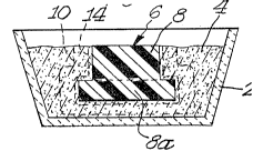
Referring now to the drawings, FIGURE 1 shows a
refractory vessel 2, such as an alumina vessel, containing a
bed of filler 4 which surrounds a pattern, indica~ed
generally by 6, of any suitable material such as polystyrene.
As shown in FIGURES 1 and 2, pattern 6 has a center section
8, which is generally cylindrical in configuration, joined by
an end section 8a which is axially shorter ~ut of greater
diameter than center section 8. In this embodiment, the
filler is retain~d by a suitable barrier means 10, such as a
stainless steel screen or perforated steel cylinder which
also establishes the boundaries of the ceramic body.
Alternatively, the barrier may comprise a plaster of paris
mold or calcium silicate mold typically applied as a slurry
to a substrate such as cardboard and then allowed to set.
The barrier thus defines the boundary or perimeter of the
ceramic body by inhibiting growth of the oxidation reaction
product therebeyond.
The pattern material 6, if foam, may be replaced by the
parent metal by pouring molten parent metal 12 directly onto
the pattern 6 in the cavity. In this way, the pattern
material is vaporized and exits the cavity either through the
bed of filler material, through the same port through which
the parent metal was added, or through a separate venting
port (not shown) if the port through which the parent metal
is added is relatively small.
.
1 307~ 1 3
19
In an alternative embodiment, the expendable pattern is
removed in a step prior to adding the molten parent metal.
This may be accomplished by melting the pattern and draining
the melted material from the cavity, but also can be
accomplished by placing the assembly in a furnace which is
heated to a point at which the expendable material is
vaporized or burned. As mentioned above, the pattern
material may also be removed by other techniques, such as
dissolving the pattern, mechanically removing the pattern,
etc.
After the parent metal is added to the caviky, the
assembly is heated to a temperature sufficient to melt the
metal, if it was not added in a molten state. Thereafter, a
sufficiently high temperature is maintained whereby a
vapor-phase oxidant, which permeates the bed of filler 4, and
is in contact with the molten metal, oxidizes the molten
metal, and growth of the oxidation reaction product resulting
therefrom infiltrates the surrounding bed of filler 4.
For example, when the parent metal is an aluminum
parent metal and air is the oxidant, the oxidation reaction
temperature may be from about 850aC to ahout 1450~C,
preferably ~rom about gO0C to about 1350C, and the oxidation
reaction product is typically alpha-alumina. The molten metal
migrates through the forming skin of oxidation reaction
product from the volume formerly occupied by pattern material
6, thereby forming the composite with a cavity replicating
the shape of the pattern.
In certain embodiments, it may be desirable to place a
quantity of the filler material over the port after the
parent metal is added to the cavity. A closed cavity would
thus be formed. In such embodiments, or even in some cases
without placing filler material over the port, the migration
of the parent metal can result in a pressure drop within that
' volume, as in the case of a closed cavity, due to
impermeability to the surrounding atmosphere of the growing
skin of oxidation reaction product in the bed of filler
material and the skin of oxidation reaction product forming
J-~ ~ on top of the pool of molten metal. Thus a net external
130~91~
pressure acts on the container-like skin of oxidation
reaction product. However, in a preferred embodiment the bed
of filler 4 (or a support zone thereof) enveloping pattern 6
is intrinsically self-bonding at or above a self-bonding
temperature which preferably lies close to but below the
oxidation reaction temperature. Thus, upon being heated to
its self-bonding temperature the filler, or a support zone
thereof, has sintered or otherwise bonded to itself and
attached to the growing oxidation reaction product
sufficiently to afford adequate strength to the filler
surrounding the developing cavity, i.e., the support zone of
filler, to resist the pressure differential and thereby
retain within the bed of filler 4 the geometry of the cavity
formed therein by conformance of the filler to the shape of
pattern 6. Representing an embodiment in which only a
support zone of filler 4 contains or comprises a sinterable
or self-bonding filler or a bonding or sintering agent,
dotted line 14 in FIGURE 1 indicates the extent of the
support zone in the bed of filler 4. As the reaction
continues, the cavity within bed 4 is partially or
substantially entirely evacuated by the migration of molten
parent metal through the oxidation reaction product to the
outer surface thereof where it contacts the vapor-phase
oxidant and is oxidized to form additional oxidation reaction
product. The oxidation reaction product comprises a
polycrystalline ceramic material which may contain inclusions
therein of unoxidized constituents of the molten parent
metal. Upon completion of the reaction, any remaining liquid
metal within the cavity may be eliminated by decanting it if
growth of a thick reaction product layer over the entry port
has been prevented (as by using a barrier or inhibitor).
Alternatively the assembly may be allowed to cool and any
excess metal solidified and removed in a subsequent step such
as acid leaching. The resultant ceramic composite, whose
dimensions are indicated by the barrier 10, in FIGURE 1, is
separated from exceæs filler, if any, left within vessel 2.
Such excess filler or part thereof may form a coherent mass
or body because of the sintering or self-bonding, and this
!
I 3079 1 3
21
coherent mass may be removed from the ceramic composite which
it encases by grit blasting, grinding, or the like. An
economical techni~ue is to employ grit blasting utilizing
grit particles of a material which is suitable as the filler
or as a component of the filler so that the removed Piller
and grit may be reused as filler in a subsequent operation.
It is important to recognize that the degree of strength of
the self-bonded filler used to prevent cavity collapse during
processing is typically much less than the strength of the
resulting composite. Hence, it is in fact quita feasible to
remove excess self-bonded filler by rapid grit blasting
without significant concern for damaging the resultant
composite. In any case, the ceramic composite structure
having the cavity formed therein may be further shaped by
machining or grinding or otherwise forming ~o a desired outer
shape. In the example illustrated in FIGURE 3, the ceramic
composite 18 has the shape of a circular cylinder having an
outer surface 20, end face 22 and cavity 24 which is defined
by surfaces congruent to the surfaces of pattern 6. Thus,
the shape of cavity 24 is an inverse replication of the shape
of expendable pattern 6. For many applications, the ceramic
body may be utilizable as formed following removal of the
excess, unentrained filler, without furthex re~uirement for
grinding or machining.
By selecting an appropriate filler and maintaining the
oxidation reaction conditions for a time sufficient to
evacuate substantially all the molten parent me~al from the
filled cavity initially occupied by the pattern material 6, a
faithful inverse replication of the geometry of pattern 6 is
attained by cavity 16. While the illustrated shape of
pattern 6 (and therefore of cavity 16) is relatively simple,
cavities can be formed within the ceramic composite which
inversely replicate with fidelity the shapes of much more
complex geometry than that of pattern 6 by the practices of
the present invention. The outer surfaces of the ceramic
composite may be shaped by placing a barrier means at the
desired locations to prevent growth there~eyond; in addition
the suEfaces may bé ground or machined or otherwise formed to
.
- 1307913
any desired size or shape consistent with the size and shape
of the cavity 16 formed therein~
It should be understood that the filler properties of
being permeable, conformable, and self-bonding (where
desired) as described above are properties of the overall
composition cf the filler, and that indi~idual components of
the filler need not have any or all of these characteristics.
Thus, the filler may comprise either a single material, a
mixture of particles of the same material but of different
mesh size, or mixtures of two or more materials. In the
latter case, some components of the filler may, for example,
not be sufficiently self-bondin~ or sintarable at the
oxidation reaction temperature but the filler of which it is
a component part will have the self-bonding or sintering
characteristics at and above its self-bonding temperature
because of the presence of other materials. A large number
of materials which make useful fillers in the ceramic
composite by imparting desired qualities to the composite
also will have the permeable, conformable and self-bonding
qualities described above. Such suitable materials will
remain unsintered or unbonded suf~iciently at temperatures
below the oxidation reaction temperature so that the filler
; which surrounds the pattern can accommodate thermal expansion
and any melting point volume change of the pattern material
and yet may sinter or otherwise self-bond only upon attaining
a self-bonding temperature which preferably lies close to and
below the oxidation reaction temperature, sufficiently to
impart the requisite mechanical strength to prevent collapse
of the forming cavity during the initial stages of growth or
development of the oxidation reaction product. Suitable
fillers include, for example, silica, silicon carbide,
alumina, zirconia, and combinations thereof.
As further embodiment of the invention and as explained
in the ~anadian Patents and Patent Applications and Patents,
the addition of dopant materials to the metal can favorably
influence the oxidation reaction process. The function or
functions of t:he dopant can depend upon a number of factors
other than the dopant material itself. These factors include,
.. ..
1307913
23
for example, the particular parent metal, the end product
desired, the particular combination of dopants when two or
more dopants are used, the concentration of the dopant, the
oxidizing environment, and the process conditions.
The dopant or dopants may be provided as alloying
constituents of the parent metal or may be applied to the
filler or to a part of thP filler bed, e.g., the support zone
of the filler, or both. In the case of the second technique,
where a dopant or dopants are applied to the filler, the
application may be accomplished in any suitable manner, sucn
as by dispersing the dopants throughout part of the entire
mass of filler as coatings or in particulate form, preferably
including at least a portion of the bed of filler adjacent
the parent metal. Application of any of the dopants to the
filler may also be accomplished by applying a layer of one or
more dopant materials to and within the bed, including any of
its internal openings, interstices, passageways, intervening
spaces, or the like, that render it permeable. A convenient
manner of applying any of the dopant material is to merely
soak the entire bed in a liquid source (e.g., a solution) of
dopant material. A source of the dopant may also be provided
by placing a rigid body of dopant in contact with and between
at least a portion of the expendable pattern surface and the
filler bed. For example, a thin sheet o~ silica-containing
glass (useful as a dopant for the oxidation of an aluminum
parent metal) can be placed upon a surface of the expendable
pattern. When the expendable pattern is raplaced by a
quantity of molten aluminum parent metal (which may also be
internally doped) and the resulting assemblage is heated in
an oxidizing environment (e.g. in the case of aluminum in
air, between about 850C to about 1450C, or preferably about
900C to about 1350C), growth of the polycrystalline ceramic
material into the permeable bed occurs. In the case where
the dopant lies between the parent metal and the bed of
filler material, the polycrystalline oxide structure
generally grows within the permeable filler substantially
beyond the dopant layer (i.e., to beyond the depth of the
applied dopant layer). In any case, one or more of tha
"'' ;
. ~,
,, - : .
..
1 307q 1 3
24
dopants may be externally applied to the expendable pattern
surface and/or to the permeable bed. Additionally, dopants
alloyed within the parent metal may be augmented by dopant(s)
applied to the filler bed. Thus, any concentration
deficiencies of the dopants alloyed within the parent metal
may be augmented by an additional concentration of the
respective dopant(s) applied to the bed, and vice versa.
Useful dopants for an aluminum parent metal,
particularly with air as the oxidant, include, for example,
magnesium and zinc, especially in combination with other
dopants as described below. These metals, or a suitable
source of the metals, may be alloyed into the aluminum-based
parent metal at concentrations for each of between about
0.1-10% by weight based on the total weight of the resulting
doped metal. The concentration for any one dopant will
depend on such factors as the combination of dopants and the
process temperature. Concentrations within the appropriate
range appear to initiate the ceramic growth, enhance metal
transport and favorably inEluence the growth morphology of
the resulting oxidation reaction product.
Other dopants whi.ch are effective in promoting
poly~rystalline oxidation reaction product growth, especially
for aluminum-based parent metal systems are, for example,
silicon, germanium, tin and lead, especially when used in
2~ combination with magnesium or zinc. One or more of these
other dopants, or a suitable source of them, is alloyed into
the aluminum parent metal system at concentrations for each
of from about 0.5 to about 15% by weight o~ the total alloy;
however, morè desirable growth kinetics and growth morphology
are obtained with dopant concentrations in the range of from
about 1-10% by weight of the total parent metal alloy. Lead
as a dopant is generally alloyed into the aluminum-based
parent metal at a temperature of at least 1000~C so as to
make allowances for its low solubility in aluminum; however,
the addition of other alloying components, such as tin, will
generally increase the solubility of lead and allow the
alloying material to be added at a lower temperature.
Additional examples of dopant materials useful with an
~ f
1 3079 1 3
aluminum parent metal includè sodium, lithium, calcium!
boron, phosphorous and yttrium which may be used individually
or in combination with one or more dopants depending on the
oxida~t and process conditions. Sodium and lithium may be
used in very small amounts in the parts per million range,
typically about 100-200 parts par million, and each may be
used alone or together, or in combination with other
dopant(s). Rare earth elements such as cerium, lanthanum,
praseodymium, neodymium and samarium are also useful dopants,
and herein again especially when used in combination with
other dopants.
As noted above, it is not necessary to alloy any dopant
material into the parent metal. For example, selectively
applying one or more dopant materials in a thin layer to
either all, or a portion of, the surface of the expendable
pattern enables local ceramic growth from the parent metal or
portion thereof and lends itself to growth of the
polycrystalline ceramic material into the permeable filler in
selected areas. Thus, growth of the polycrystalline ceramic
material into the permeable bed can be controlled by the
localized placement of the dopant material upon the sur~ace
of the expendable pattern. The applied coating or layer of
dopant is thin relative to the intended thickness of ceramic
composite, and growth or formation of the oxidation reaction
product into the permeable bed extends to substantially
beyond the dopant layer, i.e., to beyond the depth of the
applied dopant layer. Such layer of dopant material may be
applied by painting, dipping, silk screening, evaporating, or
otherwise applying the dopant material in liquid or paste
form, or by sputtering, or by simply depositing a laver of a
solid particulate dopant or a solid thin sheet or ~ilm of
dopant onto the surface of the expendable pattern. The
dopant material may, but need not, include either organic or
inorganic binders, vehicles, solvents, and/or thickeners.
More preferably, the dopant materials are applied as powders
to the surface of the expendable pattern or dispersed through
at least a portion of the filler. One particularly preferred
method of applying the dopants to the parent metal surface is
.~ ,.............................................................. .
-` 1 3079 1 3
to utilize a liquid suspension of the dopants in a
water/organic binder mixture sprayed onto an expendable
pattern surface in order to obtain an adherent coating which
facilitates handling of the expendable pattern prior to
processing.
The dopant materials when used externally are usually
applied to at least a portion of a swrface of the expendable
pattern metal as a uniform coating thereon. The quantity o~
dopant is effective over a wide range relative to the amount
of parent metal to be reacted, and, in the case of alumin~
experiments have failed to identify either upper or lower
operable limits. For example, when utilizing silicon in the
form of silicon dioxide externally applied as a dopant for an
aluminum magnesium parent metal using air or oxygen as the
oxidant, quantities as low as 0.00003 gram of silicon per
gram of parent metal, or about 0.0001 gram of silicon per
square centimeter of parent metal surface on which the sio2
dopant is applied, are effective. It also has been found
that a ceramic structure is achievable from an
aluminum-silicon parent metal using air or oxygen as the
oxidant by using MgO as a dopant in an amount greater than
about 0.0008 gram of Mg per gram of parent metal to be
oxidized and greater than about 0.003 gram of Mg per square
centimeter of parent metal surface upon which the MgO is
; 25 applied.
A barrier means may be used in conjunction with the
filler material to inhibit growth or development of the
oxidation reaction product beyond the barrier, especially
when vapor-phase oxidants are employed in the formation of
the ceramic body. Suitable barrier means may be any
material, compound, element, composition, or the like, which,
under the process conditions of this invention, maintains
some integrity, is not volatile, and preferably is permeable
to the vapor-phase oxidant while being capable o~ locally
inhibiting, poisoning, stopping, interfering with,
preventing, or the like, continued growth of oxidation
reaction product. Suitable barriers for use with aluminum
parent metal include calcium sulfate (Plaster of Paris),
.. ..,
,
1 3079 ~ 3
calcium silicate, and Portland cement, and mixtures thereof,
which typically are applied as a slurry or paste to the
surface of the filler materiaI. These barrier means also may
include a suitable combustible or volatile material that is
eliminated on heating, or a material which decomposes on
heating, in order to increase the porosity and permeability
of the barrier means. Still further, the barrier means may
include a suitable refractory particulate to reduce any
possible shrinkage or cracking which otherwise may occur
during the process. Such a particulate having substantially
the same coefficient of expansion as that of the filler bed
is especially desirable. For example, if the preform
comprises alumina and the resulting ceramic comprises
alumina, the barrier may be admixed with alumina particulate,
desirably having a mesh size of about 20-1000, but may be
still finer. Other suitable barriers include a stainless
steel screen, refractory ceramics or metal sheaths which are
open on at least one end or the walls perforated to permit a
vapor-phase oxidant (if used) to permeate the bed and contact
the molten parent metal.
The ceramic composita structures obtained by the
~ practice of the present invention will usually be a
; relatively dense, coherent mass wherein between about 5% and
about 98% by volums of the total volums of the composite
structure is comprised of one or more of the filler
components which are embedded within a polycrystalline
ceramic matrix. The polycrystalline ceramic matrix is
usually comprised of, when the parent metal is aluminum and
air or oxygen is the oxidant, about 60% to about 99% by
weight (of the weight of polycrystalline matrix) of
interconnected alpha-alumina and about 1% to 40~ by weight
(same basis) of non-oxidized metallic constituents, such as
from the parent metal.
The invention is further illustrated by the following
non-limiting examples.
Example 1
A styrofoam cup, about 7.5 cm long and having a base
',
- --` 1 307~ 1 3
28
diameter of about 4.5 cm and a wall thickness of 0.3 cm, was
coated with a mixture of 95~ silica and 5~ clay by applying a
water slurry of the silica and clay to the cup (just short of
the open end thereof) and heating to dryness. The coating
thickness was about the same as the wall thickness of the
cup. The coated cup was buried in a bed of loose
wollastonite with the end of the coating essentially flush
with the exposed surface of the bed.
The cup was filled with molten 380.1 aluminum alloy
(vaporizing the styrofoam) and the metal/bed assembly placed
in a hot furnace where it was heated at 1000C for 48 hours.
The resulting ceramic body was removed from the
wollastonite bed, the residual molten aluminum alloy
decanted, and the product allowed to cool, leaving a ceramic
cup having an internal surface which replicated in detail the
external surface of the styrofoam cup. The external surface
of the ceramic was defined by the wollastonite barrier
~ surrounding the original coated pattern. The wall of the
- ceramic cup was comprised of an alumina ceramic which had
grown through the thickness of the silica/clay coating.
Example 2
The procedure described in Example 1 was repeated with
the exception that alumina particles (Norton 38 Alundum of
70% 2~0 and 30% 500 mesh particle size3 was substituted ~or
the wollastonite, and the assembly was heated for 72 hours.
In this case, the alumina matrix grew through the thickness
of the silica/clay coating and, into the surrounding alumina
particles, forming a wall measuring up to about 0.6 cm.
Again the internal surface of the ceramic composite
replicated the external surface of the styro~oam cup pattern.
Although only a few exemplary embodiments of the
invention have been described in detail above, those skilled
in the art wi:Ll readily appreciate that the present invention
embraces many combinations and variation other than those
exemplified.
~,
.~