Note: Descriptions are shown in the official language in which they were submitted.
~ ~3~342
OPTIC~L RADIATIO~ SE~SOR ~PP~B~TUS t
Back~round of the Invention
This invention relates to optical radiation sensor apparatus.
The invention is more especially, but not exclusively, ~oncerned with
optical pyrometer apparatus.
Optical pyrometer apparatus are used for measuring high temperatures in
for example, gas-turbine engines and furnaces. The pyrometer apparatus
includes a radiation receiving head, a radiation detector which produces an
electrical output, a preamplifer for amplifying the detector output, and
utilising apparatus for scaling, comparison and calculation on the
preamplified output of the detector to provide an output suitable for display
of temperature, data storage, performance o~ a control function and so on.
The radiation dete~tor may be contained in the receiving head 80 that an
electrical output is produced, but there are advantagQs to mounting the
detector remotely snd interconnecting the detector and receiving head by a
flexible radiation guide, such as a fibre-optic cable. In this way9 the
detector can be mounted at a cooler location. Such fibre-optic pyrometers9
therefore comprise three separate units: the pyrometer head; the detector and
preamplifier or other signal conditioning unit; and the ~tilising apparatusO
The pyrometer head is connected to the detector by a fibre-optic cable: the
detector i9 connected to the utilisation apparatus by an electrical cable.
Other similar optical radiation sensor apparatus are also divided into three
units interconnected by cables.
~3~79~;2
Such apparatus has several disadvantages. The electrical cable and
connectors between the detector and utilisation apparatus adds to the overall
weight of the pyrometer, especially where the cable is screened which is
usually necessary in aircraft applications. The cable and connectors can also
be susceptible to electromagnetic interference. The detector must also be
clamped, screwed or otherwised secured in place, making installation more
difficult.
Brief Summary of the Invention
It is an object of the present invention to provide optical radiation
sensor apparatus with advantages over previous apparatusO
According to one aspect of the present invention there is provided
optical radiation sensor apparatus comprising an optical radiation receiving
head arranged to receive radiation; optical radiation guide means having one
end coupled with the receiving head, said guide means being arranged to
transmit radiation from the receiving head; optical detector assembly
including a first rigid casing enclosing an optical radiation detector device
and electrical signal conditioning means having an input connected with the
detector device and an output connected with a first mateable connector device
on said casing; and a processing unit including a second rigid cas;ng
containing electrical circuit means having an input connected with a second
mateable connector device on the second casing, said cir6uit means being
arranged to process the output of the detector assembly, said second connector
device being adapted to mate and engage directly with the first connector
device such that the optical detector assembly can be connected with the
~L3~79~2
processing unit without the interposition of any cable between the respective
casings.
The detector assembly is preferably retained on the processing unit
substantially solely by mating of the first and second connector devices. The
first rigid casing may be of substantially cylindrical shape. The first
mateable connector device may be secured wîth the first casing by means of
cooperating screw threads on the connector device and casing. The electrical
signal conditioning means preferably includes amplifier means arranged to
amplify the output of the detector device. The guide means may include an
optical fibre cable. The receiving head may include converging lens means
arranged to focus radiation onto an end of the optical fibre cable and the
detector device may include a photodiode.
The first and second connector devices are preferably arranged to be in
good therm&l contact with one another when mated such as to promote
equalisation of the temperatures of the first and second casings. The first
connector device may be provided with an annular flange that is arranged to
contact a surface on the second connector device so as to provide good thermal
contact between the two connector devices. Thermal transfer means may be
associated with the second casing and the thermal transfer means may be
supplied with a cooling fluid such as liquid fuel. The optical radiation
detector device may be thermally insulated from the first casing. The
processing unit may be arranged to receive input signals-from other sources.
The apparatus may be a pyrometer and the output of the processing unit
may be supplied to an engine control unit.
. ~
~3~7~4;2
Pyrometer apparatus for a gas-turbine engine in accordance with the
present invention will now be described, by way of example, with reference to
the accompanying drawings.
Brief-Descri~tion of the Dra~in.s
Figure 1 illustrates the pyrometer apparatus
installed on a gas-turbine engine;
Figure 2 is a sectional view of a part of the
apparatus; and
Figure 3 shows the electronic components of the
apparatus schematically.
'
~L 3~ 7 ~ d9
Detailed Description
With reference first to Figure 1, the pyrometer apparatus comprises a
pyrometer head 1, mounted to view the blades 2 of a gas-turbine engine, a
detector 3 connected with the pyrometer head by means of a cable 4, and a
processing unit 5 which receives the detector output and provides a signal
related to temperature and other parameters to an engine control unit 6.
:
The pyrometer head 1 is of conventional construction, such as described
in GB 2158576A or GB 1589531, having a heat-resistant converging lens 10
mounted towards the rear of a sighting tube 11. The lens 10 focuses radiation
10 emitted by the blades 2, which enters the sighting tube 11, onto the forward
end 40 of the cable 4. The cable 4 is a fibre-optic cable, or some similar
optical radiation guide, and is fle~cible or bendable so that there is freedom
in the mounting of the pyrometer head 1 and detector 3. The cable 4 may be
armoured for protection and is long enough to enable the detector 3, at the
15 rear end 41 of the cable, to be located at a cooler region.
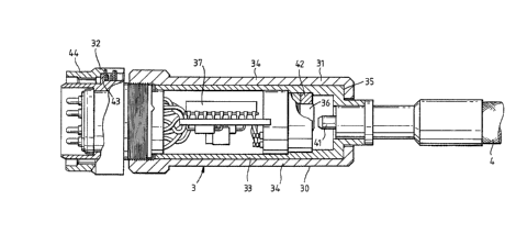
With referance now to Figure 2, the detector has a cylindrial casing 30
formed by a forward part 31 and rear connector or plug assembly 32. The
forward part 31 comprises an inner sleeve 33 welded to the rear end of the
cable termination 41, and an outer sleeve 34, the forward end of which engages
20 a shoulder 35 on the inner sleeve and the rear end of which is joined to the
plug assembly 32. The overall length of the detector 3 is 60mm and it has a
diameter of 20mm. Within the forward part 31 of the detector 3 there are
mounted one or more photodiodes 36 which receive radiation emitted from the
rear end termination 41 of the cable 4. The photodiode 36 is supported in
25 the inner sleve 33 by a heat insulating support ring 42. A self-regulating
heating element (not shown) may be mounted close to the photodiode to enable
its temperaturP to be raised when necessary.
~L3(~7~
.
The electrical output of the photodiode 36 is supplied to an electrical
circuit assembly 37 within ehe casing 30 which is shown in greater de~ail in
Figure 3.
The circuit assembly 37 includes an amplifier 38 which produces a
S voltage output proportional to the current output of the photodiode 36. This
voltage is amplified at a gain stage 39. A circuit 50 may be included for
removing signals produced by extraneous fl~mes within the engine. In general,
the circuit assembly 37 produces electrical signal conditioning of the output
of the photodiode 36 into a form suitable for handling by the processing unit
5. The signals at the output of the circuit assembly 37 are supplied via
lines 51 to the plug assembly 32 formed at the rear end of the detector casing
30. The plug assembly 32 is a multi-pin plug-in mateable connector and
includes pins by which electrical power is supplied to the circuit assembly
37. The plug assembly 32 has a radially extending flange 43 that is embraced
by an outer, threaded locking ring 44.
The plug assembly 32 on the detector 3 is arranged to mate directly with
a cooperating connector 52 on the casing 53 of the processing unit 5. The
connector 52 has a flat surface (not shown) against which the flange 43 on the
connector 32 is abutted in good thermal contact~ The processing unit 5
contains electronic processing circuits, indicated generally by the numeral
54. These circuits are connected to the connector 52 so as to receive the
signal conditioned output of the photodiode 36 in the detector 3. The
processing unit also receives inputs on lines 56 from various other sensors
and control devices indicative of, for example, speed, temperature and
pressure, and provides an output to the engine control unit 6. The processing
unit 5 includes a thermal transfer unit 60 mounted on its casing 53 which is
~ ' `.
~3~79~;~
.
supplied with a fluid, such as liquid fuel, to effect heat transfer, and, more
particularly, cooling of the processing unit 5.
One typical method of measuring temperature~involves comparing the
radiation levels at two different wavelengths. In such an arrangement, the
detector would include two photodiodes responsive to the respective two
wavelengths. The two outputs produced may either be compared by circuitry in
the detector 3 itself, or in the processing unit 5.
,
The output of the processing unit 5 is supplied by a cable 57 to the
engine control unit 6 which provides control of various engine functions. The
output of the processing unit 5 may additionally, or alternatively, be
supplied to some other form of utilisation means 6' such as, for example, a
data recorder or a display.
The arrangement of the present invention, by having a connector 32 on
the casing of the detector 3 that is directly mateable with a connector 52 on
the casing 53 of the processing unit 5, without the interposition of any cable
between the two casings, leads to a very compact arrangement and is less
susceptible to electrical noise and other electromagnetic interference. By
avoiding the need for a cable between the casings of the detector and
processing unit, the overall weight of the apparatus can be kept to a minimum.
The detector is directly mounted on the processing unit thereby facilitating
installation and maintenance. In this respect, the mating connectors on the
detector and processing unit may be loc~ing connectors which are sufficient in
themselves to support the detector 3.
~36~9~2
Because the mating connectors 32 and 52 are in good thermal contact, via
the flange 43, any external heating of the detector 3 can be dissipated
efficiently via the casing 53 o the processing unit 5 and the thermal
transfer unit 60. This reduces the risk of overheating the photodiode 36
which is further reduced by the heat insulating ring 42. Where the apparatus
is used in an environment that is below the optimum temperature of the
photodiode 36,the thermal transfer unit 60 can be used to raise the
temperature of the detector 3, and the heating element (not s~own) used to
raise the temperature of the photodiode 36 directly.
In severe temperature environments, the temperature of the detector 3
can be maintaned more stable by means of a protective shroud around the
detector, separated from the outer sleeve 34 by an air gap. This is
especially effective where the detecto~ is located in a stream of flowing gas
at e~treme temperature.