Note: Descriptions are shown in the official language in which they were submitted.
1 308078
ARRANGEMENT FOR THE SUPPLY AND
METERED DISPENSING OF LIQUIDS
The present invention relates to an arrangement for
the storing and metered dispensing of liquids, in
particular beverage concentrates, by means of a storage
vessel for liquids, at the dispensing opening of which,
located at the bottom when in the operating position,
there is positioned a dosing chamber/dispensing fixture
having input- and output-side discharge openings that
can be closed alternately by a sliding control valve
displaceable in the dosing-chamber housing.
As an example, these arrangements are preferably
used in beverage dispensers, by means of which
carbonated water is mixed with beverage concentrates for
a refreshment drink. Storage vessels for the beverage
concentrates are usually fabricated from a dimensionally
stable and gas-tight material, and are shaped like a
bottle or cuboid. When installed in a beverage
dispenser, these storage vessels are positioned with
their discharge opening downward. Attached to this
discharge opening is a dosing chamber/dispensing fixture
with input- and output-side discharge openings that can
be closed alternately by means of a sliding control
~'
'
~,
,:
" ~,- ; ~
- ' !
~ . ' , .
1 308078
valve. The liquid (beverage concentrate) flows by gravity
from the storage vessel into the dosing chamber~dispensing
fixture, when that fixture's input-side discharge opening is
opened. When this input-side discharge opening is closea by
the sliding control valve and, at the same time, the output-
side discharge opening is opened, the liquid -- likewise by
gravity -- emerges from the dosing system, so that the quan-
tity of liquid is essentially determined by the dosing-cham-
ber capacity.
In the prior art dosing chamber/dispensing fix-
ture.s, however, leakage flows between the sliding control
valve and the dosing-chamber housing can influence the
quantity dispensed in a manner difficult to control. Design
of a guideway between the slidirg control valve and the dos-
ing-housing, which is as free of gaps as possible to avoid
these leakage flows, is highly problematical, since this
sliding control valve is supposed to be axially movable with
the greatest possible ease inside the dosing-chamber hous-
ing, so it can be reliably adjusted, in the form of a
solenoid plunger, by an electrically generated magnetic
field. This method of adjustment requires no mechanical
linkages, so that replacement of the dosing chamber/dispens-
ing fixtures in the beverage dispenser, together with the
storage vessels~ can be carried cut with ease.
'
--
~ I ,
1 308078
It is possible to ventilate the head room of this
storage vessel or a buffer space therewithin (DE OS 25 44
671) in order to ensure that the flow of liquid is not
hampered by volume-equalizing air counterflows and by the
subatmospheric pressure developing. These measures require
additional technical effort, yet they have not proven to be
advantageous, since the air in the head room of the storage
vessel easily escapes therefrom to enter the head room of
the storage vessel during the flow of the liquid. In the
prior art systems, it has even been found expedient to
cause a build-up o~ subatmospheric pressure in the head room
so as to counteract the leakage flows between the dosing
plunger and the wall of the dosing-chamber housing.
Also, for reasons having to do with transport and
for ease of handling, it has proven very advantageous to
make the storage vessel for beverage concentrates of a
material that is dimensionally stable. However, such
storage vessels are relatively expensive and troublesome
with respect to waste disposal, the more so since the
vessels can be used only once and are then discarded. The
convenience of using the storage vessel only once is based
on reasons of hygiene, but also because of steps taken to
prevent the use of a refilled storage vessel. Precautionary
- : :
!.
'~' ;
1 308078
steps are taken by adopting appropriate measures in the area
of the dispensing opening of the storage vessel.
Accordingly, the aim of the invention is to reduce the
production cost particularly for these storage vessel~ and
to overcome the waste disposal problems thereof without
impairing their ease of handling. The arrangement for the
storing and metered dispensing of li~uids is also to be
improved in terms of reliability.
Various aspects of the invention are as follows:
An apparatus for the metered dispensing of beverage
concentrates from a storage container having a discharge
opening located in the bottom of the contain~r when in a
dispensing position, comprising: a dosing chamber assembly
including a chamber housing having only two openings
including an input opening including an input opening
communicating with the discharge opening of the container
and an output opening, whereby the chamber housing defines a
predetermined volume for metering a beverage concentrate;
a sliding control valve displaceable in the chamber housing
of said dosing chamber assembly to alternately open and close
the input and output opening of the chamber housing, wherein
said input opening of said chamber housing is disposed at the
top thereof concentric with the longitudinal axis thereof,
and said sliding control valve includes a tubular slide
opening and a disc which seals off the entire chamber housing
from the interior of said bag when said input opening is
closed thereby, and guide ribs extending upwardly from said
disc into the input opening of said chamber housing, said
guide ribs slidably engaging walls of said input opening;
said container including a gas-impermeable and substantially
flexible bag disposed within a substantially dimensionally
stable outer shell; and socket means having a first open end
coupled to both said bag and said shell and a second open end
for receiving said dosing chamber assembly.
.
1 3408078
An apparatus for the metered dispensing of beverage
concentrates from a storage container having a discharge
opening located in the bottom of the container when in a
dispensing position, comprising: a dosing chamber assembly
having a chamber housing having only two openings including
an input opening communicating with the discharge opening of
the container and an output opening, whereby the chamber
housing defines a predetermined volume for metering a
beverage concentrate; a sliding control valve displa~eable
in the chamber housing of said dosing chamber assembly to
alternately open and close the input and output openings of
the chamber housing thereby metering an amount of beverage
concentrate, wherein said sliding control valve includes a
disc, and guide ribs extending upwardly from said disc into
the input opening and said disc selectively sealing said
input opening; said container including a gas-impermeable
and substantially flexible foil bag disposed within a
substantially dimensionally stable outer shell; and
socket means having a first open end coupled to both said
bag and said shell and a second open end for receiving said
dosing chamber assembly.
By way of added explanation, an arrangement which
satisfies these requirements is characterized, in accordance
with the invention, by forming the storage vessel from a
gas-impermeable and essentially flexible foil bag and an
essentially dimensionally stable, air-permeable vessel wall
which surrounds the flexible foil bag in cuboidal
configuration, and by attaching the flexible film bag and the
essentially dimensionally stable vessel wall to a connecting
pipe socket forming the dispensing opening and with which the
dosing chamber/dispensing fixture can be connected.
Preferably, this vessel wall is made of fiberboard carton and
in a box-type configuration.
A storage vessel constructed according to these novel
Peatures is distinguished by the fact that the flexible and
gas-impermeable foil bag, which can be made
~ 308078
of inexpensive material, e.g., an aluminum-clad foil, pro-
vides adequate protection against the environment for the
liquid contained therein, especially for beverage concen-
trate, and that the essentially dimensionally stable stor-
age wall, which can be made of a cheaper material, e.g.,
fiberboard carton, provides adequate protection against
mechanical damage of this foil bag and also affords the
possibility of ease of handling of the storage vessel. In
particular, from the viewpoint of production engineering, it
is advantageous to indirectly attach the dimensionally
stable storage wall to the connecting pipe socket of the
storage vessel by means of the foil bag. By linking the
connecting pipe socket to the essentially aimensionally
stable storage wall, the entire storage vessel can be given
the strength needed for a trouble-free mounting and attach-
ment of a dosing chamber/dispensing fixture to the connect-
ing pipe socket of the storage vessel.
In order, on the one hand, to afford the possibi-
llty of carrying out the volume metering by means of the
dosing chamber/dispensing fixture in accordance with the
nature of the liquid stored in the storage vessel and, on
the other hand, to provide protection against improper use
of the storage vessel, it is advantageous to integrate a
part of the dosing chamber/dispensing fixture, namely the
1 308078
input-side area, into the connecting pipe socket of the
storage vessel through the discharge opening that can be
closed by the regulator piston. This area is so designed
that, once connected to the main parts of the dosing
chamber/dispensing fixture, it is no longer usable.
Before connecting these dosing chamber components, the
dispensing opening of the connecting pipe socket is
firmly closed with a foil cover.
If the flexible foil bag is not bonded to the di-
mensionally stable vessel wall, the problem arises thatno well-defined pressure difference relative to the
outside atmosphere can develop in the storage vessel.
This makes it difficult to use the prior art dosing
chamber/dispensing fixtures, since the leakage flow of
the liquid to be metered by these known dispensers
cannot be prevented by the subatmospheric pressure in
the storage vessel.
For this reason, it is advisable to provide the
arrangement for the storing and metered dispensing of
liquids with a dosing chamber/dispensing fixture in
which a tubular sliding control valve, arranged to be
movable in longitudinal direction, with a solenoid
plunger of a solenoid plunger/electromagnet system, said
solenoid plunger being integrated into the tube wall,
and which is characterized by the fact that the
input-side discharge opening is
.~
, :.
.
. :~
1 308078
placed in the center of the dosing chamber/dispensing fix-
ture in the head room of said closing chamber/dispensing
fixture, and that opposite this discharge opening on the
tubular control valve there is positioned a valve-closing
disc, by means of which the discharge opening can be closed
in lid fashion, in the direction of-movement of the sliding
control valve, against the whole interior of the dosing
chamber housing. By using this technique, it is practically
certain that liquid from the storage vessel will continue to
flow across uncontrollable leakage flows. The pressure in
the storage vessel will no longer have any effect whatever
on the quantity of liquid being dispensed. The dispensed
liquid depends solely on the actual volume defined by the
housing of the dosing chamber.
Often it is necessary, or only useful, to cool
vessels for beverage concentrates ir. a beverage dispenser.
As a rule, the cooling phases occur intermittently. The
temperature in the storage vessel fluctuates during the
intermittent cooling phases contingent upon the measuring
and cooling technologies. This can cause pressure fluctua-
tions in storage vessels designed with dimensional stabili-
ty . By using flexible foil bags for receiving the liquids
dispensed in measured portions, volume equalization is pro-
vided to prevent significant variations of the inner press-
:~ '' ~ .
.
` :,
1 308078
ure in the storage vessel. However, the special design ofthe proportioning chamber/dispensing fixture with the input-
side discharge opening located in the center o~ the head
room and closable in lid fashion by the valve-sealing disc
of the sliding control valve also makes certain that the
pressure differences within the storage vessel will not have
any effect on the metered quantities.
According to a preferred emboaiment, the dosing
chamber/dispensing fixture of the arrangement incorporating
the invention is characterizea by the mounting, on the
valve-sealing disc, of guide ribs that project into the
input-side discharge opening of this dosing chamber/dis-
pensing fixture. This lengthens in an axial direction the
guideway for the sliding control valve to the input-side
discharge opening of the dosing chamber/dispensing fixture.
According to another preferred emboaiment, longi-
tudinally directed guide ribs are mounted between the outer
jacket of the tubular sliding control valve and Ihe cylin-
drical wall of the dosing chamber/dispensing fixture.
Thereby, the gap between the sliding control valve and the
wall of the dosing-chamber housing can be enlarged suffi-
ciently without the risk of tipping the sliding control
valve in the dosing chamber, thereby reducing the friction
between this sllding control valve and the ~osin~-chamber
.
- . .
..;
: - ,. ,:
:.
"` 1 30~078
housing. From the production viewpoint, it is advantageous
to install the longitudinally directed guide ribs on the
outer jacket of the tubular sliding control valve.
It is desirable that the main components of the
dosing chamber/dispensing fixture be standardized and that
the working stroke of the sliding control valve be made of
uniform length as well. This step is of great importance for
use in beverage dispensers, in which a magnetic flux gene-
rated by an electromagnet system in the apparatus housing.
controls the sliding control valve actuated as a solenoid
plunger. By standardizing the components and mkaing the
working strokes of uniform length, the magnetic flux to be
generated can be standardized as well. Nevertheless, there
must be an option to meter differing quantities of liquids
on account of the different natures natures of the liquids
to be metered, namely, the different beverage concentrates.
Depending on the particular type of beverage concentrates
used, different mixing ratios are required with the other
component, namely, the carbonated water.
To obtain these differing metered quantities, and
nevertheless to be able to fall back on a dosing system that
is as unitized as possible, it is advisable, within the
scope of the invention, to design the system in such a way
that the input-side discharge opening lie in a dosing-
,
;.:~ , .
1 30807~
chamber cover detachably fixed to the dosingchamber/dispensing fixture with side walls that surround
the inner volume. Without requiring the stroke range of
the sliding control valve to be changed, the inner
volume of the whole dosing chamber/dispensing fixture
can be variably and properly adjusted according to the
concentrate used by appropriately expanding or
contracting shapes of these side-wall areas. If the
housing cover of the dosing chamber/dispensing fixture
is structurally integrated into the connecting pipe
socket of the vessel for liquids, a direct relationship
is achieved between the kind of beverage concentrate and
the metered quantity.
Details of the design incorporating the invention
will now be described, reference being had to the
practical embodiment shown in the drawing, in which:
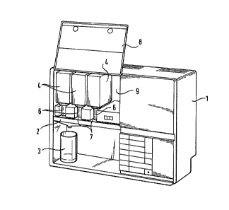
- Figure l is a perspective view of a beverage
dispenser with storage vessels for beverage
concentrates;
- Figure 2 and
- Figure 3 are perspective views of storage vessels
for liquids with and without a dosing
chamber/dispensing fixture;
: ' `
'
.
11 1 308078
- Figure 4 is a sectional elevational view of a
storage vessel for beverage concentrates with a
dosing chamber/dispensing fixture attached thereto;
- Figure 5 and
- Figure 6 are various designs of input-side
housing covers for the dosing chamber/dispensing
fixture.
The beverage dispenser depicted in Figure 1 serves
: to mix water, stored in the apparatus housing, enriched
with CO2 gas and cooled, with a beverage concentrate
within a mixing trough 2, and to dispense the resulting
refreshment drink into a drinking vessel 3. To enable
production of different sorts of refreshment drinks, in
the present instance three types of beverage
lS concentrates are stored in three storage vessels 4
installed in the beverage dispenser above the mixing
trough 2, such that the dispensing openings are directed
downwards. On a connecting pipe socket 5, each of these
storage vessels 4 is assigned a dispensing opening of a
dosing chamber/dispensing fixture 6. This dosing
chamber/dispensing fixture contains a sliding control
valve provided with a ferromagnetic armature. In the
housing 1 are installed electromagnets which can
generate a magnetic field in the area of the locating
slot 7 for the dosing chamber/dispensing fixture 6,
through which the sliding control valve is influenced
inside the dosing chamber/dispensing fixture. Thereby, a
.~
,
12 l 308078
metered serving of beverage concentrate is fed to the
mixing trough 2, in which the mixing process takes
place, with carbonated water likewise metered into the
mixing trough 2. The housing chamber 9 which can be
closed with a cover 8 and in which the storage vessels 4
are accommodated, is connected to the refrigerating
circuit of a refrigerating plant, so that the beverage
concentrates are stored chilled and thus stand ready for
the mixed drink.
Figure 2 shows a storage vessel 4 for liquid con-
centrates as it is transported from filler to user. The
dispensing opening in the connecting pipe socket 5 is
sealed by a foil cover lO. Figure 3 shows a storage
vessel 4 for a beverage concentrate with the dosing
lS chamber/dispensing fixture mounted on the connecting
pipe socket 5.
The storage vessels 4 and details of the dosing
chamber/dispensing fixture for beverage concentrates are
apparent from the cutaway view shown in Figure 4. The
storage vessel 4 consists of a foil bag 11 with
substantially flexible walls. These walls of the foil
bag 11 are firmly attached in annular configuration to
the connecting pipe socket 5 of the storage vessel 4.
This foil bag is surrounded by essentially dimensionally
stable, air-permeable vessel walls 14 in a cuboidal
configuration as shown
.
-` 1 308078
in ~igures 2 and 3. The material for the vessel walls 12 is
preferably fiber-board carton. These walls 12 form a unit
and are likewise attached to the connecting pipe socket 5 of
the storage vessel 4 via the walls of the foil bag 11.
The dosing chamber/dispensing fixture 6 is formed
by an input-side dosing-chamber housing 14 widened out with
a housing cover 13 and in which is mounted a tubular sliding
control valve 15, which is vertically adjustable.
The housing cover 13 is a component of the con-
necting pipe socket 5 of the storage vessel 4 integrated
into the mounting system. The housing 14 of the dosing
chamber/dispensing fixture is attached to the housing cover
13 by short screw threads 29 dist~ibuted along the circum-
ference and sealed by a packing plate 16 against this hous-
ing cover 13. The seal ring 17 is provided for sealing
against the outside atmosphere because, for production
engineering reasons, openings 18 are provided in the upper
closure wall of the housing cover 13 for cutting the screw
threads 29.
In the dosing chamber/dispensing fixture 6 with
the substantially rotationally symmetrical design, the in-
: put-side discharge opening 19 is arranged axially central in
: the housing cover 13 and the output-side discharge opening
'.
-` 1 308078
14
20 at the lower end o~ the dosing-chamber housing 14. Oppo-
site these discharge openings 19 and 20, there are supported
on the sliding control valve 15 valve-sealing di_cs 21 and
22, which alternately close the input-side discharge opening
l9 or -- as shown in Figure 4 -- the output-side discharge
opening 20, depending on the vertical end position of the
sliding control valve 14. The sliding control valve 15 has a
substantially tubular form and supports an input-side valve-
sealing disc 21 in a cylindrical attachment 23 with holes
24. There project above this valve-sealing disc 21 cross-
shaped guide ribs 25 as guiding elements into the input-side
discharge opening 19. The sliding control valve 15 has a
ring 26 of ferromagnetic material which, as a solenoid
plunger inside an electromagnet system installed in the
apparatus housing, is influenced by induction of a mag-
netic field such that the sliding control valve is lifted
off the position shown, in which the output-side discharge
opening 20 is closed, to the upper position, in which the
input-side discharge opening 19 is closed. On the peripheral
surface of the sliding control valve 15 there are arranged
longitudinally extending guide ribs 27, so that good anti-
~riction properties are provided batween the sliding control
valve 15 and the wall of the dosing-chamber housing 14.
1 308078
In the position of the sliding control valve 15
shown in Figure 4, beverage concentrate stored in storage
vessel 4 can flow into the interior of the dosing chamber/
dispensing fixture 6 through the input-side discharge
opening 19, due to its own gravity. The air volume present
in the dosing chamber/dispensing fixture 6 flows into the
storage vessel 4. Due to the fact that this inflowing air
is originally hotter than the normally cooled beverage con-
centrate being dispensed, a volume deficit develops after
this air is cooled. Since the wall 11 of the foil bag is
flexible and the dimensionally stable wall does not seal
this foil bag hermetically, this volume deficit is taken
care off even by slightly bagging this foil bag, so that
there is no subatmospheric pressure in the storage vessel 4.
Likewise, due to the flexibility of the foil bag 11, tempe-
rature differences, and thereby volume changes in the stor-
age vessel 4, are equalized by intermittent cooling proces-
ses.
By creating a magnetic field with an electromagnet
system installed in the apparatus housing 4, a lifting power
is exerted on the ferromagnetic ring 26 of the sliding con-
trol valve 15. Qs a result, the input-side discharge opening
19 is closed by the valve-sealing disc 21, so that no more
beverage concentrate can get to the dosing chamber/dispens-
,. .
. :
:
.
1 3080-~8
16
ing fixture 6 from the storage vessel 4, while the output-
side discharge opening 20 is openea and the quantity of
beverage concentrate found originally in the dosing
chamber/dispensing fixture 6 can emerge. Again, the volume
flowing out is replaced by air in the dosing chamber/dis-
pensing/dispensing ~ixture 6. By means of this dosing
chamber/dispensing fixture 6, a high degree of accuracy is
achieved in the dispensed volume. This accuracy is of the
greatest importance in achieving an optimum mixture ratio
with the carbonated water which is also introduced in mea-
sured portions into the mixing trough 2.
Different beverage concentrates require different
dosing quantities. In order to meet this requirement, with
a dosing chamber/dispensing device which is unitized with
the essential structural parts, the technical effort for
producing the different variants is reduced to the different
shapes of the side walls 28 of the housing cover 13. Figure
5 shows the same housing cover 13 as in Figure 4, while
Figure 6 shows a housing cover 13' with beveled walls 28',
which taper off toward the discharge opening 19'. Thus,
compared to the use of the housing cover 13 shown in Figure
5, if the housing cover 13' is constructed as in Figure 6, a
volume change will result in this area and, thereby, for the
whole dosing chamber/di:pensine iixture 6. Since these
.
,~
: ::
17 l 30807~
housing covers 13 or 13' are integrated into the
connecting pipe socket 5 of the vessel 4, a direct
relationship is achieved with respect to the nature of
the beverage concentrate used. Further volume reduction
in the dosing chamber/dispening fixture 6 is possible by
introducing an additional pipe inlet into the regulator
plunger.
After removal of the dosing-chamber housing 14 from
the housing cover, rupture joints 30 serve to separate
the housing cover from its flange 31, thus rendering it
unreliable for further coupling.
The invention being thus described, it will be
obvious that the same may be varied in many ways. Such
variations are not to be regarded as a departure from
the spirit and scope of the invention, and all such
modifications as would be obvious to one skilled in the
art are intended to be included within the scope of the
following claims.
2~
`'
'
~,
.~ '
.:
;. : . :
. . .
.. .. .
. :
,,
.