Note: Descriptions are shown in the official language in which they were submitted.
07MS1487/1330r 785-87-0020
, . ~ --1--
1 3080qO
EI~3Cl~RIC~LLY ACTUAT33D E&~ V~LVE
Backgrou~d and ~ n~mAry of Invention:
This invention relate~ generally to e~hau~t gas recirculation (EGR)
valve~ a~d more ~3pecifically to such valve~ which are electncally
5 actuated.
An exhau~t gas recirculation valve i~ common place in the pollution
con*ol sy~tem of automotive engines. The EGR valve recirculates a
predetermined amount of exhau~t gas from the e2~hau t system to the
lo intake mani~old. Prior EGR valves relied upon vacuum motors for
actuation. Such vacuum actuation provided for the continuous
movement of an armature or closure member relative to a valve seat. A
deficiency in the vacuum operated EC~R valves i~ that ~ufficient vacuum
force i~ not alwa;ys available during needed period~ of operation. Later
5 versions of l3GR valves contemplated replacing the vacunm motor with a
variety of electrical actuatore ~uch as a stepper motor. A goal of
electroDically controlled EGR valves iB to meet the continuous
performance characteristics of the vacuum actuated valves. As euch, a
~tepper motor having many pole3 i~ used to appro~nate the resolution
20 of the vacuum activated EGR's, however, the increased number of poles
increases the cost of the device. Another inhere~t shortcoming of the
stepper motor or of a DC motor controlled EGR valve i3 in its failsafe
mode of operatio~. It i~ de~irable that upon electroDic failure, the EGR
valve should remain clo~ed. Ihi~ i~ difficult to achieve in the ~tepper or
25 DC motor EGR valve since the position of the closure element is often
e~tabli~hed by a lead screw and nut which i~ driven by the motor and as
such, the lead screw and nut may rest in an intermediate po~ition at the
time of failure of the motor. Another variety of electric~lly operated
EGR valve i~ that type of valve which utilize~ solenoida To achieve
. .
- .. . .
,. .
07MS2487/1330r 1 3 0 ~ ~ q ~ 785-87-0020
~ -- 2 --
adequate resolution can require using a plurality of such
solenoids which increases the complexity and cost of the system.
Typically the solenoid controlled EGR valve is constructed such
that in the absence of an electrical signal a spring biases the
closure member against a valve seat. As such, the closure element
is maintained at its largest air gap. The solenoid can only
provide the minimum available force when the closure member is
against the valve seat and therefore it cannot precisely control
the flow rate through the EGR valve when it is most crucially
needed. Further, linear solenoids have a greater out of balance
force resulting from a relatively heavy armature supported against
a spring. Consequently, the linear armature is more difficult to
control when subjected to high vibrational forces.
It is an object of the present invention to provide an EGR valve
having high resolution at smaller valve openings than at larger
valve openings. A further object of the present invention is to
provide precise EGR control at low engine speeds. A further
ob~ect of the present invention is to provide an EGR valve that is
controllable in a position measurement and in a differential
pressure mode of operation.
Accordingly, the invention comprises a valve comprising a valve
seat positioned about a passage; a rigid valve stem that is
movable in a substantially axial manner relative to the valve seat
from a first position corresponding to a valve seat closure to a
second position corresponding to a non-closure of the valve seat;
closure means carried by the valve stem for seating upon the valve
seat and for opening and closing the passage; an eccentric that
can execute arcuate motion about an axis and comprises, in spaced
relation to the axis, a pivotal connection to the stem; a valve
stem guide that is spaced from the valve seat and from ~he pivotal
connection of the ecceDtric to the stem; the valve stem guide
comprising a convex wall defining a valve stem passage
07MS1487/1330r 1 3 0 ~ 0 9 0 785-87-0020
" - 2a -
through which the valve stem extends and which is substantially
coaxial with the first-mentioned passage, the convex wall
providing a constraint on the valve stem passage as the stem is
being axially displaced through the valve stem passage; the
eccentric and the convex wall being organized and arranged in
relation to the stem such that in response to arcuate motion of
the eccentric about the axis from a first angular orientation,
corresponding to the first position, to a second angular
orientation, corresponding to the second position, the shaft is
19 displaced substantially axially while pivoting with respect to
both the eccentric and the valve stem passage, and for a given
amount of motion of the eccentric about the axis from the first
angular orientation, the closure means is moved relative to the
valve seat a smaller distance than the closure means is moved
relative to the valve seat for the same given amount of motion of
the eccentric about the axis from the second angular orientation.
Many other objects and purposes of the invention will be clear
from the following detailed description of the drawings.
.
07MS1487/1330r 1 3 0 ~ 0 9 D 786-87-002~)
, 3-
Brief De~sription of 1~he Drawings
In the drawing~:
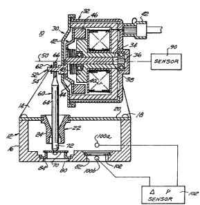
FIGURE 1 i8 a cross~sectional view of an EGR valve con~tructed in
accordance with the teachings of the present invention.
:FIGURE 2 iB a ~ont-sectional ~iew of the valve ~hown in ~IGUR;13
10 1.
Det~iled De~iption of the Drawing~:
An electrically actuated EGR valve 10 i8 shown in ~IGU~E~ 1 and
2. The EGR valve 10 comprises a housing 12 having upper 14 and lower
16 members. The housing members 14 and 16 may be joined together by
fastener~ 18. The housing member 14 includes a cros~ member 20
20 positioned between hou8ing members 14 and 16. A guide member 22 is
supported by the cross member 20.
The guide 22 include~ an inwardly directed lobe 24 which provide~
for a line contact about a valve stem 64 and permit~ the valve 3tem 64 to
25 8wivel relat*e to the lobe 24.
Attached to and supported by the upper housing member 14 is a
torque motor 30. The torque motor 30 i8 e~cemplary of one of the rotary
electronically controlled actuators which may be included within the
30 present invention. Other types of rotary controller~ include rotary
solenoids and DC motors. Suf~ice it to say that the construction of a
torque motor i~ well hlown in the art. The torque motor 30 illustrated
in ~IGUREs 1 and 2 iincludes a housing 32 attached to the upper
hou~ing member 14. Rotatably ~upported relative to a bearing 34 or
07MS1487/1330r l 3 0 8 O q 0 785-87-0020
--4-
bushing (not ~hown) i8 a shaPc 36. Po~itioned about the bearing 34 and
~haflc 36 is a ~tator assembly 38 which includes a coil 40. An electrical
connector 42 ie communicated in a known manner to the ends of the coil
40.
The ~haft 36 comprises a portion of an armature a~embly 42. The
armature as~embly 42 filrther includes a member 44 radially extending
from the shaft 36 and a ferromagnetic element 46, supported by member
44, which reacts wi~h ~ magnetic field generated by the coil 40 to rotate
lo the shaft 36. Positioned about the ~haft 36 and connected to both the
~tator assembly 38 and the member 44 is a bias spring 48. Radially
offset from the agiB 50 of the shaft 36 is another shaft or eccentric 52.
The ~haft 62 includes a narrowed portion 54. A valve ~tem a~sembly 60
is loo~ely secured to the shaft 52 by a retainer 62. The valve ~tem
5 assembly 60 include~ a valve stem 64 having an opening 66 in one end
thereof. The valve stem 64 extends from and is moved by the ~haft 52
and also extends through the guide 22. A free floating poppet valve 70 is
attached to an end 72 of the valve stem 64. As illustrated in the
~IGUREs, the poppet valve 70 i~ rece*ed about a necked-down portion
20 74 of the valve stem 64. The poppet valve 70 i8 loosely secured to the
valve stem 64 to permit it to move relat*ely independently of the valsre
stem.
Reference i~ again made to the lower housing member 16 which
25 additionally include~ an inlet passage 80 and an outlet pas~age 82.
Iypically the inlet passage 80 i8 adapted to rece*ed exhaust gas while
the outlet passage 8~ i~ adapted to communicate the e~haust gas to the
intake manifold of the engine. Positioned about the intake pa~age 80 i~
a valve seat 84 which iB adapted to receive the poppet valve 70 3uch that
30 when the poppet valve is seated upon the valve seat 84 the flow of
exhauet ga~ from the inlet 80 to the outlet 82 i3 prohibited. Further it
can also be seen from ~IGURE 1 that the center of the guide 22 i8
aligned with the center of the valve ~eat 84.
07MS1487/1330r 1 3 0 8 O q 0 785-87-0020
-5-
During periods when the coil 40 is not activated the ~pring 48 will
bias the eccentrically positioned shaft 62 in a clockwise man~er, a~
viewed iD FI~URE 2, such that the poppet Yalve 70 is seated upon the
valve ~eat 84. Further from ~IGU~E 2, it can be ~een that in thi~ closed
5 positioned the axi8 of the eccentrically positioned ~aft 62 is
substantially perpendicular to the axis of the guide 22 and valve ~eat 84
while the a~is 60 of the shaP~ 36 i3 off~et therefrom. In the preferred
embodiment of the invention the ehaf~ 36 of the torque motor 30 is
rotatable through an angle of appro2~imately 70 degrees as measured
o from the closed position. The motion of the shafts 36 and 52 are
illu3trated by arrow 76. Con~equently, because of the above geometry,
the opening of the poppet valve 70 relat*e to the valve seat 40;
e~pecially at small openings, can be precisely controlled.
It is contemplated that the above described EGR valve 10 can be
utilized in at least two modes of operation. The first mode of operation
requires the addition of the rotary ~haft sensor which is generally ~hown
as 90. In practice the ~ensor 90 can easily be incorporated within the
houaing 32 of the torque motor 30. In this mode of operation the angular
20 rotation of the torque motor sha~ 36 is measured by the sensor 90.
Based upon the knowledge of radial offset, r, and the initial angular
o~fset, a, an electronic control unit re~ponsive to the output of the sensor
90 can calculate the gap between the poppet valve 70 and its valve seat
84. Based upon this calculated gap the ECU, in concert with other
25 engine parameters, can estimate in a known manner, the differential
pressure drop across the valve ~eat and hence the amount of e~haust gas
recirculation flow.
The above described EGR valve 10 may be used in a clo~ed loop
30 pres~ure mode of operation wherein pres~ure measurement ports 100a
and 100b are positioned across the outlet passage 82. A differential
pressure sensor 102 connected acros3 the ports 100a and b can be used
to calculate the EGR flow directly ba~ed upon the pressure drop acros3 a
sharp edge orifice 102.
07MS1487/1330r 1 3 0 3 o q o 785-87-oo2o
--6
In operation, ~he shafl; ~6 of the torque motor 30 is commanded, in
re~ponse to engine parameters, to rotate a predetermined amount. This
cause~ the valve stem 64 and poppet valve 70 to move ~way firom the
valve ~eat 84 thereby e~tablishing a predeterimiIIed EGR flow. The
5 eccentrically po~itioned ~haft 52 convert~ the rotational motion OI the
torque motor 30 into ~ubstantially a2cial motion lifting the poppet valve
70 off from its seat 84. A~ can be seen from the above, the motion of the
valve ~tem is not a pure a2cial motion but r~ther a combination of
rotational and a~ial motion. When it i8 des~red to terminate EGR flow
lo the torque motor ia reverEed causing the poppet valve to again ~eat upon
the valve seat 84. Since the poppet valve i8 not rigidly attached to the
valve stem the poppet valve can pivot relative to the valve stem to
permit proper engagernent with the valve seat.
Many change~ and modifications in the above described
embodiment of the invention can, of cour~e, be carried out without
departing firom the ~cope thereof. Accordingly, that ~cope i~ intended to
be limited only by the scope of the appended claims.