Note: Descriptions are shown in the official language in which they were submitted.
- 1 308 1 84
The invention refers to a switch for a floor transportation
system with an automotive electric transportation vehicle having
a guide pin extending into a guide rail below the floor level and
being connected with a steering mechanism of the vehicle. Such a
floor transportation system is known from published German patent
application 34 04 805, which was filed on February 10, 1989.
The known floor transportation system is faced with the
problem of controlling the course in the area of a branching of the
guide rail. Here, the electric transportation vehicle is to be
moved ~electively and by remote control into one or the other
branch guide rail. The present invention ~olves this problem by
mean~ of an electromagnetic ~witch.
The electromagnetic switch according to the present invention
compri~es electromagnets in the ~ide walls facing the branching
points of the guide rails below the floor level. These
electromagnet~ are selectively and alternatively excitable. In
front o~ the guide pin, a guide ~hoe i~ attached pivotably, which
consi~t~ at lea~t partly of a ferromagnetic material.
The invention will now be di~cus~ed with reference to the
drawing~.
Fig. 1 shows a ~ide view of a conventional electric
tran~portation vehicle for a floor tran~portation system;
Fig. 2 ~hows a portion of the electric tran~portation vehicle
of Fig. 1 with modification~ in accordance with the present
invention;
a~
1 30~ 1 84
Fig. 3 shows a top view of a switch area of the guide rails
of the floor transportation system; and
Fig. 4 shows a cross-section along line IV-IV of Fig. 3.
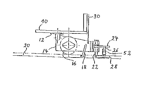
The conventional electric transportation vehicle shown in Fig.
1 has already been described in detail in the above-described
published German patent application 34 04 805. It comprises a
platform for carrying the good~ to be tran~ported. Thi~ platform
10 carries in its front area a turntable 12 which i~ rotatable
about a verticle axis. A steering arm 14 extends forward from thi~
turntable. It carries a front wheel 16. The axis of the front
wheel 16 is directly connected with an electric motor ~not shown).
Further, a current collector 18 is attached to this steering arm
14. The current collector 18 engages a contact rail within a guide
rail 20 below the floor level. The front end of the steering arm
14 carries a guide pin 22 which also extend~ into the guide rail
20. Further, a cantilever arm 24 is pivotably connected to the
front end of the steering arm 14. It has a shaft 26 which extends
~rom the ~teering arm 14. It has a ~haft 26 which extend~ from
its front end downward. A guide shoe 28 is pivotably connected to
the lower end of this shaft 26. This guide shoe 28 ha~ an extended
shape like a boat, a~ shown in Fig. 3. The guide ~hoe 28
consi~ts either co~pletely or at least partly of
iron or another ferromagnetic material 80 that it can
be attracted by an electromagnet. At its front end, the
1 3n81 84
-- 3
guide shoe 28 has a tip. The shaft 26 is connected with the
center of the guide shoe 28 and the guide shoe extends back-
ward approximately to the guide pin 22. The steering arm 14
can be lifted by means of a lifting device 30 so that the
current collector 18, the guide pin 22 and the guide shoe 28
can be pulled out of the guide rail below the floor level.
Fig. 3 shows the switch area of the guide rail 20 below the
floor level. The switch is provided in the area of a
branching point or fork, whereby a branch rail 32 branches
from the guide rail 20 toward the right side. The direction
of movement is assumed to run from the right to the left.
The left side wall of the guide rail (seen in the direction
of movement) is a continuous straight side wall. The right
side wall of the guide rail 20 has a curvature in the area
of the switch. The curved area continues at both ends into a
straight wall area. A wedge-shaped element 34 is provided
behind the switch. It defines the two additional side walls
behind the fork. Several electromagnets 42 are provided one
behind the other at both side walls of the switch area 36,
i. e. at the straight side wall 38 and at the curved side
wall 40. The electromagnets 42 are connected with a power
supply and control device. Each electromagnet consists of a
magnetic core 44 and a coil 46. The magnetic core extends to
the side wall so that the magnetic pole is in the side wall.
An insulating layer 48 is provided above the coil and a
cover plate 50 is provided above the ;nsulating layer. Fig.
4 shows that a further joint 52 is provided within the vertical
shaft 26 of the guide shoe 28, which has a horizontal joint
axis so that the guide shoe ;s p;votable in all directions.
The operation of the switch shall now be described. If an
electric transportation vehicle approaches the switch area,
the electromagnets of the one side or the electromagnets of
1 30~ 1 84
-- 4
the other side are selectively excited. It is now assumed
that the upper electromagnets in Fig. 3, i. e. those at the
curved side wall of the switch, are excited. As soon as the
guide shoe 28 of magnetic material comes into the range of
attraction of the electromagnets, it engages the side wall.
In the area of the side wall, the electromagnets can be
exposed. It is, however, preferred that a cover plate 56 of
non-magnetic material is provided. In the latter case, the
guide shoe 28 engages and slides along this plate 56. This
subjects the steerinsl arm 14 to a torque so that it is
pivoted together with the guide pin 22. This pivotal motion
occurs in the course of the forward movement of the electric
transportation vehicle. Finally, the guide shoe reaches the
end of the switch and enters with its tip into the fork rail
32. This causes also the guide pin 22 to move into the fork
guide rail. In the further course of the movement, this fork
guide rail 32 takes over the guiding function so that the
steering arm 14 is pivoted furSher. After the guide shoe 28
has left the switch area, the electromagnets are turned off.
The sequentially arranged electromagnets 42 can all be
excited simultaneously. They also can be excited one after
the other. If the electric transportation vehicle is
supposed to move in the straight direction, the electro-
magnets 42 shown in Fig. 3 are excited. The guide shoe 28
now engages the stra;ght inner wall of the switch area and
the electric transportation vehicle maintains its straight
travelling direction.