Sélection de la langue

Search

Sommaire du brevet 1308184 

Énoncé de désistement de responsabilité concernant l'information provenant de tiers

Une partie des informations de ce site Web a été fournie par des sources externes. Le gouvernement du Canada n'assume aucune responsabilité concernant la précision, l'actualité ou la fiabilité des informations fournies par les sources externes. Les utilisateurs qui désirent employer cette information devraient consulter directement la source des informations. Le contenu fourni par les sources externes n'est pas assujetti aux exigences sur les langues officielles, la protection des renseignements personnels et l'accessibilité.

Disponibilité de l'Abrégé et des Revendications

L'apparition de différences dans le texte et l'image des Revendications et de l'Abrégé dépend du moment auquel le document est publié. Les textes des Revendications et de l'Abrégé sont affichés :

  • lorsque la demande peut être examinée par le public;
  • lorsque le brevet est émis (délivrance).
(12) Brevet: (11) CA 1308184
(21) Numéro de la demande: 1308184
(54) Titre français: COMMUTATEUR POUR SYSTEME DE TRANSPORT AU PLANCHER
(54) Titre anglais: SWITCH FOR A FLOOR TRANSPORTATION SYSTEM
Statut: Périmé et au-delà du délai pour l’annulation
Données bibliographiques
(51) Classification internationale des brevets (CIB):
  • E01B 07/04 (2006.01)
  • E01B 25/28 (2006.01)
(72) Inventeurs :
  • UTTSCHEID, GEORG (Allemagne)
(73) Titulaires :
  • GEORG UTTSCHEID
(71) Demandeurs :
(74) Agent: OSLER, HOSKIN & HARCOURT LLP
(74) Co-agent:
(45) Délivré: 1992-09-29
(22) Date de dépôt: 1988-10-31
Licence disponible: S.O.
Cédé au domaine public: S.O.
(25) Langue des documents déposés: Anglais

Traité de coopération en matière de brevets (PCT): Non

(30) Données de priorité de la demande:
Numéro de la demande Pays / territoire Date
P 37 36 886.9 (Allemagne) 1987-10-30

Abrégés

Abrégé anglais


ABSTRACT OF THE DISCLOSURE
A switch for a floor transportation system is described,
whereby a guide rail is provided below the floor level. A
guide pin extends into this guide rail. In front of this
guide pin, a guide shoe of ferromagnetic material is
pivotably provided. In the area of the switch, the side
walls of the guide rail are provided with electromagnets
which pull the guide shoe toward the one or the other wall
area so that the guide shoe and the guide pin can be
directed into one or the other branch rail of a guide rail
fork.

Revendications

Note : Les revendications sont présentées dans la langue officielle dans laquelle elles ont été soumises.


THE EMBODIMENTS OF THE INVENTION IN WHICH AN EXCLUSIVE
PROPERTY OR PRIVILEGE IS CLAIMED ARE DEFINED AS FOLLOWS:
1. Switch for a floor transportation system with an
automotive electric transportation vehicle having a guide pin
that extends into a guide rail below the floor level and that is
connected with a steering mechanism of the vehicle, characterized
in that electromagnets are provided in the side wall areas facing
the switch area of the guide rail below the floor level, whereby
these electromagnets are selectively and alternatively excitable
and whereby a guide shoe which consists at least partly of a
ferromagnetic material is pivotably attached in front of the
guide pin.
2. Switch according to claim 1, characterized in that
several electromagnets are provided one behind the other in the
side wall area.
3. Switch according to claim 1, characterized in that the
guide shoe is pivotable about a central vertical shaft in front
of the guide pin.
4. Switch according to claim 3, characterized in that the
guide shoe is additionally pivotable about at least one
horizontal axis and preferably about two orthogonal horizontal
axes.
5. Switch according to claim 4, characterized in that a
joint is provided within the vertical shaft for pivotal motions
about the horizontal axes.
6. Switch according to one of claims 1 to 3, characterized
in that the guide shoe can be pulled out of the guide rail below
the floor level together with the guide pin.
-5-

7. Switch according to one of claims 1 to 3, characterized
in that the electric transportation vehicle has a front turntable
which carries a wheel with an electric drive and the guide pin
and the guide shoe.
-6-

Description

Note : Les descriptions sont présentées dans la langue officielle dans laquelle elles ont été soumises.

- 1 308 1 84
The invention refers to a switch for a floor transportation
system with an automotive electric transportation vehicle having
a guide pin extending into a guide rail below the floor level and
being connected with a steering mechanism of the vehicle. Such a
floor transportation system is known from published German patent
application 34 04 805, which was filed on February 10, 1989.
The known floor transportation system is faced with the
problem of controlling the course in the area of a branching of the
guide rail. Here, the electric transportation vehicle is to be
moved ~electively and by remote control into one or the other
branch guide rail. The present invention ~olves this problem by
mean~ of an electromagnetic ~witch.
The electromagnetic switch according to the present invention
compri~es electromagnets in the ~ide walls facing the branching
points of the guide rails below the floor level. These
electromagnet~ are selectively and alternatively excitable. In
front o~ the guide pin, a guide ~hoe i~ attached pivotably, which
consi~t~ at lea~t partly of a ferromagnetic material.
The invention will now be di~cus~ed with reference to the
drawing~.
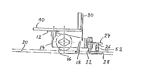
Fig. 1 shows a ~ide view of a conventional electric
tran~portation vehicle for a floor tran~portation system;
Fig. 2 ~hows a portion of the electric tran~portation vehicle
of Fig. 1 with modification~ in accordance with the present
invention;
a~

1 30~ 1 84
Fig. 3 shows a top view of a switch area of the guide rails
of the floor transportation system; and
Fig. 4 shows a cross-section along line IV-IV of Fig. 3.
The conventional electric transportation vehicle shown in Fig.
1 has already been described in detail in the above-described
published German patent application 34 04 805. It comprises a
platform for carrying the good~ to be tran~ported. Thi~ platform
10 carries in its front area a turntable 12 which i~ rotatable
about a verticle axis. A steering arm 14 extends forward from thi~
turntable. It carries a front wheel 16. The axis of the front
wheel 16 is directly connected with an electric motor ~not shown).
Further, a current collector 18 is attached to this steering arm
14. The current collector 18 engages a contact rail within a guide
rail 20 below the floor level. The front end of the steering arm
14 carries a guide pin 22 which also extend~ into the guide rail
20. Further, a cantilever arm 24 is pivotably connected to the
front end of the steering arm 14. It has a shaft 26 which extends
~rom the ~teering arm 14. It has a ~haft 26 which extend~ from
its front end downward. A guide shoe 28 is pivotably connected to
the lower end of this shaft 26. This guide shoe 28 ha~ an extended
shape like a boat, a~ shown in Fig. 3. The guide ~hoe 28
consi~ts either co~pletely or at least partly of
iron or another ferromagnetic material 80 that it can
be attracted by an electromagnet. At its front end, the

1 3n81 84
-- 3
guide shoe 28 has a tip. The shaft 26 is connected with the
center of the guide shoe 28 and the guide shoe extends back-
ward approximately to the guide pin 22. The steering arm 14
can be lifted by means of a lifting device 30 so that the
current collector 18, the guide pin 22 and the guide shoe 28
can be pulled out of the guide rail below the floor level.
Fig. 3 shows the switch area of the guide rail 20 below the
floor level. The switch is provided in the area of a
branching point or fork, whereby a branch rail 32 branches
from the guide rail 20 toward the right side. The direction
of movement is assumed to run from the right to the left.
The left side wall of the guide rail (seen in the direction
of movement) is a continuous straight side wall. The right
side wall of the guide rail 20 has a curvature in the area
of the switch. The curved area continues at both ends into a
straight wall area. A wedge-shaped element 34 is provided
behind the switch. It defines the two additional side walls
behind the fork. Several electromagnets 42 are provided one
behind the other at both side walls of the switch area 36,
i. e. at the straight side wall 38 and at the curved side
wall 40. The electromagnets 42 are connected with a power
supply and control device. Each electromagnet consists of a
magnetic core 44 and a coil 46. The magnetic core extends to
the side wall so that the magnetic pole is in the side wall.
An insulating layer 48 is provided above the coil and a
cover plate 50 is provided above the ;nsulating layer. Fig.
4 shows that a further joint 52 is provided within the vertical
shaft 26 of the guide shoe 28, which has a horizontal joint
axis so that the guide shoe ;s p;votable in all directions.
The operation of the switch shall now be described. If an
electric transportation vehicle approaches the switch area,
the electromagnets of the one side or the electromagnets of

1 30~ 1 84
-- 4
the other side are selectively excited. It is now assumed
that the upper electromagnets in Fig. 3, i. e. those at the
curved side wall of the switch, are excited. As soon as the
guide shoe 28 of magnetic material comes into the range of
attraction of the electromagnets, it engages the side wall.
In the area of the side wall, the electromagnets can be
exposed. It is, however, preferred that a cover plate 56 of
non-magnetic material is provided. In the latter case, the
guide shoe 28 engages and slides along this plate 56. This
subjects the steerinsl arm 14 to a torque so that it is
pivoted together with the guide pin 22. This pivotal motion
occurs in the course of the forward movement of the electric
transportation vehicle. Finally, the guide shoe reaches the
end of the switch and enters with its tip into the fork rail
32. This causes also the guide pin 22 to move into the fork
guide rail. In the further course of the movement, this fork
guide rail 32 takes over the guiding function so that the
steering arm 14 is pivoted furSher. After the guide shoe 28
has left the switch area, the electromagnets are turned off.
The sequentially arranged electromagnets 42 can all be
excited simultaneously. They also can be excited one after
the other. If the electric transportation vehicle is
supposed to move in the straight direction, the electro-
magnets 42 shown in Fig. 3 are excited. The guide shoe 28
now engages the stra;ght inner wall of the switch area and
the electric transportation vehicle maintains its straight
travelling direction.

Dessin représentatif
Une figure unique qui représente un dessin illustrant l'invention.
États administratifs

2024-08-01 : Dans le cadre de la transition vers les Brevets de nouvelle génération (BNG), la base de données sur les brevets canadiens (BDBC) contient désormais un Historique d'événement plus détaillé, qui reproduit le Journal des événements de notre nouvelle solution interne.

Veuillez noter que les événements débutant par « Inactive : » se réfèrent à des événements qui ne sont plus utilisés dans notre nouvelle solution interne.

Pour une meilleure compréhension de l'état de la demande ou brevet qui figure sur cette page, la rubrique Mise en garde , et les descriptions de Brevet , Historique d'événement , Taxes périodiques et Historique des paiements devraient être consultées.

Historique d'événement

Description Date
Inactive : Regroupement d'agents 2013-10-22
Inactive : CIB de MCD 2006-03-11
Inactive : Demande ad hoc documentée 1995-09-29
Le délai pour l'annulation est expiré 1995-03-29
Lettre envoyée 1994-09-29
Accordé par délivrance 1992-09-29

Historique d'abandonnement

Il n'y a pas d'historique d'abandonnement

Titulaires au dossier

Les titulaires actuels et antérieures au dossier sont affichés en ordre alphabétique.

Titulaires actuels au dossier
GEORG UTTSCHEID
Titulaires antérieures au dossier
S.O.
Les propriétaires antérieurs qui ne figurent pas dans la liste des « Propriétaires au dossier » apparaîtront dans d'autres documents au dossier.
Documents

Pour visionner les fichiers sélectionnés, entrer le code reCAPTCHA :


Pour visualiser une image, cliquer sur un lien dans la colonne description du document. Pour télécharger l'image (les images), cliquer l'une ou plusieurs cases à cocher dans la première colonne et ensuite cliquer sur le bouton "Télécharger sélection en format PDF (archive Zip)" ou le bouton "Télécharger sélection (en un fichier PDF fusionné)".

Liste des documents de brevet publiés et non publiés sur la BDBC .

Si vous avez des difficultés à accéder au contenu, veuillez communiquer avec le Centre de services à la clientèle au 1-866-997-1936, ou envoyer un courriel au Centre de service à la clientèle de l'OPIC.


Description du
Document 
Date
(aaaa-mm-jj) 
Nombre de pages   Taille de l'image (Ko) 
Abrégé 1993-11-03 1 11
Revendications 1993-11-03 2 33
Dessins 1993-11-03 2 28
Description 1993-11-03 4 125
Dessin représentatif 2002-02-10 1 7