Note: Descriptions are shown in the official language in which they were submitted.
B7453~30
2~
,
NONWOVEN ~ATERIAL SU~JECTED TO HYDRAULIC JET
TREATMENT IN SPOTS, AND METHOD AND APPARATUS
FOR PRODUCING THE SAME
BACK~ROUND OF THE INVENTION
The present invention relates to a bonded nonwoven
mat~rial, and method and apparatuæ for for~ing the same. In
particulax, the pr~sent invention relats~ to a ncnwov~n web
(either elastic or nonelastic), and a nonwoven laminate
(e.g., a nonwoven fibrous elastic laminat~ comprising at
least one nonwoven elastic web together wikh at least one
~urther nonwovPn web), with the material (either a single
web or laminate) being bonded to form the bonded nonwoven
m&terial.
It has been desired to provide bonded nonwoven materials
(e.g., nonwoven webs, either elastic or nonelastic, of a
single web or of a laminate) having high overall bulk, hand
and drape. It has baen particularly desired to provide such
nonwoven material having high overall bulk, fro~ an initial
material with high bulk but not sufficiently
self-supporting, wherein the final product (which is
sufficiently self-supporting) has been bonded while avoiding
any substantial decrease in overall bulk, the final product
retaining good hand and draping properties after bonding.
It has also been desired to provide nonwoven elastic
laminates that are both stretchable and resilient, and which
retain good hand and draping properties after bonding.
U.S. Patent No. 4,016,317 to Kalwaites discloses
nonwoven fabrics having patterns of areas of low fiber
density or holes and patterns of fiber bundles of paral-
lelized consolidated fiber s g~ents, the predetermined
pattern o~ areas being partially or entirely de~ined by
yarn-like fiber bundles, the ~unctures in the fabric (that
is, the areas where the fiber bundle~ intersect one another)
possibly comprising areas of highly entangled fiber
segments. The described fabric has one surface which is
smooth and substantially free of fiber ends, while the
2 ~3~8~
opposite surface contain~ a plurality o~ fiber ends held
together by a binder to form tufts of bonded ~iber ends on
tha ~ux~ace. This pat~nt discloses that the fabrlc is
~ormed by placing a ~ibrous web comprising 5taple length
fibers on a foraminous support wire, the foraminou~ support
havlng from about 209 to about 8100 openings per square inch
to provida ~rom about 20 to 70% open area in ths support so
that the staple length fibers will span at least two of the
openings, with fiber rearranging ~orces being directed
against the fibrous web to move ~iber seg~ent~ into closer
proximity to one another and increased parall~lism to
form ~iber bundles defining areas of low ~iber density
therebetween, individual fiber end~ b~ing forced down
through tha openings in the foraminous support member. This
patent discloses specific apparatus including a rotatable
apertured drum. Insid~ th~ drum is a stationary manifold to
which a fluid is applied: on one side of the mani~old is a
series of nozzles for directing the fluid toward the drum
periphery. A backing belt extends about a large portion of
the periphery o~ the drum, and, together with the apertured
drum, provides a rearranging zone between them through which
a fibrous material moves to be rearranged, under the
influence of applied fluid forces, into a nonwoven fabric
having the previously discussed pa~tern.
XalwaitQs describes use of staple length fibers which
span at least two of the openings in the support wire; the
present invention is not so limited, and, as discussed
further herein, is applicable to fibers having lengths less
than staple fibers (that is, is applicable to pulp fibers,
even those having lengths less than 0.25 inch). In
Kalwaites, fiber rearrangement occurs so as to provide areas
of low fiber density: such areas of low fiber density are
weak points in the final structure. In the present
invention, on the other hand, the holes and low density
areas are limited; and when meltblown fibers ara used in the
present invention, areas o~ low fiber density are avoided.
3 ~3~8~
U.S. Patent No. 3,485,706 to Evans discloses a
textile-likc nonwoven fabric and a process and apparatlls
for its production, wherein th~ fabric has fibers randomly
entangled with each othar in a repeating pattern of local-
ized entangled region~ intarconnected by fibars extending
between ad;acent entangled regions. The proces~ disclosed
in thi~ patent involv~ supporting a layer of ~ibrous
material on an apertured patterning member for treatment,
jetting liquld supplied at pressures of at least 200 pounds
per squaxe inch (psi) gauge to form 6treams having over
23,000 energy flux in foot pounds/inch2.second at the
treatment distance, and traversing the supporting layer of
fibrous material with the streams to entangle ~ibers in a
pattern determined by the supporting member, using a
suffic:ient amount o~ treatment to prsduce uniformly
patt~rned fabric. Ths initial material is disclosed to
consist of any web, mat, batt or the like of loose fibers
disposed in random relationship with one another or in any
degre~ of alignment.
U.S. Patent No. 4,209,563 to Sisson discloRes a method
of forming an elastic cloth skructure, and the cloth
structure formed, including simultaneously melt spinning a
stream of filaments of fiber-forming synthetic organic
polymer from an extruder through a die or a spinnerette, the
filaments then being mechanically reduced to textile denier
by being drawn, e.g., by a draw roll, the drawn filaments
then being forwarded by forwarding means to random or
directed formation onto a moving porous forming surface,
with the filaments being bonded following laydown or
collection. In accordance with one aspect disclosed in this
patent, a cloth structure is formed comprised of at least
two types of preferably continuous filaments, at least one
of which is relatively elastomeric and at least one of which
is elongatable but relatively nonelastic: ~t least one of
these ~ypes of filaments is dispersed to provide ~requent
random fiber crossings at least some of which ara bonded,
either directly or indir~ctly and preferably autogenously,
4 ~Q~
to form a coherent cloth. Subsequent to forming the
coherant (bondPd) cloth, th~ bonded cloth, e.g., is
strstched, praferably substantially and uniformly in at
least one direction, followed hy ubstantially complete
cloth relaxation to develop a low modulus o~ elasticity
therein in at least such one direction. Thi patent goes on
to describe that the relatively elastomeric ~ilament3 and
elongatable but relatively nonelastic ~ilaments can be laid
as superposed layer3 or as a mixed layer to provid~ numerous
well di~persed ~iber crossing~ w~ld bonded ~y thQ appli-
cation of heat and pressure to at least som~ of the ~iber
crossings to provide a coherent bonded nonwoven cloth.
U.S. Patent No. 4,296,163 to Emi et al di~closes a
fibrous composite having elasticity, comprised of a
coalesced assembly of (A) a sheet-like mesh structure
composed of fibers of a synthetic elastomeric polymer, the
individual fibers of which are interconnected at random in
irregular relationship to ~orm a number o~ meshes of
different sizes and shapes, with the mesh structur~ havin~ a
recovery ratio after 10~ stretch cf at least 70~ in two
arbitrarily selected, mutually perpendicular directions on
the plane of the mesh structur2, and (8) a mat-, web- or
sheet-like fiber structure compo~ed of short or long fibers,
with the fiber structure having a recovery ratio after 10%
stretch of less than 50~ in at least one arbitrarily
selected direction. It is stated that the formed elastic
composite is suitable for various apparel~based materials
and industrial materials such as filter cloths, absorbents,
and heat insulating ma~erials.
U.S0 Patent No. 4,514,455 to Hwang disclo~es a composite
nonwoven fabric which comprises a batt of crimped polyester
staple fibers and a bonded sheet o~ ubstantially continuous
polyester filaments. The batk and sheet are in surface
contact with each other and are attached to each other by a
series of parallel seams having a spacing of at least 1~7 cm
between su~cessive seams. In one embodiment, the seams are
jet track which are a result of hydraulic stitching. In
5 ~3~8~
the fabric produced in Hwang, the bondc are interconnected
in the continuou~ ~et tracks, whil2 in tha pres2nt invention
the s~ot~ of bonding area are not connected with each other.
U.S. Reissu~ Pakent No. 31,ZOl to Ikeda et al discloses
a fabric, useful as a substratum for arti~icial leather,
which comprlses a woven or knitted fa~ric constitusnt and a
nonwoven fabric constituent. The nonwov~n ~abric
constituent consists sf numerous extremely fine individual
~ibers which have an averags diameter of 0.1 to 6.0 microns
and whioh are randomly distribut~d and entangled with each
other to form a body Or nonwoven rabric. The nonwoven
fabric constituent and the woven or knitted fabric
constituent ar~ superimposed and bonded together, to form a
body of composite fabric, in such a manner that a portion of
the extremely fine individual fibers and the nonwoven
fabric constituent penetrate into th2 in~ide o~ the woven or
knitted ~abric constituent and are entangled with a poxtion
of the fibers therein. The composite fabric is disclosed as
being produced by superimposing the two fabric const$tuents
on each other and jetting numerous fluid streams ejected
under a pressure of from 15 to 100 kg/cm2 toward the surface
of the fibrous web constituent. This patent discloses that
the extremely fine fibers can be produced by using any of
the conventional fiber-producing methods, pre~erably a
meltblowing m~thod.
U.S. Patent No. 4,446,1~9 to Romanek discloses a
nonwoven textile fabric laminate which includes at least
one layer of nonwoven textile fabric which is elongatable,
and which is secured by needle punching to an elastic layer
so that the nonwoven layer o~ textile fabric will be
permanently stretched when the elastic layer is dra~ted
within its elastic limits. After such drafting, when the
elastic layer is allowed to relax and return to substan-
tially its condition prior to being drafted, the nonwove~
fabric layer ~s stated to exhibit increased bulk as a result
of its concurrent relaxation. It is also stated~that the
6 ~3~32~
nonwoven textile ~abric laminate may be utilized to form
wearing apparel which ha~ enhanced freedom of movement.
U.S. Paten~ No. 4,657,802 to Morman disclose~ a process
for producing a composite nonwoven elastic web which is
composed of ~ nonwoven elastic web that i5 joined to a
fibrous nonwoven gathered web, and the composite web
formed. The composite elastic web, according to U.S. Patent
No. 4,657,802, is formed by joining the fibrous nonwov~n
gatherable web to the nonwoven elastic web (e.g., forming
the gatherable web on the elastic web) while the nonwoven
elastic web is maintained at an elonga~ed (stretched),
biased length; because the ~ibrou~ nonwoven gatherable web
is formed onto the sur~ace o~ the nonwoven elastic web while
the elastic web is being maintained at lt~ stretched, biased
length, the ~ibrous nonwoven gatherable web i8 in an
ungathered but gatherable condition. In one embodiment
descrihed in this pat~nt, joining of the gatherable and
slastic webs i5 achieved by heat-bonding to fuse the two
webs to each other; in another embodiment, joining of the
fibrouc nonwoven gatherablQ web to the stretched nonwoven
elastic web is achieved solely by the entanglement of the
fibers of the fibrous nonwoven gatherable web with the
nonwoven elastic web during formation of the fibrous
gatherable web on the surfacs of the elastic web. In
connection with this latter embodiment, the patent discloses
that if the nonwoven elastic web is a fibrous nonwoven
elastic web formed by, e.g., meltblowing, entanglement of
the fibers of the fibrous nonwoven ~atherable web wi~h the
fibrous nonwoven elastic web is achieved by entanglement of
the fiber~ of the fibrous gatherable web with the fibers of
the fibrous elastic web. In a still further embodiment
describ~d in this patent, the nonwoven elastic web is made
out of a tacky elastic material, whereby the fibrous
nonwoven gatherable material is adhesively joined to the
surface o~ the tacky elastlc web. ~his patent goes on to
di~close that, in any of these embodiments, after joining of
the two webs to each other to for~ a composite elastic web,
7 ~.~Q8~
the biasing force i8 removed frsm the composite nonwoven
elastic web and the composite elastic web is allowed to
ralax to its normal relaxed, unbia~ed length, resulting in
the gatherabls web being carried with khe contracting
nonwoven elastic web and thu~ being gathered.
Notwithstanding the teachings of the above-discussed
references, it is desired to provlde bonded nonwoven
material having high overall bulk, and, ln particular,
wherein the overall bulk o~ the material subjected to
bonding (to form the bonded nonwovQn materlal) i8 not
substantially decreased by the bonding, while providing a
bonded nonwoven material having good hand and drape. It is
desired to provide a bonded nonwoven material, of either a
single web or a laminate, of an elastic and/or a nonelastic
lS material, havlng high overall bulk and good hand and drape~
It i5 desired to provide such bonded nonwoven material
without use of conventional bonding technigues such a
fusion or chemical bonding, mechanical needling, etc.
Moreover, notwithstanding the teachings of the
above-discussed references, there is still a des$re to
provide bonded ~lastic nonwoven materials that retain high
overall bulk after bonding and have good stretch and
recovery properties, without decreased hand and draping due
to the bonding. Moreover, it is itill desired ~o provide a
nonwoven elastic laminate material (e.g., a nonwoven elastic
laminate web) that is cloth-like, stretchable and resilient,
yet which retains good hand and drape properties after
bonding. More particularly, it is desired to provide a
stretchable cloth-like nonwoven laminate without the use of
conventional laminate bonding mèthods, e.g., without
mechanical needling, fusion, chemical bonding, etc.
It is furthar desired to provide a nonwoven ~aterial,
either a single web or laminate, of elastic and/or non-
~lastic material, haviny the properties discussed abo~e,
by a simple ~ethod, using simple apparatus.
While the above-discussed documents may disclose
products, processes and app ratus which exhibit some of the
~3~382~
characteristics of the present invention, none of them
discloses or suggests the present invention, including the
advantages thereof, which achieve the objectives as discussed
below.
Generally speaking, the present invention relates to a
spot-entangled material which includes at least one nonwoven
web having two surfaces, and spot-entangle-bonds in which the
material of the nonwoven web is entangled and intertwined in
the thickness direction between the two surfaces.
According to one embodiment of the present invention,
the spot-entangle-bonded nonwoven material has a high overall
bulk and increased texture, and good hand and drape.
In one embodiment of the present invention, the spot-
entangle-bonded nonwoven material is either a single web or a
laminate. ~he bonded nonwoven material may be either elastic
or nonelastic, have a high overall bulk, and good hand and
drape, and is provided without using conventional bonding
means such as fusion or chemical bonding, or mechanical
needling so that good hand and drape properties can be
retained after bonding.
According to one aspect of the present invention,
hydraulic entanglement is used to spot-entangle-bond (jet
treat) unbonded nonwoven material (either a single web or a
laminate). The material (e.g., fibers of the web or laminate)
being entangled and intertwined only in spots (that is, not
over the entire surface of the material). By utilizing
hydraulic entanglement of the web (or laminate) in spots, the
overall bulk of the web (or laminate) is substantially
retained, as compared, e.g., to bonding by hydraulic
entanglement of the web over the entire surface thereof. In
one embodiment of the present invention a bonded product is
provided with a limited number of pin holes, or no pin holes
by providing the bonds by spot-entangle-bonding (spot-jet
treated). Since the spot-entangle-bond is substantially
independent of the composition of the nonwoven material (as
long as the material can be spot-entangle-bonded), nonwoven
materials of dissimilar composition can be bonded; moreover
_~ .
-~^
bonding can be provided without producing film-like materials
(in particular, film-like materials are formed at bond points
when thermal spot-bonding is used).
Generally, spot-entangle-bonding (either of a single web
or of a laminate) provides a material having greater overall
bulk as compared to a material fusion-bon~ed or bonded with
adhesives over the entire surface, or subjected generally to
hydraulic entanglement. Such spot-entangle-bonded materials,
including laminates, have a wide range of uses, from
disposables, e.g., absorbents, wipes and outer covers, etc.,
to durable goods.
While a substantial part of the remainder of the present
disclosure is directed to forming nonwoven elastomeric
laminates, embodiments of the present invention are not
limited thereto, and may include spot-entangle-bonded single
nonwoven webs of either elastomeric or nonelastic material
(e.g., single nonwoven fibrous webs, such as single nonwoven
meltblown webs), or a non-elastic laminate. Embodiments of
the present invention includes nonwoven webs, or laminates,
of pulp fibers that have been spot-entangle-bonded. For
example, nonwoven webs of 100% cellulose fibers that have
been spot-jet-treated, including (1) a single layer of 100%
wood pulp fibers, (2) a laminate of wood pulp fiber layers
(including layers of different wood pulp fibers) etc.
Embodiment of the present invention includes nonwoven webs of
staple fibers that have been spot-entangle-bonded. Another
embodiment of the present invention is a spot-entangle-bonded
web of a coform (admixture) of meltblown fibers and further
fibrous material (e.g., pulp fibers and/or staple fibers
and/or meltblown fibers and/or continuous filaments), with or
without particulate material. Where laminates are spot-
entangle-bonded, the nonwoven webs need not even be fibrous;
for example, two layers of foam polymer material can be
spot-entangle-bonded within the scope of the present
invention where at least one of the two layers includes a
..
~B~
fibrous material or at least one fibrous layer is provided
between the two foam layers, the entangling jet streams
having sufficient force to entangle sufficient portions of
the two layers of the foam and the fibrous material. Thus,
the present invention is useful generally for providing a
bonded material having retained overall bulk and retained
hand and feel.
A nonwoven elastomeric laminate embodiment of the
present invention may be produced by providing a composite of
a nonwoven elastomeric web together with at least one ~urther
nonwoven web, and utilizing hydraulic entanglement to spot-
entangle-bond such tow or more webs together to form a
laminate, with the fibers of the webs being entangled only in
spots (that is not over the entire interface between the
webs). Generally speaking, high pressure water jets may be
directed at a surface of one of the webs, while the webs are
positioned adjacent to each other, so as to spot-bond the
webs together by mechanically entangling and intertwining
fibrous material of the webs only at such spots. By such
spot-entangle-bonding of the webs, one embodiment of the
present invention remains stretchable and resilient;
moreover, since conventional bonding methods, such as
mechanical needling, fusion or chemical bonding, are not
used, good hand and drape properties can be readily retained
after the bonding. Furthermore, since thermal bonding is not
used, the elasticity of the nonwoven elastomeric web is not
destroyed, so that the bonding area can be increased (as
compared, e.g., to spot-bonding using thermal bonding)
without a deleterious effect on the elasticity of the
elastomeric web.
In one embodiment of the present invention the nonwoven
elastomeric web of the laminate i5 a meltblown elastomeric
web that has been subjected to a pre-entangling step, prior
to the spot-entangle-bonding. Such pre-entangling (that is,
a pre-entangling of the meltblown elastomeric web over the
entire surface thereof) provides bundles of the meltblown
fibers and aligns the fibers in the web. Such pre-entangling
~3Q~
11
also opens the web to allow better penetration during the
spot-entangle-bonding. The pre-entangling is performed to
improve the spot-entangle-bonding, and to improve the
elasticity of the laminate.
Various laminate embodiments o~ the present invention
have a wide range of uses, from disposables such as wipes,
outer covers (e.g., for diapers), etc., to durable goods.
In one aspect of the present invention, by utilizing
hydraulic entanglement so as to entangle fibers, in spots, of
the at least two webs, the laminate can easily and
efficiently be provided.
With respect to individual webs utilized to provide the
laminate, in one embodiment the two adjacent webs desirably
are to contain a sufficient amount of fibrous material (e.g.,
fibers) that can be readily entangle-bonded with material
(such as fibrous material) of the adjacent web. These fibers
that entangle-bond with fibrous material of the adjacent web
must have sufficient fiber mobility, small enough diameters
and a sufficient number of loose ends in order to wrap around
fiber cross-over points. According to one embodiment of the
invention, webs made from natural or synthetic pulp fibers,
staple fibers, meltblown fibers, or coforms (that is, an
admixture of (1) meltblown fibers and (2) pulp fibers and/or
staple fibers and/or meltblown fibers and/or continuous
filaments, with or without particulate material) have been
shown to be effective for entangling less mobile fibers.
Furthermore, one aspect of the present invention is an
apparatus for spot-entangle-bonding or spot-jet-treating,
whereby the spot-entangle-bonded webs of the present
invention can easily be obtained.
The present invention also resides in an apparatus for
manufacturing a bonded nonwoven material having spot-bonds
provided by hydraulic entanglement. The apparatus has a
support member, adapted to have a nonwoven material to be
subject to the hydraulic entang~ement adjacent thereto with
means for locating the nonwoven material adjacent the support
,..~
~8~
12
member. The apparatus also has means for providing high
pressure liquid jets to be directed against the nonwoven
material while adjacent the support member, the high pressure
liquid jets being adapted to hydraulically entangle the
material of t~e nonwoven material. De~ector means are
adapted to be positioned between the nonwoven material to be
subjected to the hydraulic entanglement and the means for
providing high pressure liquid jets for deflecting the high
pressure li~uid jets such that only separated spots of the
nonwoven material are subjected to hydraulic entanglement so
that spot-entangle-bonds, provided bv hydraulically entangled
material of the nonwoven material, are produced.
An illustrated embodiment of the apparatus of the
invention utilizes a perforated member, with the web (or
composite webs) to be spot-entangle-bonded being positioned
adjacent or at least close to the perforated member, and with
water jets passed throu~h the openings in the perforated
member so as to hydraulically entangle fibers and form the
spot-entangle-bonds. The web (or composite of webs) can be
positioned first with one side and then with the opposed side
adjacent the perforated member, so as to provide spot-bonding
of both sides thereof; such spot-bonding of both sides is
particularly appropriate when a sandwich of webs, having an
intermediate elastomeric web and sandwiching webs of fibrous
material, is used, with the sandwiching webs containing a
suf~icient number of fibers that can readily entangle-bond
with other fibers.
In yet another embodiment of ths apparatus o~ the
present invention, the perforated member is a rotatable
apertured drum, with the water jets positioned inside the
drum and directed through the openings in the drum against
the web (or composite) on the circumference of the drum. The
water jets preferably direct the water perpendicularly to the
web being treated. By this, water jets can be applied on and
3~ off so as to provide the spot bonding. A support is provided
adjacent the outer surface of the drum to support the web (or
~3082~
composite) adjacent or at least close to the drum; such
support is normally apertured. An apertured drum wherein the
circumferential wall (that is, the wall having the apertures)
has a relatively small thickness (e.g., 1/16" rather than
3/8") may be used to provide effective entangle-bonding. By
using the rotatable apertured drum with the drum rotating so
the linear speed of the circumference is substantially the
same as that of the web ~laminate), a continuous web
(laminate) can be spot-entangle-bonded at one side.
The apparatus of the invention, for producing the
hydraulically spot-entangle-honded laminates may include two
perforated drums, with the web (composite) contacting (or
nearly contacting) the circumference of the drums so as -to
direct water jets on the web through the perforated drum and
provide the spot-entangle-bonds. The two perforated drums
may be so situated that initially one side of the web
(composite) is adjacent the first drum, and then the second
side of the web (composite) is adjacent the second drum. By
use of this specific embodiment, including the two drums,
synchronization and control of the bonding pattern, with both
sides of the fabric being bonded, can easily be achieved.
Moreover, noting that the spot-entangle-bonds are dependent
upon the aperture pattern in the drums, the use of drums
allows the bonding patterns to be easily shanged;
furthermore, the use of the drums allows faster line speeds.
It may be saen that the use of the drums readily allows
the elastic webs to be controllably stretched, at the time of
the spot-entangle-bonding, whereby a stretchable nonwoven
elastomeric laminate, having desired stretch and recovery
characteristics, can be easily achieved. In addition, use of
the drums reduces various common production problems faced in
formin~ stretch-bonded laminates, including material
uniformity, drawing of the material, etc. Use of such
controlled stretch, when providing the spot-bonding, and the
product formed thereby, is also part of the present invention.
The apparatus is very versatile, since the bonding and
. ,~ ~. ~ ,
, :,...
2~
14
product characteristics, including any bonding pattern, can
be easily modified by changing drums. Moreover, the
apparatus efficiently uses energy (that is, energ~ to provide
the jets of water for the spot-entangling).
The present invention also resides in a process of
forming a bonded nonwoven material, the process including the
steps of providing at least one nonwoven web and subjecting
the a~ least one nonwoven web to h~draulic entanglement so as
to provide spot entangle-bonds through the at least one
nonwoven web. The hydraulic entanglement is per~ormed so as
to entangle and intertwine material of the at least one
nonwoven web, through the at least one nonwoven we~, in
spots. The hydraulic entanglement being carried out by
jetting a plurality of high-pressure liquid streams toward a
surface of the at least one nonwo~en web and de~lecting the
stream so as to provide the spot-entangle-bonds.
Thus, various embodiments of the present invention
permit formation of bonded nonwoven material, including
r~onwoven elastic laminates of various materials, without
consideration of whether conventional bonding techniques
(e.gO, fusion or chemical adhesives can be utilized with such
materials. Moreover, and as indicated previously, various
embodiments of the present invention provide a laminate
having cloth-like properties, with good hand and drape
properties after bonding.
BRIEF DESCRIPTION OF THE DRAWINGS
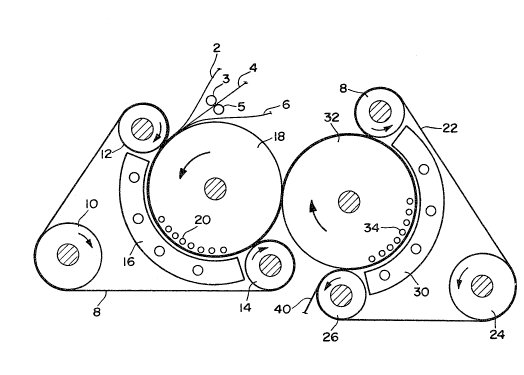
Fig. 1 is a schematic view of an apparatus for forming a
nonwoven hydraulically entangled elastic laminate o~ the
present invention;
Fig. 2 shows a perforated drum used in the apparatus of
the present invention; and
Figs. 3A and 3B are photomicrographs of respective
opposed sides of a spot-bonded laminate of the present
invention.
~Q~2~
14a
DETAILED DESCRIPTION OF TEIE INVENTION
While the invention will be described in connection with
specific and preferred embodiments, it will be understood
that it is not intended to limit the invention to those
embodiments. On the contrary, it is intended to cover all
alterations, modifications and equivalents as may be included
within the spirit and scope of the invention as defined by
the appended claims.
The present invention contemplates a nonwoven material
formed by spot-entangle-bonding at least one nonwoven web
(e.g., a nonwoven fibrous web, including a single web of 100
wood pulp fibers~, the spot-entangle-bonds being formed by
hydraulic entanglement. Laminates of at least one nonwoven
web te.g., a web of foam polymer material, a
,,~
, ,., , ~
15 ~
nonwoven fi~rous web) with other fabric materials, 6uch as
wov~n and knit materlals, with ~he laminatss being bonded
togeth~r ~y spot-en~angle-bonds, are also within the
contemplation o~ ths present in~ention.
S As a specific embodim~nt, the present invention contem-
plates a nonwoven elastic laminate ~ormed by spot-bonding a
nonwoven elastic web to another nonwo~en web, the spot-bonds
being formed by hydraulic entanglement. To make tha bonded
laminates, high pre~ure water jets are used to
entangle~bond spo~s o~ the laminated web together. That
is, specific areas o~ the interface betweeen two web3 o~ a
composite have fibrous material from each o~ the webs
hydraulically entangled together due to the high-pressure
je~ , while other areas do not have fibers ~rom each of the
webs hydraulically entangled due to the jets. By
hydraulically entanglod, we mean that ~ibrous portions
(e.g., fibsrs) of the two webs mechanically çrltangle and
intertwine together due to high pressur~ liquid columnar
streams jetted toward a surface o~ tha composite.
Prior to further description of the present inv~ntion,
various terms utilized herein will be defined. ~hus, the
terms "elastic" and "elastomeric" are used interchangeably
herein to mean any matexial which, upon application of a
force, is stretchable to a stretched length which is at
least about 110% of its relaxed length, and which will
recover at least about 40% of its elongation upon release of
the stretching, elongating force. For many uses (e.g.,
garment purpo~e~, a large amount of elongation (e.g., over
12%) is not necessary, and the important criterion is the
recovery property. Many elastic materials may be stretched
by much more than 25% of their relaxed length and many of
these will recov~r to substantially their original relaxed
length upon r~lease of th~ stretching, elongating force.
As used herein the term "recover" ref~rs to a contrac-
tion of a 6tretched material upon termination o~ a biasing
force following stretching of the ~atarial by appli~ation of
the bia~ing force. For example, if the material having a
16 ~3~
relaxed, unbiased length of one (1) inch was elongated 50~
by strQtching to a length of 1 and 1/2 (1.5 inches the
material would have a ~tretched length that is lS0% of its
relaxed length. If this exemplary stretched material
S contrac~ed, that is recovered, to a length of 1 and 1/10
(1.1) inches, after release of the bia~ing and ~tretchiny
force, tha material would have recovered 80% (0~4 inch) of
its elongation.
As used herein, the term "m21tblown fibers" means fibers
formed by extruding a molten thermoplastic material through
a plurality of fine, usually circular, die caplllar~es as
molten threads or filaments into a high velocity ~as (e.g.,
air) stream which attenuates the filaments of molten
thermoplastic material to reduce thelr diameter. There-
lS a~ter, the meltblown fiber are carried by the hlgh veloc~ty
gas stream and are depositeA on a collecting su~ace to form
a web of randomly dispersed meltblown fibers (~.g., micro-
fibers). Such a process is disclosed, for example, in
U.S. Patent No. 3,849,241 to Buntin et al.
As used herein, I'polymer" includes both homopolymers and
copolymers. ~oreover, "nonwoven webs" include any nonwoven,
including nonwoven web~ formed solely of staple fibers,
solely of pulp fibers, etc.
Generally, materials for adjacent webs to be
spot-entangle-bonded can be materials as described in the
previously discussed U.S. Patent No. 4,657,802 to Morman.
Illustratively, the nonwoven web can be a meltblown web of,
e.g., elastomeric or nonelastomeric materials. Exemplary
of nonelastomeric materials are various polyester or
polyolefin materials, including polyethylene terephthalate
and polypropylene. Such web can be a cs~orm of the
meltblown fibers together with pulp and/or ~taple fibers,
the staple ~ibers being synthetic and/or natural staple
fibers. As for such coform material~, containing an
admixture of (1) meltblown and (2) staple and/or pulp
, : .
~ ~4~ ~2 ~ ~
fiber~, see U.S. Patent No. 4,100,324 to Anderson et al
In ~ddition, such web~ can also have particulate
matQrlal incorporatad therein, including, e.g., ~uper
S absorbent ma~erial~. A preferable technique with respect to
the inclusion o~ super-absorbent material i8 to include a
material in the coform whlch can be chemically modlfled to
absorb wa~er after the hydraulic entanglement treatment,
such as disclosed in U.S. Patent No. 3,563,241 to Evans, et
al. Other techniques for modifying the water solubility
and/or absorbency are described in U.S. Patent
NosO 3,37g,720 and 4,128,6~2 to Reid.
Alternatively, such nonwoven webs can be web~ made from
staple fibers, such as, e.g., carded webs, known in the
art. Other type~ of webs, including, e.g., web~ becoming
fibrous during the hydraulic entangling, can be used for the
nonwoven web, as long as they, together with the nonwoven
elastomeric web, can be hydraulically entangled to form the
spot-bonded laminate.
For example, in providing a laminate with sandwiching
webs ~ and C, and with ~ a3 an intermediate, ~lastic
meltblown web, the meltblown fibers have substantial length
and are less mobile. Accordingly, the webs A and C should
contain a sufficient number of fibers having sufficient
fiber mobility, small enough diameters and loose ends so as
to wrap around fiber cross-over points.
As for the nonwoven elastomeric web, a preferred form is
a meltblown web, for example, a meltblown web having
meltblown fibers of 20-100 micron diameter, even more
particularly around 20 microns in diameter. ~owaver, such
is illustrative and not limitlng.
The spot-entangle~bonded laminate (or web) of the
pr~sent invention can be further laminated to a film, or can
be provided with a coating (for example, an extruded
coating) to achieve a product having desired properties
(e.g., ~trength, hand, etc.).
18
In additlon, a laminate can be provided, withln the
scopa o~ the present invention, having a surface in a
desired pattern. Thus, a layer o~ relatively loose fibers
can be provided on, e.g., a fibrol~s layer, with the com-
posite being sub;ected to patterned spot-entangling so as to
bond desired areas of the relatively loose fibers and
fibrous layer in the desired pattern. For example, the
water -Jets can be passed through an apertured member, the
apertured member having apertures so as to provide a desirPd
pattern (for example, the apertures can hav~ a desired
configuration and/or each aperture can have a de~ired
shape). Thereafter, the remaining relatively looss fibers
can be washed o~f, leaving the bonded ~iber~ in the form o
the desired pattern. Various use~ for such patterned
laminate, such as ~or wall covering, can be appreciated.
~xemplary elastomeric materials ~or use in formation of
the elastic web include polyester elastomeric materlals such
as, ~or example, polyester elastomeric materials aYailable
under the trade designation *"Hytrel" from E.I. DuPont De
Nemour~ & Co., polyuxethane elastomeric material such as,
for example, polyurethane elastomeric materials available
under the trade designation *"Estane" from B.F. Goodrich &
Co., polyimide elastomeric material such as, for example,
polyimide elastomeric materials available under the trade
2S designation*"Pebax" from the Rilsan Company, and polyether-
ester elastomeric materials such as, for example, polyether-
ester elastomeric materials available under the trade
designation*"Arnitel" from Schulman, Inc. or Akzo Plastics.
Other elastomeric materials for use in forming the
elastic web include (a) elastomeric A-B-~' block copolymers,
where A and A' are each a thermoplastic polymer end block
which includes a styrenic moiety and where A may be the same
thermoplastic polymer end block as A', for example, a
poly(vinyl arene), and where B is an elastomeric polymer mid
block such as conjugated diene or a lower alkene; and (b)
blends o~ one or more polyolefins or poly(alpha-methyl-
styrene) with elastomeric ~-B-A' block copolymer materials,
* - Trade-marks
~3~
19
whera A and A' are each polymer thermoplastic e~d blocks
containing a 5tyrenic moizty and where A may be the same
thermoplastic pol~mer end block as A', such as a poly(vinyl
arene~ and where B is an elastomerlc polym~r mid block, such
a~ a conjugated diene or a lower alkene. Further descrip-
tion of thesa material~ for the nonwoven elastlc web,
including further description o~ such elastomeric block
copolymer~, are set ~orth ln U.S. Patent No. 4,S57,802.
Various elastomeric A-B-AI block copolymer materials are
disclosed in U.S. Patent Nos. 4,323,534 to De~ Marais and
4,355,4z5 to Jones, and are available as
"Kraton" polymers from the Shell Chemical Company.- When
utilizing various of the*"Kraton" materials (e.g., "Kraton"
G), it is preferred to blend a polyolefin therewith~ in
order to improve meltblowing of such blocX copolymers; a
particularly preferred polyolefin for blending with the
"Xraton" G block copolymers is polyethylene, a preferred
polyethylene being *Petrothene Na601 obtained from
U.S.I. Chemicals Company. Discussion of various "Xraton"
blends for meltblowing purposes are described in U.S. Patent
No. 4,657l802, and reference is directed thereto for purposes
of such "Kraton" blends.
Fig. 1 shows apparatus for producing spot-bonded
laminates o~ ths present invention. In particular, Fig. 1
shows preferred apparatus for producinq the nonwoven
elastomexic laminates within the scope of the present
invention. Such apparatus is not limiting, and is merely
illustrative of specific apparatus for forming such lami-
nates. Thus, webs 2, 4 and 6, with web 4 being an inter-
mediate, elastic web, are provided ad;acent each other 60 as
to form a composite to be spot-bonded to form the nonwoven
laminate. The substrate 4 is 6ubj ected to control draw nip
rolls, e.g., prlor to coming in contact with webs 2 and 6,
so as to stretch such web 4. By use of the controlled
* - Trade-marks
'~ ~
.~
20 ~
drawing, provided by roll~ 3 and 5, a final product is
provid~d that has controlled stretch and which doe~ not
ea~ily dela~inatQ.
After baing positioned ad~acent each other, the com-
posite of web~ 2, 4 and 6 i5 passed into contact withrotatabl2 perforated drum 1~. A continuou~ backing member 8
(e.g., a mesh (open3 belt) passes around rolls 10, 12 and 14
and causes th~ composite o~ wab~ 2, ~ and 6 to b~ positioned
adjacenk the perforated drum.
Where the web to b~ spot~entangle-~onded i8 a web of
pulp fibers ~e.g., 100% cellulosic fibers), the web i~ not
held in contact with the drum, but rath~r i~ ~parud ~lightly
therefrom. In this ~mbodiment, it is desired to haYe a
further support member, e.g~, on the 6ide~ of backing member
8, to provide the backlng member 8 (and, ~ons~u~ntly, the
web that is being spot-entangl~-bonded) in a ~hape (curved3
corresponding to the shape of the drum.
The perforated drum ha~ watQr ~et mani~old~ 20 therein,
wherein watsr from such water ~et manifolds is caused to
pa~ through the openings in the per~orated drum and provide
the high pressura wat~r ~ets to cause entanglement.
On the side of the webs 2, 4, 6, opposite the sidQ adjacent
the perforated drum i~ vacuum means 16. Such vacuum means
assists in removing water from the co~posits o~ webs 2, 4
and 6 and improves the hydraulic bonding.
By providing the rotatable apertured drum to rotate such
that the circum~erence of the drum is at substantially the
same linear sp~ed as the speed of th~ webs 2, 4 and 6,
sub tantially the same portion of the webs remain ad;acent
the opening~ in the drum. 5pot bonding or jet trPating is
performed at these locations o~ the webs adjacent the
openings in tha perforated drum, through which the water
j et~ are transmitted .
After passing by perforat~d dru:m 18, the laminats,
~5 spot-bonded by hydraulic entangling fro~ on~ sids, can have
the other ~ide thereof passed in contact with-a second
rotatable perforated drum (second rotatable per~orated drum
~3~ 4
32). Thl~ second perforated drum al50 has associated
therewith a continuou~ backing 22, which passes around
rollers 24, 26 and ~8 ~o a~ to cause the continuous backing
to support the laminate of web~ 2, 4 and 6 ln contact with
tha second rotatable perforated drum 32. A3 th~ laminate
pa#ses along the periphery of the ~acond rotatable per-
forated drum 32, it i9 subjected to hi~h pressure water jets
from water ~et manifolds 34, so as to provide hydraulically
entangled spot~ond~ preferably from the eidQ of the
lamina~s oppos~te the eide 6pot-entangl~-bonded ad~acent the
first drum 18. As with the first perforated drum, a vacuum
mani~old 30 i~ provided on the side o~ the laminate opposite
tha side adjacent thQ second drum, in the zone whero the
high pressure water jets contact th2 laminate, so as to
remove water from the laminate and incr~a~e th~ hydraulic
entanglement. The spot-bond~ on th~ oppos~d side3 o~ the
laminate need not line up with each other. Of course, the
spo~-bonds can be provided to bo clo~e to lining up, but
since they are formed on different drum~, thay will not
always completely line up.
While not shown, after the last spot-entangle-bonding
treatment the laminate can be passed through a dryer, and/or
subjected to further treatments, including a softening
trea~ment, printing on ~he laminate, additional bonding
(e.g., conventional bonding and/or general hydraulic
entanglement), etc. Techniques to perform such softening
and printing treatments, and additional bonding, are known.
The formed laminate 40 can then be rolled up, e.g., for
storage and shipment, and can be used in a wide variety o~
good~, fro~ disposable~ to durable goods.
It can be appreciated that while Fig. 1 shows treatment
o a laminate o~ webs 2, 4 and 6, a single web (of elasto-
meric or nonelastic material) can be 6pot-entangl~-bonded by
passing, e.g., a ~ingle fibrous nonwoven web ad~acent (in
contact with, or a~ least close to) drum 18 and~r dru~ 32.
Fig. 2 is a per~pective view of the rotatable perforated
drum of the present invention. As can be seen, whil~ drum
22 ~31~8~
18 is shown, a ~imilar drum is utillzQd ~or the ~econd
perforated drum 32. This perforated drum has openings 38
all over the circum~erence thereof; accordingly, since
during ~ormatlon of the spot-bonding the perforated drums
are rotated, sequentially the openinqs in the circumerence
are in line with the water ~et manifolds, so as to provide
the high pressure water jet~ necessary for the hydraulic
entanglement. o~ couxs~, th~ watex jet~ can be ~hut o~
when facing areas o~ the wab not to be sub~ected to
spot-entangle-bonding or jet treatment. Thus, intermittent
US8 of the water jets, to achieve spot entangle-bondiny, is
within the scope of the present invention.
~ydraulic entanylement, as a technique for providing
mechanical bonding (e.g., fiber entangling), is known. In
this regard, attention is dire~ted to U.S. Patent-
No. 3,485,706 to Evans. For purposeg o~ the present
invention, the specific parameters for the hydraulic
entangling (e.g., water pressure of the water jets, size of
the water jets, etc.) must be sufficient to move the fibrous
material of the ~ibrous webs so as to spot-entangle-bond or
~et treat fibrous material of ad~acent webs (or a single
web) to provide a laminate (or single web) that will not
come apart.
Generally, in providing a laminate, the area of the
spot-entangle-bonds corresponds to that used in
stretch-bonded-laminates using conventional bonding
techniques, and in connection therewith attention is again
directed to U.S. Patent No. 4,657,802. Illustratively, the
laminate generally has 20-35% bonded area. However, this
bonded area range is not limiting, and the bonded area can
be greater (e.g., 50%). O~ course, an increase in bonding
area will effect the elasticity of the spot-entangle-bonded
product.
As indicated previously, utilizing the perforated drum
of Fig. 2, the water jets are provided such that entangle-
ment through the laminate (or single web3 occurs only at the
~3~
openings of the drum. Of course, thereafter a hydraulic
entanglement over the entire 6urfaco of the laminate (or
web) can be used. However, by providing spot bonds, rather
than bonding generally over the entire laminate, when
S providing an elastomeric laminate having a nonwoven elastic
web and a nonelastic web, the nonwoven ~lastic web i9 not
totally locked up, and he laminate remain~ stretchable. In
this regard, i~ a nonwoven elastic web i~ sandwiched between
nonwoven fibrous webs and the composite is pas~ed und~r
high-pressure water jets, a laminate will be produced that
does not easily delaminate; however, the laminate also will
not readily stretch, because of all of the fibers oS the
three layers interlocking, such interlocking preventing
adequate slippage and movement of the elastic fibers. By
use of spot-entangle-bonding, the resultant laminate-is
~tretchable.
Moreover, by utilizing two drums, arranged as shown,
both sides of the fabric can be treated, and this will
increase the strength of the bonded points. In addition, by
controlling the elastic web tension by, e.g., pre stretching
(for example, using nip rolls, as shown in Fig. l, or
utilizing Mount Hope rolls, or a tenter frame, as known in
the art to provide cross direction stretch3, added con-
trolled stretch, resiliency and bulX can be given to the
product.
If additional strength is desired, the bonding area can
be increased, and/or after the entangle bonding additional
bo~ding using conventional techniques (e.g., ~usion bonding,
chemical bonding, etc.) can be used. Even where such
conventional techniques are utilized for additional bonding,
the strength increase versus los in hand and drape pro-
perties, and the loss in visual aesthetics, would not be as
great as when simply bonding v~a such conventional methods.
In forming the laminate lncluding, e.g., (1) a nonwovan
3~ nonelastic ooform ma~erial we~ o~ ~eltblown polypropylene
~ibers and polyethylene terephkhalate stapl~ fibers, and (2)
an elastic web of meltblown fibers, thD nonwoven cofQrm can
~3~
be lnitially subjected to hydraulic ~ntanylem~nt on one side
only by itsel~. By such entanglement on one side only,
"fuzzy" fibers protruded from the opposite side (untreated
side); these protruding fibers were used later to entangle
elastic fibers. The coform can then be placed on a melt-
blown elastic web, with the fuzzy side of the co~orm in
contact with the elastic web. ~hen the lamlnate can be
sub;ected to spot-entangle-bonding. With bonding only at
spots, the entangled product could ea~ily- be skretched and
had a definitive "stopping point".
An ~xampl~ o~ processing conditions and materlals will
be set forth as illustrative of the present ~nvention. O~
cour~e, such example i~ not limiting. Thus, the following
layers were used as the webs to be laminated for pro~iding
the hydraulically entangled spot-bonded laminate:
(1) a pulp coform of approx. 30% by weight
International Paper Super Soft wood
pulp fiber material - approx. 70~ melt-
blown polypropylene, having a
basis weight of approx. 30 g/m2;
(2) a meltblown elastic web of meltblown
fibers formed from a blend of approx.
30% by weight polyethylene and approx.
70% by weight of "Kraton" G,
a polystyrene-poly(ethylene-
butylene)-polystyrene elastomeric
block copoiymer from Shell
Chemical Co., having a
basis weight o~ approx. 85 g/m2; and
(3) a pulp coform of approx. 30~ by weight
IPSS-approx. 70% meltblown polypropylene
fibers~ having a basis weight of approx.
30 g/m .
A composit~ o~ the above-listed three layers was
subjected to a hydraulic entanglement treatment at an
entangling line speed of 23 feet/min. using a*Honeycomb
manifold (~rom Honeycomb Systems, Inc., Biddeford, Maine)
and jets with 0.005 inch orifices, 40 orifices per lnch and
one row of orifices. The pulp coforms were initially
* - Trade-m~rk
25 ~3~
treated o~ one side with three passes at a water pressurP of
500 psi (all treatment pressures were read as gauge
pressure) during each pass using a 100 x 92 mesh semi-twill
stainle6s steQl support wire.
Aftexwards the two coforms were placed on each side of
the elastomeric web, with the untreat~d sides (fuzzy sides)
of the coforms facing the elastomeric web. The elastomeric
web had been pre-stretched on a support frama 150~ in the
machine direction of the web. The composit~ of three webs
were then placed on top of the 100 x 92 ~upport wiro and a
1/16" thick per~orated plata haviny 3/16" d$ameter staggered
holes on 5/8" centers was placed on top of the webs. The
composite was then subjected to hydraulic entangling through
the per~orated plate with three pasAes at a water pressure
of 1600 psi (gauge) during ea h pass. The laminat~ was then
removed ~rom th~ support frame to relax the web, then
physically tested.
The material formed by the above-described procedure is
shown in Figs. 3A and 3B, where Fig. 3A shows the surface of
the spot-bonded material that had been closest to the
perforated plate during the spot-entangla-bonding, and
Fig. 3B showing the opposed surface~ In these figures, the
protruding areas ara unbonded areas, while the remaining
areas are the areas of the spot-bonds.
Physical properties of the formed material are shown in
the following Table l; as a comparison is shown physical
properties of two conventional hydraulically entangled
nonwoven fibrous materials,*"Sontara"8005, a spunlaced 100~
polyethylene terephthalate staple fiber fabric (the fibers
having a fiber size o~ 1~35 d~p~fo x 3/~ll) from E.I. DuPont
De Nemours & Co., having a basis weight of 6s g/m2, and
*"Optima", a converted product from American Hospital Supply
Corp. having a composition of about 55% Western red cedar
pulp fibers and 45% polyethylene terephthalate staple
fibers, and having a basis weight of 72 g/m2.
Physical properties of the materials as set forth in
Table 1 were measured in the following manner:
* - Trad~marks
,, , ~,
26 ~
The bulk was measured using a bulk or thickness tester
available in the art. The bulk was measured to the nearest
0.001 inch.
Th~ MD and CD grab ten ileR were measured in accordanc~
with Federal Test ~ethod Standard No. l91A (~ethods 5041 and
5100, respectively),
The elongation and recovery test~ were conducted as
~ollows. Three inch wide by ~our inch long samples were
stretched in ~our inch Instrom jaw~ to the elongation
length, described a~ % Elongation. For example, a four inch
length stretched to a 5-5/8" length would be elongatsd
40.6%. The initial load (lb~.3 was recorded, then after 3
minute~ was recorded be~ore r21axing the sample. There-
after, the length was measured, and initial percent recovery
det~rmined. This is recorded as initial percent recovery.
For example, if a material was stretched to 4-1/2l' (12.5%
Elongation) and then after relaxatio~ measur~d 4^1/16", the
sample recovery was 87.S%. After thirty (30) minutes, the
length wa again measured and a determination made (and
recorded) as percent recovery aftQr thirty (30) minutes.
This elongation test i~ not a measure of tha elastlc limit,
the elongation being chosen within ths elastic limit.
27
,
_ ~ _
~., . _
e ,~
__ o ~ ~
D
D O
r~ O O
~ -I r~
~ 4~
'~ -I ''
~ O O
,~, CO `O ~
W~l O
1 4 IJ 4
:~: ~ ~J ~ o ~
-- __ ~ O
28 3
. ~ _
_, U- ~ o
_.-
_ ~ ", o t~
C~
~_ o. o _
~ ~ ~ ~. . _ .7 ~
o
3 ~ I
~ I ~n _
t,
. ~ o~
. ,~,~ o o
~ ,
o c o
~!,", . o D.
~ .
.
29 3-~0~
o -
, . . U~
V ,.C ~
U ~ . .
,~'
~ , U C ~
- E ~--
O ~ o
3 ~ I
~. _
.~ ~'Z
t~ o o~
r~
E~ ~ ' 1
C ,~
O
5~ D j ~.1
I
~ I ~ O
~1 e O
As shown in the foregoing Table 1, the nonwoven
elastomeric laminate of the present invention has good
elongation and recovery, and also has good strength.
Such nonwoven elastomeric laminate has a high
overall bulk and good texture, the bulk being retained
to a higher degree particularly with respect to
hydraulically entangled webs which have been subjected
to entangling over their entire surfaces. Moreover, the
laminates of the present invention have good strength,
the bond areas thereof being no weaker than other areas
of the web. Also, the jet treatment provides a product
having good hand and drape. Furthermore, the
spot-bonded laminate of Table 1 does not have pin-holes.
This case is one of a group of cases which are
being filed. The group includes (1) Canadian Patent
Application Serial No. 593,504, filed March 13, 1989,
and entitled "Nonwoven Fibrous Hydraulically Entangled
Elastic Coform Material and Method of Formation
Thereof"; (2) Canadian Patent Application Serial No.
20 593,502, filed ~arch 13, 1989, and entitled "Nonwoven
Fibrous Hydraulically Entangled Non-Elastic Coform
Material and Method of Formation Thereof"; (3) Canadian
Patent Application Serial No. 593,501, filed March 13,
1989, and entitled "Hydraulically Entangled Nonwoven
Elastomeric Web and Method of Forming the Same"; and (4)
Canadian Patent Application Serial No. 593,503, filed
March 13, 1989, and entitled "Nonwoven Hydraulically
Entangled Non-Elastic Web and Method of Formation
Thereof".
While I have shown and described several
embodiments in accordance with the present invention, it
is understood that the same is not limited thereto, but
is susceptible of numerous changes and modifications as
are known to one having ordinary skill in the art, and I
therefor do not wish to be limited to the details shown
and described
31
herein, but intend to cover all such modifications as are
encompassed by the scope o:~ the appended claims.