Note: Descriptions are shown in the official language in which they were submitted.
31)'~
FOIL ARRANGE~ENT FOR WATER-BORNE CRAFT
~ACKGROUND OF THE INVENTION
This invention relates to a foil arrangement
which can be used to improve the efficiency, speed, and
stability of water-borne craft, both displacement and
planing hull types, whether powered by sail or other
means. The foil arrangement can be fitted on new as well
as existing watercraft.
Although the invention is considered to be of
general applicability, the invention will be described
with particular reference to sailboards.
A great variety of sailboards are used today. A
brief review of the Windsport Magazine Directory board
selection chart for 1986 will give some idea of the
diversity of size, weight and style of board available.
The sailboards listed under "all round
recreational" are generally for beginners. At the other
end of the spectrum are the "high wind boards" which,
while demanding considerable skill from the sailor,
provide much greater speed and maneuverability than is
possible from the "recreational boards".
The lifting foils, in accordance with the present
invention, are designed mainly with high performance
boards in mind although, as noted above, the invention can
be used in a wide variety of applications.
It is well known that all sailboards sail with a
"nose up" attitude. This is due to a combination of
factors including hull shape, volume and the hydrodynamic
forces acting on the hull. The location of the center of
gravity is also of significance. Sailboard hulls
typically weight from as little as 12 or 14 pounds to over
40 pounds. This weight is distributed more or less
uniformly along the hull length. The mast weighs from as
little as four pounds to approximately ten pounds. The
sailor obviously contributes the greatest weight and
,~
0'7
therefore has the greatest effect on the location of the
center of gravity.
The sailor, in order to control the sail on the
board, must position himself generally toward the rear o~
the board as illustrated in Figure lA. The sailor's
position is constantly changing in response to change in
wind and/or wave conditions and to the maneuvres the
sailor wishes to execute with the board; however, apart
from a few, very special exceptions, the sailor's weight
is toward the rear. Referring again to Figure lA, there
is shown a fairly typical representation of a sailboard
under way with the sailor positioned on the board for good
control of the sail and the board. Under some conditions
he could be further aft. With further reference to
Fig. lA, the front of the sailboard is out of the water
from a point just rearwardly of the mast. It will also be
noted that the wake is curling over the rear deck so that
the stern is essentially buried in the wake. This
condition causes a substantial amount of drag. This
condition, while common, is not always present. Fig. lB
shows a side elevation view of the same board and it will
be noted from this that the planing angle of the board is
about 8. This is by no means uncommon for sailboards.
The effect of the sailor's weight is indicated with an
arrow pointing downward from the center of gravity of his
body. The downward component of the hydrodynamic forces
on the hull is indicated by an arrow pointing downwardly
just forward of the fin.
The high planing angle of a typical sailboard is
due mainly to hydrodynamic forces which differ from those
normally experienced with a typical planing hull because
of the sharply tapered stern characteristic of a typical
sailboard. (The sailor's weight, of course, contributes
to increasing this angle still further.) The widest point
of the sailboard hull is typically close to or even
3()7
forward of the center of the hull. The pointed stern
(pointed as opposed to a wide flat transom), while proven
by experience to be the best compromise for best overall
performance on a sailboard, nevertheless imposes severe
penalties insofar as planing efficiency is concerned.
Reference may be had to the text "Boating in
Canada", Practical Piloting and Seamanship, Second
Edition, University of Toronto Press, Garth Griffiths,
ISBN 0-8020-1817-3 at page 128, where in describing
typical planing hulls, it is stated that "the beam of the
cross sections does not diminish greatly from amid ship to
transom; the width of the planing surface is maintained".
A further quote from page 128 of the same text states:
"The most effective angle of plane will probably be
between 4.5 and 5.5". Another text entitled
"Fluid-Dynamic Drag" by 5ighard F. Hoerner, Library of
Congress Ca-talogue Card No. 64-19666, at Chapter 11 page
32, shows the lift/drag ratio of four different shapes of
hydro-ski. Among the hydro-skis shown, the flat
triangular planform hydro-ski is very close to the stern
shape of a sailboard. Examination of the graph provided
shows its best lift to drag ratio is at a 5 planing angle.
Using the data from the above two reference
books, it can be said:
(1) An inwardly tapering stern on a planing hull
tends to be inefficient and increases the planing angle to
an undesirable degree which, in turn, increases drag and
reduces speed.
(2) The optimum planing angle for a planing hull is
between 4.5 and 5.5 degrees.
(3) The optimum planing angle for a sailboard with a
stern similar to the hydro-ski discussed above is also
about 5.
From the above, and from other observations, the
conclusion was drawn that if the planing angle of the
()'7
-- 5 --
sailboar~ could be reduced to about 4 or 5 degrees, the
hydr~dynamic drag of the hull would also ~e reduced which, in
turn, would resul~ in grea~er speed.
A lifting effect is applied to the hull of a vessel by the
different constructions disclosed in Belgian Patent
Specification No.894306, this liftlng effect being produced as a
result of the ~essel drifting sideways to cause one or ~ore
foils to pivot to attain a position wherein the foil or foils
prDduce a lifting ef~ect as the ~essel moues forwards.
It is an aim of ~he present in~ention to provide a foil
assembly for use on a water-borne craft, particularly a
sailbosrd~ to thereby more readily reduce the planing angle and
henre reduce drag and allow greater speed.
~~ Accordi~g to one aspect of the present invention there is
provided a fi~il assembly for use with a water-borne craft having
a hull, said ass~bly including a pair of wlng-like foils and
mounting means capable of securing said foils to the bottom of
the hull toward the rear or stern portion of the craft in
equally spaced relation on opposite sides of the fore and aft
centre line or qymmetry axis of the hull so as to be pivotal and
substantlally ully immersed in the water when in use,
characterised ~y each of said foils being mKvable relative to
the unting means between a first limlt position and a second
limit position, both of said foils attaining the first limit
position in use with the craft on a forward course, bvth of said
~oils then meeti~g ~he relatively moving water and both of said
foils generating a lifting force in response to the forward
motion of the craft, which lifting fcrce reacts with the hull so
as to lift the rear portion of the hull upwardly, and one or
other of the foils moving towards the second limit position
during a turning tion of the hull, the foil in said second
limit position extending downwardly, no lifting force being
e~erted by this duwnwardly extending foil.
~ 7
The present invention in one aspect can thus
provide fully submerged hydrofoils for use in
conjunction with such watercraft thereby to genera~e
sufficient lift ~s to raise the stern of the
watercraft sufficiently as to reduce the planing
angle, thus reducing overall drag and allowing for an
increase in speed.
According to a further aspect of the present
inven~ion there is provided a water-borne craft
including a hull and a pair of wing-like foils
positioned on the bottom of the hull toward the rear
or stern portion o the craft in equally spaced
relation on opposite sides of the fore and aft centre
line (LC) or symmetry ~xis of the hull 80 as ~o be
pivotal and substantially fully immersed in the water
when in use, characterised by each of said foil~ being
movable relative to the mounting means be~ween a first
limit position and a ~econd limit position, both oi
said foils attaining the first limit position in use
with ~he craft on a forward course, both of said foils
then meeting the relatively moving water and both of
said foils gener~ting a lifting force in response to
the forward motion of the craft, which lifting force
reacts with the hull 80 as to lift the rear portion of
the hull upwardly, and one or other of the foils
moving towards the second limit position during a
turning motion of the hull, the foil in said second
limit position extending downwardly, no lifting force
being exerted by this downwardly extending foil.
By exerting the lifting force on the rear portion
of the hull, the planing angle is reduced thus
reducing hydrodynamic drag and allowing for an
increase in speed.
,, ~
~q~3~7
- 6a -
As a further feature of the invention, the foils, in the
abo~e-noted first limit position, ex*end downwardly and
outwardly away from one another. In a typical verslon of the
ir~ention, ~hese foils, when in the first limit position, extend
downwardly and outwardly away fr~m one another at an angle
between abou~ 40 and about 60 fn7m the vertical.
As a further important ~eature of the in~ention, the foils
are hinged to ~he hull for free pivDtal movement betw~en the
first and second lim;t positions. Ihe hinge for each foil is
located with its piVDt axis generally in a fore and aft position
and at or near the rDo~ end of the lifter foil, i.e. close to
where the foil attaches to the h~ll. The hinges ~llow the foils
to swing ~rDm their lifting positions (wherein ~hey extend
downwardly ar~ outwaraly away from one ano~her as described
a ~ e) to a straight down or vertical position. Built in stops
limit the moueIent of the foils between the two li~it positions
noted above. Ihe hinges perform an important function when the
~essel is turning. During a turn, when the ~t~rn moves toward
the outside of the turn, the foil on the outside of the tu~n
uld, in the absence of a hinge, tend to "dig-in" causing a
downward pull rathcr than an upward lift. The hinge prevents
t~is "digging-in" condition from occurring by ~llowing the
outside fo~l to swnng downwardly to the vertical position while
in the turn. In the vertical pcsition, the fiDil acts ~s a
stabiliæer for the duration of the turn. The foil reverts back
to its lifting position autom~tically at the end of the turn
when thR craft again is on a substanti~lly straight course.
A preferred embodiment of ~he in~ention will now be
described by way of exæmple with reference to ~he accc~panying
drawings. Although the invention is illustrated wi~h particular
reference to a sailboard, those skilled in the art will
~pprec~ te that the in~ention is applicable to other forms of
water-borne craft as well.
~3~3~
BRIEF DESCRIPT~ON OF THE DRAWINGS
Fig. lA is a pictorial representation o~ a
typical prior art sailboard illustrating the relatively
large planing angle, with the stern portion being buried
in the wake;
Fig. lB is a fragmentary side elevation view of
the sailboard of Fig. lA with arrows illustrating certain
of the forces acting on the sailboard during use and
further illustrating the relatively large planing angle;
Fig. lC is a further fragmentary side elevation
view of a sailboard fitted with lifting foils in
accordance with the invention and further illustrating the
lifting force as generated by the lifting foil thus
resulting in a smaller planing angle.
Fig. 2 is a perspective view looking generally
toward the underside of a typical sailboard which has been
fitted with lifting foils in accordance with the present
invention;
Fig. 3 is a further perspective view of the rear
portion only of a sailboard incorporating lifting foils in
accordance with the invention;
Fig. 4 is a cro~s-section view of the sailboard
looking rearwardly along ths center line of the sailboard
and illustrating the pivotal movement of the lifting foils
from outwardly angled lifting positions to vertically
downward turning positions;
Fig. 5 is a further perspective view illustrating
a single lifting foil assembly when installed on the
bottom of a sailboard hull;
Fig. 6 is an exploded view of one complete
lifting foil assembly including a hinge and associated
stop means;
Fig. 7 is a bottom plan view of the rear portion
of a sailboard hull illustrating particularly the manner
in w~ich each lifting foil is provided with a positive
angle of attack.
'7
Fig. 8 is a perspective view of a modified form
of lifting foil assembly adapted to be retro~it~ed
directly in the existing thruster track of a sailboard;
Fig. 9 shows perspective views of the foil pivot
motion stop means for the embodiment of Fiy. 8;
Fig. 10 is a longitudinal section view of the
embodiment of Fig. 8; and
Fig. ll is a cross-section view ~aken along line
ll-ll of Fig. 10.
DETAILED DESCRIPTION OF PR~FERRED EMBODIMENTS
A brief reference has been made to Figures lA, lB
and lC previously. With reference to Figs. lA and lB, it
will be noted that the bow of the sai]board is well out oE
the water up to a point somewhat rearwardly of the mast
location. The stern is well down in the water thus
producing a relatively large stern wave which tends to
curl over the rear deck of the sailboard. From
observation and experience, the planing angle when moving
at relatively high speed under normal conditions, is about
8. These conditions give rise to relatively high
hydrodynamic drag thus substantially limiting the velocity
of the craft.
In Fig. lC, the same sailboard 10 is illustrated
including a typical sailboard hull 12 having a rear fin 14
projecting downwardly from the center line of the hull
closely adjacent the stern. In accordance with the
invention, this hull is fitted with a pair of lifting
foils 16 located in equally spaced relationship on
opposing sides of the center line forwardly of the fin
14. As the sailboard moves forwardly through the water,
the foils 16 exert an upward lifting force F on the stern
portion of the craft thus reducing the planing angle A
substantially while at the same time the stern wave is
shallower than hitherto (indicating less drag) thus
producing a smaller waXe which does not tend to curl over
the rear deck portion 18 of the sailboard.
~L3(~t3()1~
With reference to Figure 2, a typical sailboard
hull 12 is again shown, such hull 12 including a bow 20, a
stern 22, with the previously noted fin 14 being
positioned closely adjacent the stern and aligned with the
fore and aft center line LC of the hull. 'rhe hull shape
can be of any well known commercially available variety,
or it may be any of the many custom hulls in use. The
hull width is greatest in the mid-length region with the
width gradually reducing toward the stern.
The wing-like lifting foils 16 are positioned on
the bottom surface of the hull (so as to be substantially
fully immersed when in use) forwardly of the fin 14 and in
equally spaced relation to the center line LC and fairly
close to the outside edge or rail 24 of the hull as shown
lS in the drawings. The precise location of lifting foils 16
i~s not critical and will vary depending on the hull/foil
combination. However, since the main objective is to lift
the stern of the sailboard upwardly it will be apparent to
those skilled in this art that the lifting foils should be
positioned on the rearward part of the hull. While the
main purpose of the lifting foils 16 is to lift the stern,
it may be -found that a slightly more forward location than
immediately ahead of the fin 14 is desirable for the
reason that any lift produced over that required to raise
the stern so that the hull is at an efficient planing
angle may tend to reduce the planing angle to below the
optimum and to increase the wetted area - thus increasing
drag.
If however, the lifting foils 16 are slightly
forward of what has been considered to be the best
location from the point of view of lifting the stern only,
then any excess lift over that required to reach the
optimum planing angle would tend to raise the whole craft
slightly thus reducing the wetted area and reducing drag
still further. To enhance lateral s~ability, it is at the
3 ~
- 10 -
same time desirable that ~he foils 16 be spaced apart a
reasonable distance and for this reason they are
positioned relatively close to the outside edge or rail 24
of the hull. At the same time it has to be kept in mind
~hat interference with the fin 14 is to be avoided so in
most cases the best compromise is to position the foils 16
somewhat forwardly of fin 14 as illustrated in the
drawings.
Both foils are pivotally connected to hull 12 for
movement be~ween a first limit posi~ion i.e. the lifting
position, wherein the foils extend downwardly and
outwardly away from one ~nother as best illus~ra~ed in
Figure 4. In this lifting posi~ion, each foil 16 forms an
angle between abou~ 40 (preferably about 45) ~nd ~bou~
600 from the vertical. The foils can pivot inwardly
towards a seeond limit position illustrated in dashed
lines in Fig. 4, which second limit position is vertically
downward, gener~lly ~t right ~ngles to the hull and in
parallelism to the fin 14. Suitable stops to be described
hereafter limit the movement o foil 16 between the two
1i~it positions.
The pivot axes defined by the hinges to which the
foils 16 are mounted are located in close juxtaposition to
the botto~ surface of the hull. Each hinge pivot axis
extends subs~an~ially in a for~ and aft direction with the
hinge pivot axis being angled such that each lifting foil
16 is provided with a slight angle of attack such that
dur~ng forward movement of the sailboard the lifting foils
16 are caused to move to the outwardly angled positions
illustrated in Fig. 4 thereby to provide the desired
lifting effects. These hinge pivot axes, when viewed from
under the hull, as illustrated in Fig. 7, are angled
outwardly at about 3 measured relatively to the hull
centre line LC. The 3 angle relative to the hull line
appears to do three things:
(1) When the lifting foil 16 swings outwardly to ~he
31~
angled lifting position, (preferably a 45 angle), the 3
angle of the hinge pivot axig results in a 3 angle of
attack between foil 16 and the water which is relatively
flcwing over it. This angle of attack generates lift as
the foil moves through the water.
(2) When the sailboard completes a turn and is on a
generally straight course again, because of th~ 3 angle
of attack, the water generates a positive pressure on the
inside surface of the foil which was in the vertical
position during the turn thus pushing it outwardly toward
the 45 angle position where it again resumes its lifting
functionO
(3)When the foil is in its vertical position (because
it is on the outside of the turn) it acts as an additional
fin thus adding to the stability provided by the regular
fin 14. Because of the 3 angle it actually augments the
turn, i~e. it tends to steer the sailboard into the turn
thus making faster turns and jibes possible. This helps
to increase the overall speed of the craft since by
cutting down the time spent at the lower speed experienced
in a turn, one can more quickly return to the faster speed
achieved in sailing a straight course.
Symmetrical foils as described above eliminate
"handed" foils, i.e. foils 16 as described are
interchangeable. However, it is within the scope of this
invention to use cambered (asymmetrical) foils as well, in
which event a positive attack angle e.g. the 3 angle
noted above, is not needed. Cambered foils have been in
common use in air and water craft for decades; see, for
example, the discussion given in Aircraft Layout & Detail
Design, by Newton H. Anderson B.S., First Edition,
McGraw-Hill Book Co., New York & London, 1941, Chapter 3
page 73 et seq.
Another advantage of the lifting foils during the
course of the turn is that the foils, by quickly lifting
3~
-- 12 ~
the stern to an op-timum planing position as the sailboard
comes out of a turn, create a higher acceleration from the
lower speed of the bcard in the turn to the higher speed
achieved when sailing a straight course.
As noted previously, by providing a hinge
mounting, the individual foils 16 when on the outside of a
turn, can swing downwardly from the lifting position to
the vertical position thus eliminating the "digging-in"
problem noted previously. Incorporated in each hinge
assembly is the means for limiting movement of the foil
between the vertical position and the angled position,
e.g. at 45. The lifting angle, as noted above, can vary
quite widely and an angle of 45 may be chosen as a
compromise between the increasing vertical lift component
as the lifting foils 16 are moved closer to the
horizontal, balanced against increasing interference drag
between the lifting foils 16 and the hull as the angle
there-between decreases. While on the subject of
interference drag, it should also be noted that the
lifting foils 16 are also positioned far enough apart
laterally to avoid interference drag between the two
lifting foils themselves. Increased interference drag may
also be created if the foils are positioned too close to
the fin 14.
With reference to Figure 5, it will be noted that
the hinge assembly 28 is smoothly streamlined and since
the center line of the hinge substantially coincides with
the bottom surface of the hull, at least one half of the
hinge and its associated stop mechanism is disposed inside
the contour of the hull thus keeping drag low.
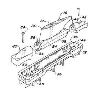
A complete lifting foil assembly is illustrated
in Figure 6. The lifting foil 16 includes the wing-like
foil element 30 which is a plastic moulding having an
integrally formed cylindrical portion 32 formed to its
inner end with an elongated hinge pin 34 passing through
3~
the cylindrical element and having its opposite ends
projecting outwardly thereof. A rod element 36 welded to
hinge pin 34 at approximately right angles thereto extends
a substantial distance through -the interior of the
wing-like foil element 30 thereby providing substantial
structural strength. Stop members 38 are welded to the
outwardly projecting end portions of hinge pin 34. The
opposing ends of hinge pin 34 extend into suitable
apertures provided in the opposed retainer members 40 and
42. Retainer members 40 and 42 are provided with
angularly spaced apart shoulders 44 which engage with the
stops 38 thereby to provide the turning position and the
lifting position for each foil as illustrated in Fig. 4.
The retainers may be made from moulded plaskic or die cast
metal. They are identical except for the shoulder
arrangements 44 which make them handed parts~ It might be
noted here that the par~s providing the foil assembly with
a left hand movement are identical to the parts of a
lifting foil assembly with a right hand movement. Left
hand movement can be changed to right hand movement simply
by switching the positions of the retainers 40 and 42.
The lifting foil assembly further includes a base
assembly 46 comprising an elongated generally rectangular
plastic moulding having an elongated recess 48 ~xtending
the length thereof and sized to receive the retainers 40
and 42 and the inner end of the wing-like foil including
items 32, 34 and 38 as noted above. The base assembly
includes two threaded metal inserts 50 which are moulded
in place. The base assembly is designed to be fixed in
place in a suitably sized recess formed in the sailboard
hull. Accordingly, its bottom surface is provided with
suitable ribs 56 and channels 58 of any desired size and
shape as to provide increased surface area to be engaged
by adhesive or cement (preferably epoxy). The facing
surface 52 of the base assembly is positioned flush with
the bottom surface of the hull. Screws 54 hold the
retainers 40 and 42 in place within the base assembly 46.
When the assembly has been fitted together, the stoos 38
on hinge pin 34, in conjunction with the shoulders or
ledges 44 on the retainers 40 and 42, serve to limit the
movement of the lifting foils 1~ between the vertical
position and the angled position (preferably 45). In
other words, the angular relationship between shoulders 44
is such that the square lugs forming par~ of stops 38 are
limited, in the preferred embodiment, to angular movement
of about 45 about the hinge pivot axis which, of course,
similarly limi~s the angular movement of lifting foils 16.
EXAMPLE
A set of lifting foils has been designed for
positioning on the bottom surfaces of a sailboard in
accordance with the criteria referred ~o above. The foil
design has the following characteristics:
- length of each foil - 7 inches (17.78 cm.) (hinge
center line to tip)
20 - root chord - 4 inches (10.16 cm.)
- tip chord - 2 1/4 inches (5.7 cm.)
area of each foil ~ 18 3/4 square inches (121
square cm.)
- root section - NACA 0010
25 _ tip section - NACA 0015
The above parameters represent a conservative
approach to lifting foil design. The performance of the
NACA 4-digit series symmetrical section foil sh~pes used
are predictable and do not require great precision in
fabrication to achieve expected results. It is expected
that laminar flow sections would result in less drag but
would demand much higher precision in fabrication It is
anticipated that the performance of these types of foils
would be significantly affected in unpredictable ways by
small nicks or scratches on the foil surface. As noted
~3~()'7
- 15 -
previously, cambered foil gections could also be used.
The use of foils having a higher aspect ratio would
theoretically provide greater efficiency but could also
result in unpredictable problems such as stalling due to
twisting of the foil under heavy loadings.
The following additional comments will be of
assistance to those skilled in this art. The angular
relationships, i.e. the preferred ~5 lifting angle and
the preferred 3 angle of attack are not necessarily
optimal angles. These angles, as well as the foil
section, foil area, foil aspect ratio, foil tip shape,
foil plan form and other variables can be changed to
arrive at a better overall design. Slalom boards, wave
boards, speed boards and the like would all have differing
requirements which would have to be considered if the
optimum design for a particular board is to be achieved.
It is also noted that the structure just
described can be fitted to an existing sailboard by
cutting recesses in the hull and fastening the lifting
wing base assemblies into the recesses. If thruster
tracks have already been installed on the sailboard, they
would have to be removed or plugged before installing
these base assemblies for the lifting foil.
~y modifying the design, the lifting foils can
also be installed directly in the thruster tracks. Means
for adjusting the lifting foil hinge angles must be
provided thereby to accommodate varying thruster track
installations.
A modified design of this nature is illustrated
in Fig. 8-11. Here the lifting foil 16, of essentially
the same design as before, is freely pivotally mounted to
a pedestal 60 made of moulded plastic and having a
streamlined shape. The root end of foil 16 is provided
with a hinge pin 62 which extends forwardly into the outer
end portion of pedestal 60. Pedestal 60 has a recess 6~
:L3~3~)~
- 16 -
therein which receives a locking ring 66, the latter being
fixed to hinge pin 62 by means of a retainer pin 6~.
Interposed between the foil 16 and pedestal 60 is a stop
collar 70 (see Fig. 9) which surrounds hinge pin 62. Stop
collar 70 is keyed into the pedestal by a pair of tangs 72
on one face, and on the other face angularly spaced
shoulders 74 are provided which cooperate with a lug
formed on an annular stop member 76 which is welded to the
hinge pin 62. Shoulders 74 and stop member 76 have the
same pivot motion limiting function as described with the
principal embodiment described previously.
The pedestal 60 is secured in the thruster track
80 of the sailboard hull by means of a socket head screw
82 (Figs. 10 and 11) which extends through the body of the
pedestal and into the slot of the thruster track 80.
Screw 82 is threaded into a nut 84 which is retained in
the retaining groove 86 of the thruster track. The nut 84
cooperates with a washer 88; both have mating radiused
surfaces on one of their faces which allows for some
pivotal adjustment of the screw 82 while still retaining
good force transmitting contact in the thruster retaining
groove 86. This allows a suitably tapered shim 90 to be
interposed between pedestal 60 and the outer face of the
thruster track (and adjacent hull surface). By using
shims of differing taper angle, the foil angle of attack,
when in the lifting position, can be changed.
The above-described modification is very useful
for fitting the lifting foils to existing sailboards etc.
The foil hinge axis defined by this modification is spaced
below the hull surface and, by virtue of the pedestal,
drag is increased somewhat; however it is still considered
to be an efficient design.
A preferred embodiment of the invention has been
described by way of example. Those skilled in the art
will realize that numerous changes may be made to the
~3~ 7
- 17 -
details of construction without departing from the spirit
or scope of the in~ention as hereinafter claimed.