Note: Descriptions are shown in the official language in which they were submitted.
1 308580 61-284,265
METHOD OF REDUCING SLAB IN WIDTHWISE DIRECTION
The integration of slab width has a remarkable
merit in the energy-saving based on the intensification
of continuously casting molds in the continuous casting
operation and the shortening of steps. Recently, it is
05 placed to synchronize the continuous casting with a hot
strip mill by unifying widths of continuously cast
slabs.
In order to unify the slab width, it is
necessary that the width of the slab can largely be
10 reduced up to a minimum product width at a hot rough
rolling process as a preliminary step. A method of
reducing slab width, which satisfies the above
requirement, wi]l be described below.
There is known a method of largely reducing slab
15 width through a large-size roll or large-size caliber
roll, which has been developed from the conventional
width reducing method through a vertical roll mill as a
width reducing adjustment.
In this method, however, the slab is largely
reduced by the roll, so that metal flows particularly at
the leading and tail ends of the width-reduced slab
toward these leading and tail ends, and consequently a
so-called crop largely grows to extremely degrade the
1 308580
yield.
On the other hand, Japanese Patent laid open
No. 5g-101,201 has proposed a continuously widthwise
pressing, wherein a slab is ~ed between a pair of press
05 tools approaching to and separatin~ from each other at a
predetermined minimum opening to gradually reduce the
width of the slab between the slant portions of the
press tools and make the slab to a given slab width
between the parallel portions of the press tools.
Particularly, Japanese Patent laid open No. 61-135,402
discloses that in order to minirnize the leading end
crop, the quantity of the leading end portion of the
slab fed between the press tools is larger than the
quantity of the steady portion, and in order to prevent
16 the dull deformation of the slab at its leading end
shoulder, the leading end portion of 50~100 mm in length
is wider than the width of the steady portion.
When the thus treated slab is rolled to produce
a hot strip coil, the dull deEormation of the shoulder
portion i5 prevented and the crop 109s becomes small,
but there is caused another problem that the strip width
is largely shortening at a position located inward from
the leading end. Such a narrow width portion is
particularly large at the leading end side and also may
be caused at the tail end side, which is cut out as a
width shortage to largely reduce the yield.
1 308580 64881-287
It is an object of the invention to provide a method of
reducing a slab in widthwise direction through a press for
producing a hot strip coil having a good width accuracy over a
whole length in longitudinal direction of the coil which
effectively prevents the rapid shortening of coil width caused at
the most leading end and the slight tail end portion of the hot
strip coil produced by rolling the slab having a width reduced
through the press tools and further the width shortage liable to
be caused at the tail end.
According to the invention, there is provided a method
of reducing a slab in the widthwise direction thereof by reducing
the width of said slab over a whole length thereof through a pair
of press tools periodically approaching to and separating away
from each other in the widthwise direction of said slab prior to
subsequent flat pass rolling at a hot rolling step of the slab to
reduce crop losses at leading end and tait end of said slab,
including the step of passing said slab through said pair of press
tools to reduce the slab wldth W in the widthwise direction so
that widths WLE and WTE, adjacent the leading and tail ends,
respectively, of the reduced steady portlon WM of said slab, are
made wider by said press tools in the longitudinal direction
thereof over a length of 150-2000 mm, which widths WLE and WTE are
called as non-steady portions, and controlling the spacing between
the press tools to provide predetermined lengths ILE and ITE f
said non-steady portions in said leading end and tail end which
are wider by a width reducing variation quantity o as compared
with said steady portion, wherein ~=a. AWo wherein a is a
1 308580
64881-287
proportionality factor of 0.8-0.9 and ~W0=WO-WM wherein W0 is a
width after flat pass rolling and WM is a width of said slab after
the pressing, wherein said lengths ILE and ITE are represented by
ILE=F(H, W, WM) and ITE=f(H, W, WM), in which H is a slab
thickness, W is a slab width and W~ is a slab width of the steady
portion after pressin~, respectively, wherein 400 mm -IIE-2000 mm
and 150 mm -ITEC-1500 mm, respectively, wherein said
O is represented by the following equation:
~ Wo=F(H, W, WM D, r), in which D is a roll diameter in flat pass
rolling and r is a reduction ratio in flat pass rolling, and
satisfies 10 mm<=0~70mm.
In practice, the end portion of the slab having a width
wider than that of the steady portion by mitigation of width
reducing quantity is made longer at
4a
1 308580
the leading end side of the slab rather than at the tail
end side, and the difference of the reduced width ~ is
usually not more than 70 mm and properly selected in
accordance with the size of the slab.
06 The invention will be described with reference
to the accompanying drawings, wherein:
Fig. 1 iS a plan view of an embodiment of the
width-adjusted slab according to the invention;
Figs. 2a to 2d are diagrammatical views showing
10 steps for reducing the slab in widthwise direction
according to the invention, respectively;
Fig. 3 is a graph showing a longitudinal width
distribution of coil produced when subjecting the width
reduced slab according to the invention or the prior art
15 to finish rolling;
Fig. 4 is a schematical view showing a plan
shape of the slab when being subjected to a flat pass
rolling after the pressing;
Fig. 5 is a transversally sectional view of the
20 slab after the pressing;
Fig. 6 is a diagrammatically plan view showing a
locally widened portion of the slab width produced when
eLE iS made too large; and
Fig. 7 is a graph showing strip lengths of width
2~ shortage portions at leading end (LE) and tail end (TE)
for various slabs whose width reduction conditions are
1 308580
given in Table l.
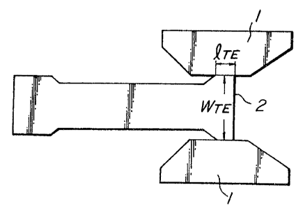
In Fig. l is shown a flat shape of a width-
adjusted slab 2' obtained by reducing the slab in
widthwise direction according to the invention, wherein
05 eLE, e~E are lengths of leading and tail end portions
from the leading and tail ends of the slab,
respectively, and WLE, WTE are slab widths at the same
end portions, and WM is a slab width at a steady
portion.
The reducing of the slab in widthwise direction
will be concretely described in the order of steps in
Fig. 2.
In Fig. 2, numeral l is a pair of press tools,
and numeral 2 is a slab at a reduced state in widthwise
15 direction,
By successively feeding the slab 2 between the
press tools l, l driven to periodically repeat the
approaching and separation, the width of the slab 2 is
reduced to a slab width WLE set by a minimum opening
20 between parallel portions l" and l" defined among slant
portions l', l' and parallel portions l", l" at the
entrance side of the press tools l, l as shown in
Fig. 2a. Then, when the leading end portion of the slab
- goes forward from the slant portions l"', l"' at the
25 delivery side of the press tools l, l to only a distance
eLE as shown in Fig. 2b, the minimum opening between the
-- 1 3085~0
press tools 1, 1 is further narrowed to a value
corresponding to a reduced width WM to perform the width
reducing of the steady portion of the slab. When the
tail end portion of the slab 2 approaches to the slant
06 portions 1', 1' at the entrance side of the press tools
1, 1 as shown in Fig. 2c, the minimum opening is again
widened to a value WTE as shown in Fig. 2d to reduce the
tail end portion in widthwise direction. In this case,
the length of the width-reduced tail end portion is eTE-
In this way, there can be obtained the width-
adjusted slab 2' wherein the widths of the end portions
shown by leading and tail end lengths eLE, eTE are wider
than the width of the steady portion as shown in Fig. 1.
When the slab is pressed from the leading end to
15 the tail end at the same minimum opening of tools
(conventional press process) and then rolled to a
thickness approximately equal to or lower than the
thickness of the original slab, the leading and tail end
portions of the slab have a plan shape as schematically
20 shown in Fig. 4. That is, the leading and tail end
portions of lengths ef and er are narrower in the width
than the steady portion. If such a slab is rolled into
a coil, the lengths ef and er are further lengthened
with the reduction of the thickness, resulting in a
26 large yield loss.
The mechanism on such a width shortage at
-7-
1 308580
leading and tail ends is considered as follows. That
is, the sectional shapes in widthwise direction of the
leading and tail end portions and the steady portion
ar~er the pressing are different as shown in Figs. 5a
o~ and 5b. The leading and tail end portions are liable
to flow metal in the lengthwise direction, so that they
indicate a single bulging ~orm wherein the widthwise
central portion is relatively thick. On the other hand,
the steady portion restrains the flowing of metal in the
10 lengthwise direction and indicates a double bulging form
wherein both side ends are thick. When this slab is
sub~ected to a flat pass rolling, portions having a
relatively thick thickness are strongly rolled, during
which metal moves in the lengthwise direction and the
lB widthwise direction. In this case, the steady portion
hardly moves metal in the lengthwise direction, 50 that
metal is easy to be flown in the widthwise direction as
compared with the leading and tail end portions.
Furthermore, the thicker portion of the steady portion
is both 9ide ends thereof, so that the width returning
is more facilitated. From this reason is caused a
phenomenon that the width of the steady portion becomes
wider, and in other words, the widths of the leading and
tail ends become relatively narrow.
2B Therefore, it is important to make the width of
the pressed slab at the leading and tail ends wider in
-` 1 308580
accordance with estimate quantities of width returning
at the leading and tail ends and steady portion.
For this purpose, it is necessary to determine the
quantity (8) and lengths (eLE, eTE) of the leading and
06 tail end portions to be pressed as compared with those
of the steady portion.
The settlement of S is based on the estimation
of width returning quantity of the steady portion when
the slab is subjected to flat pass rolling after the
10 pressing (~WO=W~_WP, wherein WO is a width after flat
pass rolling, and Wp is a width of slab after the
pressing). ~WO is determined in relation to size of
slab before the pressing (thickness H, width W), width
of slab after the pressing (Wp) and flat pass rolling
1~ conditions (roll diameter D, draft r). That is, ~WO is
represented by the following equation:
~WO = f(H, W, Wp, D, r)...... (1)
Further, ~ and ~WO to be actually measured are
empirically represented by the following equation:
8 = ~- ~WO --.- (2)
In this case, a is a proportionality factor and has a
value of 0.8~0.9. When the reduced quantity of width is
not more than 350 mm, the value of 8 is 10~40 mm in case
2~ of slabs having a narrow width of less than 1,300 mm and
20~70 mm in case of slabs having a width of more than
g
1 3085~0
1,600 mm. Furthermore, the ~ values at the leading and
tail ends are substantially the same, which can prevent
the width shortage at the leading and tail ends.
The invention will be described with respect to
06 eLE and eTE below. eLE and eTE are distances from the
leading and tail ends so that the sectional shape in
widthwise direction after the pressing becomes equal to
the shape of the steady portion, and are represented by
the following equations as functions of slab size and
10 press conditions:
eL~ = f(H, W, Wp)
} .......... (3)
~TE = f (H, W, Wp)
As a result of various experiments of eLE and eTEI the
values of eLE and eTE are eLE=400~1,500 mm and
16
~'TE=150~1,000 mm in case of narrow width slab and
eLE=1,000~2,000 mm and eTE=700~1,500 mm in case of wide
width slab. When eLE and e~E are too long, locally
swelled wide portion 5 as shown in Fig. 6 is formed in
these areas after the flat pass rolling due to the
difference of sectional shape as shown i.n Fig. 5, so
that it should be taken a care of enlarging the values
of eLE and eTE. This swelled wide portion is reduced
through vert.ical roll in the subsequent rough rolling,
but if it exceeds the rolling ability of the vertical
2~
- 10 -
1 308580
roll, the swelled portion remains as it is, or the
vertical roll may be damaged.
(Example~
The invention will be described with re~erence
05 to the following example as compared with the
conventional method.
A hot steel slab of 215 mm in thickness and
1,600 mm in width as shown in the following Table 1 was
successively fed between opposed press tools in a
10 hori~ontal type press, during which eLE~ eTEr WLE and WTE
were changed to reduce the slab in widthwise direction
up to a steady portion width of WM=1,430 mm, and then
immediately subjected to rolling in rough rolling mills
and finish rolling mills to produce a hot strip coil of
16 2-8 mm in thickness, 1,420 mm in width and 400 m in
length.
26
1 308580
._.. ..
o o o o
~, o o o o o
O ~ ~ ~r ~ ~ ~ .
r _ N N N r~
Ll ~ -- ~ E-~ ~
S ~ ~ ~ O O O O
al a~ 1-1 14rl ~ OO O O
O ~ra S 11')
~1 ~ ~ (~ QJ
3 UJ ~:1
.
i3 r~ ~ O OO O O
~ æ E, ~ ~ r
S rl
~1 ~ U~ ~ ~ O O O O O
~V rl ~) ~~ ~" .r~ Ir) ~I t~l ~) 1~)
3 ~1 ~ ~
Id ,a h tn Q~ r I r-l ~1 ~ ~1
,~ a) _ o o o oo
1-1 ~3 rl ~ et~ll7 t~ 1~ ~)
a
- ~
N U~' O O
I~ ~ . .. ______
rl ~ ~ ~ ~ N
~O~ ~
~ ~ ~ ~ m
U~
o~
s s ~ ~
~ H C
O
12
1 308580
Since the value of ~ calculated from the e~ua-
tion ~2) is 40 mm, the material of symbol A4 in Table 1
has widths WLE and WTE corresponding to a width of
1,470 mm obtained by adding ~ to the width of the steady
o~ portion, and eLE and eTE thereof are calculated from the
equation (3). In A1 and A2, WLE and WTE are srnaller than
those of A4, while WL~ of A3 is the same as in A4 but WTE
is smaller than that of A4. Particularly, the length
eLE of wide portion in the leading end portion of ~3 is
10 1.5 times that of A4. On the other hand, in the conven-
tional method, a slab (symbol B) of WLE=WM=WTE=1,430 mm
was obtained by successively reducing in widthwise
direction under such a condition that the minimum
opening is constant from the leading end to the tail
15 end. The width distribution over a whole length from
leading end to tail end in the coils A4 and B is shown
in Fig. 3. It can be seen from Fig. 3 that there are
portions not satisfying the standard width in the
leading and tail end portions of the conventional coil,
20 while the width of the material A4 becomes larger than
the standard width over the whole length. In Fig. 7 are
shown the lengths of leading end (LE) and tail end (TE)
portions not reaching the standard width in the
materials Al~A4 and B, from which it is obvious that when
26 WLE and WTE are small, the above lengths are large.
The value LE of A3 is a case that eLE is made larger
1 308580
than the value calculated from the equation ~3), so that
the swelled wide portion is caused at the leading end to
increase the loads of vertical roll at an initial stage
in the rough rolling/ while the swelled wide portion is
o~ not caused at delivery side of the rough rolling mills
to produce no width shortage of the coil.
As a result, A~ coil produced from the width-
adjusted slab ~ according to the invention can be made
into a product over the whole len~th, while in the
conventional material B, the leading and tail end
portions are cut out in a total amount of 14.8% as a
width shortage to largely reduce the yield.
The lengthwise length and width shortage
quantity at leading and tail ends in the conventional
16 method are considerably larger than the width shortage
produced in the product reduced in widthwise direction
through the vertical rolling mill of the other
conventional method, which is a phenomenon inherent to
the material reduced in widthwise direction by pressing.
20 Moreover, in the previously mentioned Japanese Patent
laid open No. 61-135,402, the portion of 50~100 mm
extending from the leading end is widely shaped by
pressing in order to reduce the crop loss through a
sheet bar, but this portion is cut out before the finish
26 rolling, which is related to crop loss in portions
outside the leading and tail ends shown in Fig. 3 and is
-14-
1 308580
entirely different from the above width shortage through
the conventional method.
Thus, the invention is an essential point that
the widths at the leading and tail ends of the slab are
05 made wider in widthwise direction than the steady
portion in order to prevent the width shortage of the
coil produced by the conventional pres~ing method over
the wide range, so that it is a matter of course that
the shaping method is not limited to the successive
10 pressing from the leading end as shown Fig. 2.
In order to prevent the width shortage through
the width reduction of the conventional press method,
the width over the whole length of the slab may be
shaped into a width WLE Of wide portion at leading end.
lG In this case, however, the width of the steady portion
after the flat pass rolling becomes too wide and the
rolling quantity in the rolling through vertical rolling
mills at subsequent process becomes large, so that there
are problems such as the occurrence of buckling,
20 overloading of the vertical rolling mills and the like.
In general, the vertical rolling mills in the rough
rolling mill train are small in the size and the
thickness is reduced as the rolling proceeds, so that
the width-reduced material upheaves in the vicinity of
26 widthwise end and forms a dogborn, which is substan-
tially returned in the width direction at the subsequent
-15-
1 308580
horizontal rolling mills and consequently the width of
the product coil becomes wider to cause the yield loss.
From this point, the length of the wide portion at the
leading and tail ends is sufficient to be 2,000 mm.
05 If the length is longer than this value~ the swelled
wide portion is caused as shown in Fig. 6.
By adopting the reducing of slab in widthwise
direction according to the invention, the width shortage
produced at leading and tail ends of the width-reduced
0 material can be prevented, so that even if the widths of
the continuously cast slahs are unified, it is possible
to largely reduce these slabs in widthwise direction by
the pressing, which has a very large merit i.n the
production Of hot strips oWing to the energy-Saving and
16 process simplification.
2~
-16-