Note: Descriptions are shown in the official language in which they were submitted.
-
1 308587
This invention relates to a novel rotary joint for
polari~ation plane maintaining optical fibers for optically
coupling polarization plane maintaining optical fibers for
5 use in heterodyne optical communications and optical f iber
gyros while maintaining the polarization plane maintaining
property.
FIG. 1 is a sectional view showing a conventional
optical rotary joint;
FIG. 2 is a diagram illustrating a polarization
maintaining fun~tion of a rotary joint of the present
invention; and
FIG. 3 is a sectional view of a rotary joint for
polarization plane maintaining optical fibers showing a
preferred embodiment of the present invention.
Such a rotary joint as shown in FIG. 1 is already known
as a rotary joint for optical fibers wherein a core, a clad
and a support are disposed in a concentrical structure.
Referring to FIG. 1, a rotary member 1 is supported for
rotation on a fixed member 2 by way of bearings. A focusing
lens 5 is provided on the central axis of rotation of the
rotary member 1, and a light sending side optical fiber 3 is
connected to the focusing lens 5. Meanwhile, another
focusing lens 6 is provided on the fixed member 2 in an
opposing relationship to the focusing lens 5 of the rotary
member l, and a light receiving side optical fiber 4 is
connected to the focusing lens 6. With the rotary joint, the
light sending side optical fiber 3 and the light receiving
side optical fiber 4 are positioned relative to each other
such that, whën a light outgoing end of the former is
rotated, the coupled amount of optical power to the latter is
~ 308587
--2--
maximum and the changing amount of such optical power is
minimum.
A rotary joint for coupling multi-core optical fibers is
5 also known wherein a prism is provided between a plurality of
rot~ry side optical fibers and a stationary side optical
fibers to be coupled such that the prism may be rotated at a
rotational speed equal to one half the rotational speed of
the rotary side optical fibers in the same direction (for
example, Japanese Utility Nodel Laid-Open No. 62-68106).
~ owever, if such conventional rotary joints for single-
core and multi-core optical fibers as described above were
used for coupling of polarization plane maintaining optical
fi~ers, the polarization plane maintaining property would be
lost. This is because, while the natural polarization axis
of the stationary side polarization plane maintaining optical
fiber is fixed, the direction of linearly polarized light
going out from the natural polarization axis of a rotary side
polarization plane maintaining optical fiber varies with
rotation of the rotary side polarization plane maintaining
optical fiber.
The present invention provides a rotary joint for
polarization plane maintaining optical fibers which
eliminates or at least mitigates the drawbacks of the prior
art arrangements descrihed above and can optically couple
polarization plane maintaining optical fibers of a rotary
system and a stationary system to each other while
maintaining the polarization maintaining property.
More particularly, a rotary joint for polarization plane
maintaining optical fibers according to the present invention
is constituted such that a polarization plane
. .
1 308587
-2a-
maintaining optical fiber of a rotary system and another
polarization plane maintaining optical fiber of a stationary
system are coupled to each other by way of a lens system
which includes a 1/2 wavelength plate that is rotated at a
rotational speed equal to half the speed of rotation of the
polarization plane maintaining optical fiber of the rotary
system in the same direction.
1 ~08587
Referring to FIG. 2, if linearly polarized li~ht
which oscillate~ in the direction of 0 with respect to
tlle fast axis of a ]./2 wave:Length plate comes into the
1/2 wavelengtll plate, then tlle slow axis component oE
linearly polarized li.gl~t aEter passing througll the 1/2
wavelength plate lags by ~ and is thus inverted in
phase. Conseque~ ly, linearly polarized light wllich
oscil.late.s in tl~e direction of -p with respect to the
fast axis o the 1/2 wavelengtll plate goes Ollt from the
1/2 wavelength plate.
Thus, if tlle natural po].arizatioll axes (fast axe5,
Eor example) oE tlle polarizati.on plane maintaining
optical fibers on the rotary side and the stati.onary
side are set coincidellt witl~ the East axi.s Oe the 1/2
wavelengtll plate upon initicll aligning operation, then
if the polarization plane maintainillg optical fiber on
tlle rotary s.ide i9 rotated by 0, the 1/2 wavelength
platc is rotated by()/2. Consequelltly, the direction of
linearly polarized li.ght wl~icll comes into the 1./2
20 wavelength plate ~rom the rotation side pol.arization plane
maintaining optical fiber becomes ~/2 with respect to the
fast axis of the 1/2 wavelength plate as seen in FIG.2, and
the direction of trans~itted light through the 1/2
wavelellgtll plate coincides wlth the di.rection o ~~/2
witll respect to the fast axi.s oE the ]./2 wavelellgth
plate, that is, with the natural. polarization axis of
the polarization plane maintailli.ng optical fiber on the
stationary side. ~ccording].y, the polarization
maintaining property is maintained in spite oE rotation
oE the polarization p].ane mailltaining optical Eiber oE
the rotary side.Likewise, wllere linearly polarized light is
to be translllitted from the polarization plane
maintaining optical fiber on tl~e stationary side to the
polarization plane maintail)ing optical Eiber on the
rotary side, the polarization maintaining property is
maintained.
1 308587
According to one aspect of the present invention, there
is provided a rotary joint for polarization plane maintaining
optical fibers which comprises a hollow fixed member, an
optical fiber collimator provided on a side wall of the
hollow fixed member, a rotary member partially received in
the hollow fixed member and rotatably provided in a coaxial
relationship with the fixed member, another optical fiber
collimator provided on the rotary member, a holder rotatably
provided between the fixed member and the rotary member, a
1/2 wavelength plate mounted on the holder, a speed change
gear mechanism provided between the rotary member and the
holder so as to rotate the holder at an angular speed equal
to one half the speed of rotation of the rotary member.
Each of the optical fiber collimators includes a
collimate lens, a polarization plane maintaining optical
fiber connected to the collimate lens, a holder with a convex
spherical seat, and a ferrule.
Outgoing light from the polarization plane maintaining
optical fiber on the fixed member side is expanded into a
parallel beam by the collimate lens, passed through the 1/2
wavelength plate, introduced into and condensed by the
collimate lens of the rotary side, and coupled to the
polarization plane maintaining optical fiber of the rotary
side.
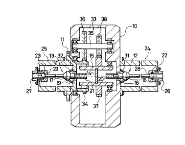
Referring to FIG. 3, there is shown a rotary joint for
polarization plane maintaining optical fibers according to
the present invention. The rotary joint shown includes a
fixed member 10 installed on a stationary system and a rotary
member 11 installed on a rotary system. ~he rotary member ll
is partially inserted in the fixed member 10 and mounted for
rotation on the fixed member 10 by means of bearings. A
1 308587
--5--
fixed side optical fiber collimator 12 and a rotary side
optical fiber collimator 13 are installed on an axis of
rotation of the rotary member 11. A 1/2 wavelength plate
holder 15 is rotatably supported on the fixed member 10 so as
to be co-axial with the axis of rotation of the rotary member
11 with a 1/2 wavelength plate 14 being supported by the
holder 15.
The fixed side optical fiber collimator 12 is a
collimator of the pigtail type including a holder 16 with a
convex spherical seat, a collimate lens 20 provided at a left
end of the holder 16 so as to face a polarization plane
maintaining optical fiber 18, and a ferrule 22 provided at a
right end of the polarization plane maintaining optical fiber
18. The ferrule 22 is mounted by means of a fastening screw
28 to a receptacle 26 installed on a receptacle holdinq
I 308587
member 24 which in ~urn is re~ovably moul~ted on the
fixed member 10.
Meanwhile, the rotary side optical fiber collimator
13 includes, similarly l-o the fixed side optical fiber
s collimator 12, a holder 17 with a convex spherical seat,
a polarization plane maintainillg optical fiber 19, a
collimate lens 21, and a ferrule 23. The ferrule 23 is
moun~ed by means of a f~s~el)in~ screw 29 I:o a r~ceptacle
27 installed on a receptacle holdirlcJ member 25 whiCh in
turn is removably mollllted Oll Lhe rotary member 11.
~ lignment of the allgles alld axe~ oE tlle Eixed and
rotary side optical fiber colLimators 12 and 13 i~
attained in tl~e followillg manl~er. The collimate lenses
20 and 21 and the polarization plane maillta;lling optical
fibers l~ and l9 are disE)c)sed in and aligned witll the
holders 16 and ~ of the fixed and rotary side optiGal
fiber collimators l2 an~ 13, respectively beforehand.
At first, the llolder 17 of the rotary slde optical
fiber collimator l3 ls presse(i at a convex s,pllerlc:al seat
against -the rotary body ll with a corlical ring
32 lnterposed therebetweel) wllile the rotary melllber 11 i~
beiny rotate~ to attain ali(Jnment o~ e collimator 13 and
the rotary member 11. ~fteI sucll an aligrment is reached,
mutually contactillg portion~ o~ the convex spherical
face o~ the holder 17 and the conical ring 32 and
mutually contacting portion~ oE the conical ring 32 and
tlle rotary member 11 are welded to each other
by, for example, irradiation oE a Y~G laser beam
upon them. It is to be rloted that they may otherwise be
fixed by soldering or the like
Subsequently, the Eixed side optical fiber
collimator l2 is aligned at -the holder 16 witll an incoming
beam with use of a convex spherical sea-t and the conical
35 ring 31, and then contacting faces of the holder l6 and the
1 308587
7-
conical ring 31 and contactil1y face of the conical ring
31 and the fixed member l0 are welded to each other by
mean~ of a Y~G laser beam.
Since tl1e diameter of ligllt beams of the
polarization plane maintail1ir-g optical fibers l~ and l9
having a small core diameter are expanded thlough -the
collimate ]en9es 20 and ~l respectively the
displacement of the optical axes oE tlle optical fibers
l8 and l9 from each otl~er is moderated signiEicantly.
Further the angular displacement can be adjusted with a
higl~ degree of accu~acy by rotatir1g the spherical
sea-ts of -the holders l6 anl l~ relative -to the conical
rings 31 and 32 respective]y.
In the meantin1e a speecl reductiol1 gear mechanism
33 for transmittil1g rotation o~ tlle rotary member ll at
a l/2 reduced angular speed in the same direction to the
l/2 wavelength plate llolder 15 is provided arollnd t21e l/2
wavelengtll plate holder 15 in the ~lxed member 1(). The
speed reduction gear mechallsm 33 includes a first gear 3
20 mounted O~1 an outer periphery of the rotary member ll a
second gear 36 moul1ted oll a sllaft 35 supported
on tl~e fixec1 me~ber l0 so as to engage with the flrst
gear 34 a third gear 37 mounted on an o~l-ter periphery
of the l/2 waveleJ1gth plate ho1del 15 and a fourth
gear 33 provided on the s~laft 35 so as to engage with
the third gear 37. lhe second and fourLh
gears 36 and 3n are each divided into two parts so that
there may be a rotatiol1al displacement between the two
parts in the direction of rotation thereof relative to
each other and a spring (not shown) is provided between
the divided gear parts oE each of the second and fourth
gears 36 and 38 so as -to exert a force to cause a
rota-tional displacement relative to each other wl1ich
elimina-tes an influence of a backlash between -the first and
35 second gears and between -the third and fourth gears.
1 308587
--U--
With the rotary ioint Eor polarization plane
maintaining optical fibers ~laving such a con~l:ruction as
described above, if light is sent out f rom the rotary
side polarized plane maintai~ lg optical fiber 19, the
5 light thus sent out i~ converted i.nto an expanded
paral.lel light by the co].limate lens 21, translllitted
through the ]./2 w~velength plate 14, introduced into and
condensed by the Eixed side collimate lens 20, and
coupled to the polarization plane maintaining optical
10 Eiber 1~. ~t the initial sel:ting, ~:he natural
polarization axes ~Ea~t axe~, ~or example) o~ tlle
polarization plane maintainirlg optical Eibers lB and 19
are made coincident witl~ the fast axis of the 1/2
wavelength plate 14.
With the arrangement, as the rotary member 11
rotates, the direction oE the llnearly polarized light
going out Erom the polar izat ion p].ane mailltaining
optical fiber 19 also rotate~ the ~ame Lime, since the 1/2
wavelength plate 14 is rotated at a speed of rotati.on
20 just equal to one half the speecl oE rotation of the
rotary member 11 togel:her with the 1/2 wavelengtll plate
holder 15, the direction of the linearly polarized light
whicll passes tllrollgh tlle 1/2 wavel.cngtll plate ~ 1 is
maintailled in a fixed stationary condition, i. e., it
25 coincides with the natural po:Larization axis of the
polarization plane mainl:aillillg optical Eiber 1~ when the
linearly polarized light is coupled to the polarization
plane maintaining optical Eiber 1~. On the contrary,
when linearly polarized light i5 sent out from the fixed
30 side polarization plane maintaining optical fiber 1
the direction of the linearly polarized light af ter
passing through the l/Z wavelengtll plate 14 is rotated,
as the 1/2 wavelength plate 14 is rotated at an angular
speed equal to twice the speed of rotation of the 1/2
35 wavelength plate 14 in the same direction. ~ccordingly,
the linearly polarized light is coupled in a coincident
1 308587
relationsllip with the natural polarization axis of the
polarization plane maintaining optical Eiber 19.
The present invention exhibits the following
efEects:
(1) Since transmission of linearly polarized light
between a rotatable po]arization plane maintaitlillg
optical fiber and a stationary polari~ation plane
maintaining optical Eiber can be performed stably on a
10 real time basis, application of t~le preserlt invention
extends to installatiorls of polarlzation plane maintaining
optical fibers for coherenl c:ommllnicatiolls and to optical
measurements. In -the measurements, signal processing out-
side the ro-tary section (i. e., on the stationary side) is
15 enabled~
(2) IE a rotary joint of tl~e present invelltion is
applied to a drawing process of a polarization plane
maintaining optical Eiber, the extinction ratio of the
polarization plane maintail~ g optical Eiber can be
measured on a real time basis.
~ 3) Where a polarizatioll plalle mailltaillilly optical
Eiber 1~ Eormed into a coil Lor use wi.tl) an op~ical
Eiber gyro or a hydroul~olle, iE a rotary joint oE tlle
present invention is apE-lied to a coiling device,
deterioration oE tl~e extillctioll ratio can be measllred on
a real time basis.