Note: Descriptions are shown in the official language in which they were submitted.
1 3 ~ 9 3
-1~ 23479-lG6
SEPARATION ~ ~I('Nu,~ ~OLID MATERIAL
This inven~ion rela~es to apparatus for separating
granular solid matter.
In particular the inventi.on is concerned wlth apparatus
which separates yranular solid material into at least three
different categories accorcling to their clensity.
In British Patent Specification No. 2,1~7,8~1 B filed by
Coal Industry (Patents) Limited, there is described a novel form
of apparatus ~7hich is of essentially tubular form and which
separates material fed into it at one encl by discharging the lower
density mater:Lal centrally along the longitudinal axis of the
apparatus and the higher density material together with the dense
medium tangentially at the other end of the apparatus. The heavy
density material is then fed to a secondary vessel having a
generally circular cross section arranged coaxially with its
longitudinal axis ancl a tangential inlet. The outlet fcr the
solid material and the dense medium is displaced from the
longitudinal axis.
There is also described in British Patent AppLication
No. 8511588 filed by Coal Industry (Patents) Limited
~.di '
1 3Q~93
2 23~79-1~6
(Publication No. 2 167 322 A) a separator means where ~he granular
solid material passes effectively between two chamber6 so that the
low density mater.ial is subje~ted to a second separating action.
It has been found that when granular mate.rial such as
coal is being separated from run of the mine dirt where the run of
the mine dirt constitutes a material having a higher specific
gravity than that of the coal to be separated the application of a
single stage of separation results in some wanted material being
~ischarged with the dirt ancl this means that there is a loss of
wanted matter. Furthermore there is often a need to separate into
three ranges of materials so that a 'Middlings' cut can be taken.
It is an object of the present invention to be able to
process the run of the mine coal to extract selectively wanted
material into three categories.
A first aspect of the p~esent invention provides
apparatus for separating solid granular material of di~ferent
densitles into at least three cateyories comprising a ~irst vessel
and a second vessel bo~h o~ generally tubular shape! the first
vessel having an axial inlet for a mlx o~ material to be separated
and a control medium, a tangential inlet remote from the axial
inlet for the introduction of a dense medlum, an axial outlet
adjacent the tangential inlet for the discharge of relatively
light density separated material, a tangential outlet ad~acent the
axial inlet for the discharge o~ relatively high density material,
the said tangential outlet of the first vessel heing connected to
a tangential inlet of the second vessel, the second vessel' being
1 30~q3
~ 23479-166
provided wlth an axial outlet adjacent the tangential inlet ~or
low density material, and a further axial outlet for relatlvely
higher density material.
The second vessel is convenien~ly a cyclone separator
wherein the lower density separa~ed material is discharged through
the top of the apparatus and the high density through the lower
end of the apparatus. Howev~r as an alternative the second vessel
may be similar to the first vessel wlth the second outlet from the
first vessel constituting the first inlet of the second vessel.
Further dense medium may be injected in~o the flow of
the separated material into the second vessel. ~his injection may
take place through a separate inlet to the second vessel which is
preferably tangential.
The discharge from the second vessel may conveniently be
fed if necessary by other means such as a crusher to be recycled
as the input to the first vessel.
A second aspect of the present inven~ion provides a
method of separating solid granular material of dl~ferent
densities into at least ~hree categories of density comprising:
feeding to a tangential inlet of a first vessel of tubular
shape a dense medium of a first specific gravity in such a manner
as to create a central vortex area extending longitudinally of the
vessel,
feediny to an axial inlet of the first vessel a mix of
makerlal to be separated,
dlscharging from an axial outlet relatively light density
separated material,
~'1
' '~
1 3~5q3
~ , 23479-166
discharging from a tangential outlet relatively high density
material into a second vessel wherein the relatively high density
material is further separated into two further ratios of specific
gravity, and
feeding to the axial inlet of the first vessel a control
medium with the mix of material in order to control the ratio of
specified gravities of materials to khe outlets.
In order that the inventlon may be readily understood
one example of apparatus for separating solid granular material
will now be described with re~erence to the two figures of the
accompanying drawings. Fiyure 1 shows a schema~ic illustration of
the apparatus and Figure 2 shows a diagrammatic end elevation of
Figure 1.
The apparatus in this particular application is for
saparating coal from dirt in a mixture which is direc~ly received
as run of the mine output.
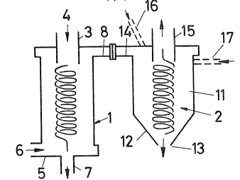
Referring now to the drawings the apparatus comprises
kwo vessels 1, 2. The first vessel 1 is of generally tubular form
and has an axial inlet 3 at its top end into which the run of mine
material is fed in direction of the arrow 4 together with
~ 3n~3
-- 5 --
a control medium.
An inlet 5 at the lower end of the vessel 1 is for a
dense liquid medium to be injected in a tangential mode. The
liquid dense medium 6 creates a vortex within t~e vessel l.
Ihe vessel l has tw~ outlets a lcwer outlet 7 whi¢h is lying
along the longitudinal axis of the vessel l and a second outlet
8 which is at the top of the vessel l and is tangential thereto.
The inlet 3 extends below the level of the outlet 8 to
ensure that none of the material 4 which is fed in is
accidentally transferred straight into the outlet 8 without
being separated.
The second vessel 2 is a cyclone separator of
oonventional design. Ihis comprises an upper part ll d a
generally cylindrical cross section connected to a conical
lower part 12 which tapers to an outlet 13. The cylindrical
upper part has a tangential input 14 which is connected
directly to the seoond outlet 8 of the ~irst vessel l. 1he top
of the second vessel 2 has an outlet 15 ~hich is axially
arranged.
In operation the dense liquid medium 6 is fed into inlet
5 and creates the vortex a10ng the centre line of the vessel
l. A mixture of a control medium and material to be treated is
fed into inlet 3 in the direction of arrcw 4 where it is caught
up in this vortex and the more dense particles are thrown to
the separator wall and pushed upwards in the vessel until t~ey
exit via the outlet 8. Ihe less dense particles, which will be
1 3 0 ~1 6 9 3
-- 6 --
coal, will move along the longitudinal axis of the vessel 1 to
the outlet 7 and will then pass from the apparatus as separated
coal.
me denser material of higher specific gravity which
passes with the dense medium through the cutlet 8 is ~ed
directly into the inlet 14 of the vessel 2 and due to the
tangential nature of the input it swirls around the cyclone and
separates in a conventional manner so that the higher density
material will pass through the outlet 13 at the bottcm of the
separator and the low density material will pass through the
second outlet 15 at the top of the se~arator.
The use of an added control medium at 4 enables the 'cut'
of separated material to be controlled. ~he way this works is
that the medium entering ~he chamber at 6 will be o~ a certain
desired relative density~ miS, if no new mediu~ was added at
p~int 4, would naturally give a separation at a certain
relative density in the irst chamber 1 and at a higher
relative density in the second chamber 2. By adding a lawer
density medium at inlet 4 a lower relative density separation
is made in the first chamber. By addition of higher relative
densi~y medium at point 4 results in much higher relative
density separation in the second chamber.
A typical set of separation results on coal obtained from
Cotgrave Calliery and using a medium having a relative density
of 1.45 is given in the following table and re~ers to the
various inputs and outputs in the Figures.
1 30~3693
Slze Fraction ~mm) 25-0.5 25-B B-4 4-2 2 0.5 Input at 4
- _
~t % of Feed 100.00 40.1830.97 17.64 11.21 Input at 4
Feed Ash % 45.38 45.6645.13 46.63 52.20
~lean Coal Yield % 42.46 45.18 42.59 40.73 35.02 Output at 7
~lean Coal Ash % 6.12 7.41 5.27 4.72 5.53
~iddlings Yield ~ 11.93 13.88 11.36 10.72 8.44 Output at 15
~iddlings Ash %35.89 36.1235.14 36.20 37.05
Reject Yield %45.61 40.9446.05 48.55 56.54 Output at 13
Reject Ash % 84.41 84.9584.45 84.09 83.37
Clean Coal & 54.39 59.0653.95 51.45 43.46 Outputs at 7
Middlings Yield % and 15
Clean Coal & 12.65 14.1611.56 11~28 11.65
Middlings Ash %
Primary dp 1.427 1.4171.420 1.440 1.475 Density of
Primary E~m 0.028 0.0300.020 0.028 Q.049 separation
Secondary dp 1.885 1.8701.792 1.770 1.88D Density of
Secondary EFm 0.094 0.0670.070 0.091 0.111 separation
dp difference 0.408 0.4580.372 0.330 0.405 difference
. at 7 and 15
_
1 3n~,~q3
-- 8 --
Misplaced Materials ~ , _ ~ at vessel 1
% at Primary
Cut-point
1) ~btal 2.32 2.90 1.31 1.59 3O~3
2) In Clean Coal 1.20 1.37 0.57 0.46 1~31
3) In Reject 1.12 1.53 0.74 1.13 2.32
Misplaced Materials at vessel 2
% at Secondary
Cut-point
1) Total 1.45 1.20 1.10 1.44 3.57
2) In Clean Coal 0.56 0.41 0.55 0.84 1.6~
3) In Reject 0~89 0.79 0.55 0.60 1.95
l ___ _
1 30~693
From the table it will be seen how the differences in
density of the three products at points 7, 13, and 15 vary.
Further control of the differences in density separation are
obtained by altering the quantity and nature of the medium fed
in at 4 to mix with the material to be separated. Typical
dense mediu~s used can be suspensions made up of water and
magnetite, sand karytes, ferrosilicon or clays.
The use of the control medium allows a range of control
separation to be achieved at will and as can be seen from the
table the cut-off points (dp) are able to be well spread and
the separation efficiency as indicated by the Epm are
relatively gocd.
When material is separated in the vessel 1 the dense
medium itself also is subjected to some separation action and
the medium exiting through outlet 7 is of a lower specific
gravity than that exiting through outlet 8 and into inlet 14.
This difference in specific gravity may in general be
sufficient for the cyclone vessel 2 to separate effectively but
if a further selected and controlled separation is required of a
different nature a further dense medi~ may ~e fed in of a
further specific gravity. Ihis further dense medium can be fed
in in one of tWD positions as shcwn by the dotted feed lines 16
or 17. If the medium is fed in through the feed line 16 it
enters with the medium discharged from outlet 8 and is mixed on
it entry into the vessel 2. Alternatively a separate
tangential entry 17 is arranged lcwer down the vessel 2 but in
1 30gh93
-- 10 --
the cylindrical part ll thereof and medium fed through feed
line 17 is mixed at a lower point in the separator.
Ihe low density material coming through the outlet 15 of
the vessel 2 will most probably contain some wanted material
such as middlings coal which can be fed to a crusher and then
recycled in crushed form with the run of the mine material 4 at
inlet 3.
It will be appreciated that the invention can be used in
a number of ways with judicious selection of dense medium to
obtain a classification of materials whether material is in
three or re categories. Fbr more than three categories ~he
separator material is fed through a further cyclone or other
separating vessel.
The application is not limited to the separation of
material containing coal but can be used for separating other
materials.