Note: Descriptions are shown in the official language in which they were submitted.
1 30~69~
GARMENT HANGER CADDY
BACICGROUND OF THE INVENTION
This invention relates ko an improved caddy
for garment hangers, and in particular to a hanger caddy
with improved latching members.
Cameron U.S. Patent 3,868,906 and Cameron
U.S. Patent 4,340,145 (both assigned to the assignee of
the present invention) disclose two prior art garment
hanger caddies. These hanger caddies are used to
organize and retain garment hangers for storage and
shipment. They have met with considerable commercial
success, and have found acceptance in a variety of
businesses.
Hanger caddies of the type described in the
_meron patents include a tubular member and a rela-
tively stiff retainer strip that is substantially
coextensive with the tubular member. Two latching
members are mounted to the retaining strip, one on
either end, and the latching members releasably latch
the retaining strip in a raised position ~in which the
retainer strip is spaced from the tubular member to
allow garment hangers to be placed on the tubular mem-
ber) and a lowered position (in which the retainer strip
holds the garment hangers securely in place on the tub-
ular member). It has been found that the detailed
design of these lakching members is critical to a suc-
cessful product.
.
:
1 ~ ~Q ~9
-- 2
In particular, the latching member is sub-
jected to outwardly directed forces when it is com-
pressed for movemen-t between the lowered and raised
positions. These forces have in the past caused latch-
ing members to break, or to take a permanent bend.
Furthermore, if the latching members are not s~ffi~
ciently rigid, actuating forces are wasted in bending
the entire latching member rather than in depressing
the spring biased portion of the latching member.
However, increased stiffness o~ the latching
member brings with it other disadvantages. This is
because the latching member must actually be bent in a
reverse direction when the retaining strip is com-
pletely removed ~rom the tubular member. Thus, if the
latching members are to be optimized they must be made
stiff enough to reduce or eliminate the ~reakage and
bending problems of the prior art, without becoming so
stiff as to interfere with removal of the latching
members from the tubular member.
Furthermore, in both of the Came o paten-ts
discussed above the latching members are operated by
applying manual forces along the longitudinal a~is o~
the tubular member. This re~uires the user to insert
his finger or thumh into khe region between the garment
hangers on the hanger caddy and the latching members.
If the garment hangers are tightly packed on the hanger
caddy, this can be difficult.
The present invention is directed to a hanger
caddy having improved latching members that to a great
e~tent overcome the prior art problems discussed above.
S~MMARY OF THE INVENTION
This invention relates to a garment hanger
caddy of the type that comprises a stiff tubular
- 2 -
1 ~0~69~
-- 3
member, a relatively stiff retainer strip substan-tially
coextensive with the tubular member, and a pair of
latching members, each sec~lred to a respective end of
the re~ainer strip and passing through a respective
pair of openings in the tubular member to secure the
retainer strip in first and second positions with
respect to the tubular member.
According to a first feature of this inven-
tion, each of the latching members comprises a first
section which defines an end portion and a latch step
configured to engage the tubular member adjacent at
least one of the openings to limit travel of the latch-
ing member, a second section which extends through a
raspective pair of openin~s, and means for securing a
irst end of the second section to the first section
such that the first section is biased away from the
second section. The second end of the second section
is secured to the retainer strip, and means are posi-
tioned intermediate the first and second ends of the
second section for stiffening the second section
against bending away from the first section. The
stiffening mean is positioned centrally on the second
section and is spaced away from -the first end of the
second section such that the second section is stiffer
at a central portion thereof than at the first end.
As explained below, the stiffening means of
this invention provides improved stiffness to the
latching member, along with improved resistance to
breaking and bending. At the same time, this stiffening
means facilitates removal of the entire latching member
from the tubular member when desired.
According to a second feature of this inven-
tion, a garment hanger caddy of the type described above
is provided with a pair of latching members which
include first and second sections and securing means as
-- 3
1 30~69~
-- 4 --
described above. In addition, each of the latching
members defines an actuating a~sis extending between the
first and second sections, and the tubular member
defines a longitudinal axis. The actuating axes are
each oriented transversely to the longitudinal axis
such that a user can operate the latching members with-
out inserting his fingers between the garment hangers
on the garment hanger caddy and the latching members.
As explained below, this arrangement makes i-t
easier for a user to operate the latching members when
the garment hanger caddy is tightly packed with garment
hangers.
The invention itself, together with further
objects and attendant advantages, will best be under-
stood by reference to the following detailed descrip-
tion, taken in conjunction with the accompanying draw-
ings.
BRIEF DESCRIPTION OF THE DRAWINGS
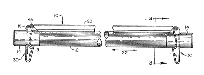
Figure 1 is an elevational view of a first
preferred embodiment of the garment hanger caddy of
this invention.
Figure 2 is a perspective view of one of the
latching members of Figure 1.
Figure 3 is a cross sectional vi.ew taken along
line 3-3 of Figure 1.
Figure 4 is a fragmentary sectional view
showing one of the latching members of Figure 1 in a
raised position.
Figure 5 is a fragmen-tary sectional view
showing one of the latching members of Figure 1 in a
lowered position.
1 30g~9g
-- 5 --
Figure 6 is a cross sectional view taken along
line 6-6 of Figure 5.
Figure 7 is a partial ele~ational view in
partial cutaway of a second preferred embodiment of th~
garment hanger caddy of this invention.
Figure 8 is a top view of one end of the
embodiment of Figure 7.
Figure 9 is a cross sectional view taken
along line 9-9 of Figure 7.
Figure 10 is a cross sectional view in the
plane of Figure 9 showing the latch.ing member in a
lowered position.
DETAILED DESCRIPTION OF THE
PRES~NTLY PREFERRED EMBODIMENTS
Turning now to -the drawings, Figures 1-6 show
a first preferred embodiment 10 of the improved hanger
caddy of this invention. The hanger caddy 10 includes
a rigid metal tube 12 and a pair of molded plastic end
caps 14. The end caps 14 are positioned in each of the
ends of the tube 12, and each of the end caps 14 defines
a respective upper opening 16 and lower opening 18. As
shown in Figures 4-6, the two openings 16, 18 are co-
linear and positioned on a diameter of the end cap 14.
The caddy 10 also includes a rigid retainer strip 20
which is arranged parallel to and substantially coexten-
sive with the tube 12. Reference numeral 22 is used in
Figure 1 to indicate a longitudinal axis which extends
parallel to the axis of the tube 12.
Tne retainer strip 20 is held in position on
the tube 12 by a pair of latching members 30. As best
shown in Figure 2, each of the latching members 30 is
integrally formed from a one-piece strip of me-tal such
as a suitable spring steel. Each of the latching mem~
bers 30 defines a free end 32, a hinge portion 34, and
1 30~698
-- 6 --
a fixed end 36. In the following discussion the por-
tion of the latching member 30 between the free end 32
and the hinge portion 34 will be referred to as the
first section 38, and th~ portion between the hinge
portion 34 and the fixed end 36 will be referred to as
the second section 40. The first section 38 defines a
latching step 42 and a depression 44 sized to receive
the thumb of a user. The second section 40 defines an
embossed ridge 46 that acts as a sti~fening means and
is positioned centrally on the second section 40 inter-
mediate the two sides thereof. Fur-thermore, this
embossed ridge 46 does not extend along the full length
of the second section 40, but is rather spaced at a
selected distance from the hinge portion 34. As
explained below, this placement for the embossed ridge
4~ makes the second section 40 stiffer a~ its center
than adjacent the hinge portion 34. This provides
operating advantages as described below. The fixed end
36 of each of the latching members 30 is secured to a
respective end of the retainer strip 20 by sui-table
securing means such as a pop rivet 48 (Figure 1).
As best shown in Figures 4 and 5, the
latching step 42 is biased into engagement with the
portion of the end cap 1~ adjacent to at least one of
the upper and lower openings 16, 18 by a spriny force
provided by the hinge portion 34. This biasing force
biases the first section 38 away from the second sec-
tion 40, and the biasing force can be overcome by
manually applied forces applied to -the first section 38
at the depression 44. Such actuating forces act to
move the first section 38 toward the second section 40
along an actuating axis designated by reference material
50 (Figure 5).
1 3"J~q~
- ~ 7 _
The latching members 30 hold the retainer
strip 20 in either a raised position as shown in Figure
4 or a lowered position as shown in Figure 5. When the
latching members 30 and the retainer strip 20 are in
the lowered posikion as shown in Figure 5, the latching
step 42 engages the end caps 14 adjacent -the lower
opening 18. When in this position the embossed ridge
46 is positioned inside the lower opening 18.
When it is desired to raise the retainer strip
20 to the position of Figure 4, the user applied
actuating forces in the direction of the arrow 50 by
placing his thumb on the depression 44 and pressing.
The embossed ridge 46 prevents the second section 40
from bending in resistance to actuating forces applied
in the direction of the arrow 50. This sti~fening
action provided by the embossed ridge 46 provides a
number of advantages. First, ik prevents the second
section 40 from bending or breaking in use. Second, it
ensures that substantially all of the energy applied by
the user acts to move the latching step 42 towards i-ts
released position, thereby reducing the forces re~uired
to release the latching member 30.
Once the first section 3a has been depressed,
the user then applies a slight upward motion to push
the latching member 30 and the reta.iner strip 20 to the
raised position shown in Figure 4. The thumb
depression 44 assists the user in applying khis raising
force, because the thumb of the user abuts against the
upper side of the depression 44 to applying raising
forces to the latching member 30.
Once the latching members 30 and the retainer
strips 20 are in the raised position o~ Figure 4, the
latching step 42 engages a portion o~ the end caps 14
adjacent the upper opening 16 to limit travel of the
latching member 30.
-- 7 --
.
1 30~1h~
On occasion, it is necessary -to remove th~ -
retainer strip 20 en-tirely from the tube 12. When this
is desired, a user simply applies forces to the second
section 40 along the ~irection of the arrow 52 in Figure
4. Because the embossed ridge 46 does not extend into
the lower opening 18 when the latching member 30 is in
the raised position of Figure 4, the second section 40
is free to bend to some extent in reaction to forces
applied in the direction of the arrow 52. This bending
compresses the first section 38 against the second sec-
tion 40, coupled with pinching 38 and 40 together at
their first ends then pulling the latching mechanisms
out of the plastic end caps thereby allowing the
latching step ~2 to pass through the upper opening 16
to release the retainer strip 20 from the tube 12. In
or~er to ~acilitate this action, the free end 32 of the
latching member 30 curves away from the second section
40. For this reason the free end 32 does not contact
the second section 40 to resist the movement of the
first section 38 re~uired to release the latching step
42 from the upper opening 16.
The garment hanger caddy 10 utili.zes latching
members 30 which are oriented as in the Cameron patents
described above with the actuating axes 50 para~lel -to
the longitudinal axis 22. Figures 7-10 show portions
of a second preferred embodiment lO' o~ the caddy in
this invention which utilizes la-tching members 30' guite
similar to the latching members 30 described above.
The main di~ference is that the latching members 30'
are rotated 90 with respect to the position of the
latching members 30 such that the actuating axes 50'
are oriented transversely to the longitudinal axis 22'
(Figures 7 and 10). This orientation for the latching
members 30' provides advantages in that the user no
longer needs to interpose a thumb or fin~er between -the
.
1 ~?¢369~
g
latching member 30' and hangers on the caddy 10'.
Instead, since the actuating axes 50' extend trans-
versely to the longitudinal axis 22', the user can
simply apply a finger or thumb to the depressions 44'
to compress the latching members 30' and move the
retainer strip 20' to the raised position.
The following details of the construction are
provided by way of illustration only in order to define
the presently preferred embodiments of this invention
in detail. In this embodiment the tube 12 is formed of
electro-tin plated steel having a wall thickness of
0.018 inch and the end cap is molded ~rom a thermo-
plastic such as ABS. The latching members 30, 30' are
formed of a s~eel such as Type C1050 having a thickness
of 0.020 inch and a width of 0.50 inch. This steel is
preferably heat treated to spring temper using the Aus-
temper process. The final product has a hardness of
44-49 (Rockwell C). The latching member 30, 30' are
finished with a black oxide finish followed by a layer
of Carnuba wax to provide a uniform surface.
From the oregoing description it should be
apparent that an improved hanger caddy has been des-
cribed that provides a number of important advantages.
First, the embossed ridge acts as a stiffening means to
stifen only desired portions of the latching member.
In this way, the latchiny member is made stiffer where
necessary to resist bending and provide easier opera-
tion. The latching member is nevertheless allowed to
bend as necessary to remove the latching member entirely
from the tube. Furthermore, the rotated position of
the latchiny member with respect to the tube ensures
that the user dose not have to insert a finger between
the garment hangers on the caddy and the latching member
itself.
~ g _ .
`I 3n~69~
I
Of course, it should be understood that a
wide range of changes and modifications can be made to
the pref~rred embodiments described above. It is there-
fore intended that the foregoing detailed description
be regarded as illustrative rather than limiting, and
that it be understood that it is the following claims,
including all equivalents, which are intended to define
the scope of this invention.
- 1 0
,