Note: Descriptions are shown in the official language in which they were submitted.
13~
Hydroponic Culture System
Background of the Invention
This invention relates to a hydroponic culture
system which provides systematic, economical, and very
workable hydroponic culture for almost uniform plants.
A conventional art hydroponic culture system
has been disclosed in Japanese Patent Publication
Laying-open No. 91833/1974. In this system, plants
are supported on an angle panel having a number of
holes; the plants are supplied with sunshine through a
transparent arch roof, and with a hydroponic solution
sprayed onto the roots of the plants from a hydroponic
solution spraying mechanism, to cultivate the plants.
The hydroponic solution spraying mechanism is fixed
inside an angle panel and is provided with a number of
spray nozzles disposed along the longitudinal
direction of the angle panel to spray the hydroponic
solution on the roots of the plants. The grown plants
are harvested by removing panels supporting the
plants.
The above-described conventional art hydroponic
culture system has disadvantages including:
(1) Since sunlight is used as it occurs naturally,
the growth rate and the harvest time of the plants
vary with climatic or sunshine conditions (duration,
direction and intensity of sunshine).
. ~
13~9G9
(2) At the harvest, the panels must be carried out
of the system and new panels must be mounted, thus
requiring a substantial time for the harvest.
(3) The entire hydroponic solution spraying
mechanism is very long and has a number of spray
nozzles, thus requiring a large amount of hydroponic
solution to be recirculated with a high supply
pressure.
(4) To assure a constant spraying pressure for each
spray nozzle, the piping design becomes complicated
and large in size.
(5) Since there is a substantial distance between
the spray nozzles, there occurs a difference in the
amount of the hydroponic solution sprayed depending on
the position of each nozzle, resulting in different
growth rates between the cultured plants.
(6) If some of the spray nozzles become clogged,
the spraying operation becomes inconsistent, and there
occurs a substantial difference in growth rate of the
plants corresponding to the clogged nozzles relative
to those corresponding to the normal nozzles.
13~89~ ~
The use of artificial light has been considered to
cultivate the plants with a uniform growth rate; however,
this method requires a large amount of photo-energy since
the lighting efficiency is low, which is impractical from
the economical point of view.
Summary of the Invention
With a view to obviate all of the conventional art
hydroponic culture systems, it is a primary object of the
present invention to provide a hydroponic culture system
which can cultivate plants almost uniformly with improved
economy and workability.
In accordance with the present invention which attains
the above object, there is provided a first embodiment
hydroponic culture system comprising an angle panel having
an angular cross section with a plurality of holes for
supporting plants with roots projecting through the holes,
and a hydroponic solution feeding mechanism comprising a
hydroponic solution spraying mechanism for supplying a
hydroponic solution onto the roots of the plants and a
hydroponic solution pumping mechanism for ~upplying the
hydroponic Yolution to the hydroponic Yolution spraying
mechanism. The spraying mechanism i~ movable along a
longitudinal direction of the angle panel, and the Yy~tem
further compriYes a driving means for moving the spraying
13~g~ g
mechanism along the longitudinal direction. The
driving means is mounted on the hydroponic solution
spraying means. First and second position detecting
means is provided for detecting the position of the
hydroponic solution spraying means. The first
position detecting means is disposed at both ends of
the row of the angle panels and the second position
detecting means is disposed on the hydroponic solution
spraying means.
A second embodiment aeeording to the present
invention is a hydroponie eulture system comprising an
angle panel arranged in a plant cultivation strueture,
the angle panel having a plurality of holes for
supporting plants with roots projeeting through the
holes, and a hydroponic solution feeding mechanism
comprising a spraying meehanism for supplying a
hydroponic solution onto the roots of the plants and a
hydroponie solution pumping meehanism for supplying
the hydroponie solution to the hydroponie solution
spraying meehanism. This system further eomprises an
environment eontrol means eonsisting of a measuring
deviee for measuring the eoneentration of earbon
dioxide in air sampled in a duet means for eondueting
air between a spaee defined by the plant eultivation
strueture and an air-eonditioning unit. The system
also eomprises a earbon dioxide outlet port eommuniea-
ting with the duet means, a earbon dioxide supply duet
eonneeting the earbon dioxide outlet port and a carbon
dioxide supply souree and having an eleetromagnetie
valve, and a eontrol means for eontrolling the
eleetromagnetie valve in dependenee on the concentra-
tion of carbon dioxide measured by the carbon dioxide
concentration measuring device, whereby the coneentra-
-- 4
'` `~ L~
- 13~ 9
tion of carbon dioxide in the space defined by the
plant cultivation structure can be adjusted to a
predetermined value.
The third embodiment according to the present
invention is a hydroponic culture system comprising an
angle panel having a plurality of holes for supporting
plants with roots projecting through the holes, and a
hydroponic solution feeding mechanism comprising a
hydroponic solution spraying mechanism for supplying a
hydroponic solution onto the roots of the plants and a
hydroponic solution pumping means for supplying the
hydroponic solution to the spraying means. The angle
panel is disposed within a p]ant cultivation structure
shielded from sunlight, the system further comprising
a lighting apparatus for irradiating the plants
supported on the angle panel, and a control means for
controlling the environment within the plant
cultivation structure. The environmental control
means has a carbon dioxide concentration measuring
means for measuring the concentration of carbon
dioxide in air sampled in a duct means for conducting
air between a space defined by the plant cultivation
structure and an air-conditioning means. A carbon
dioxide outlet port means communicates with the duct
means. A carbon dioxide supply duct means connects
the carbon dioxide outlet port means and a carbon
dioxide supply means and has an electromagnetic valve
means. Control means is provided for controlling the
electromagnetic valve means in dependence on the
concentration of carbon dioxide measured by the carbon
dioxide concentration measuring means, whereby the
concentration of carbon dioxide in the space defined
by the plant cultivation structure can be adjusted to
a predetermined value.
~`~
~, L~, :~ -
~31rt8~ 9
A fourth embodiment according to the present
invention is a hydroponic eulture system comprising a
plurality of angle panels arranged in a plurality of
rows within a plant cultivation structure shielded
from sunlight, each of the angle panels comprising two
panels with upper edges joined, each panel having a
plurality of holes for supporting plants with roots
projecting through holes, and a hydroponic solution
feeding mechanism comprising a spraying mechanism for
supplying a hydroponic solution onto the roots of the
plan'cs and a pumping means for supplying the
hydroponie solution to the hydroponic solution
spraying mechanism, the
- 5a -
, i .~,,,:
13~,8~9
system further comprising canopies for connecting top edges
of the angle panels of adjacent rows, thereby forming
substantially triangular-sectioned spaces between adjacent
angle panels, lighting apparatus for irradiating the plants
supported on the angle panels and exhaust ports, both
disposed on a lower surface of the canopies.
The angle panel used in the present invention can be
any type of convex-sectioned panel such as that having an
angular cross section, an arch cross section, or a
trapezoidal cross section.
Brief Description of the Drawings
Fig.1 and Fig.2 are ~chematic views showing a first
embodiment of the hydroponic culture system according to the
present invention.
Fig.3 is a schematic view showing a hydroponic feeding
mechani~m and a hydroponic solution spraying mechanism
driving means for the first embodiment according to the
present invention.
Fig.4 is a schematic sectional view taken along the
arrow in Fig.3.
Fig.5 is a schematic view showing a hydroponic
cultivation factory using the first embodiment of the
hydroponic culture system according to the present
invention.
13~
Fig.6 and Fig.7 are schematic views showing a
hydroponic solution feeding mechanism and a hydroponic
solution spraying mechanism of a second embodiment of the
hydroponic culture system according to the present
invention.
Fig.8 and Fig.9 are a front view and a side view,
respectively, of a hydroponic solution spraying mechanism of
a third embodiment of the hydroponic culture system
according to the present invention.
Fig.10 and Fig.11 are a front view and a side view,
respectively, of a position detecting means of the second
embodiment according to the present invention.
Fig.12, Fig.13 and Fig.14 are schematic views showing a
fourth embodiment of the hydroponic culture system according
to the present invention.
Fig.15 and Fig.16 are schematic views showing test
examples in the fourth embodiment according to the present
invention.
Fig.17 through Fig.l9 are schematic views showing an
environment control means of a plant cultivation structure
using a fifth embodiment of the hydroponic culture system
according to the present invention.
Fig.20 through Fig.22 are schemstic views showing a
hydroponic culture system according to the conventional art.
13~J~9~9
Detailed Description of the Invention
Preferred embodiments of the present invention when
applied to a hydroponic culture system will be described
with reference to the drawings.
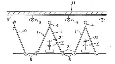
A first embodiment of the present invention will now be
described with reference to Fig.1 through Fig.5. Fig.1 and
Fig.2 are schematic views showing the structure of the first
embodiment. Referring to the figures, angle panels 1 have a
number of holes 2 which support young plants with their
roots hanging down inside the angle panels. Wheels 3 are
provided under t,he angle panels to allow movement of the
panels. The angle panels 1 are made of foamed synthetic
resins such as foamed polystyrene and earthenware stuff. As
shown in Fig.2, a plurality of the angle panels 1 are
disposed in rows, to be movable in the longitudinal
direction of the row. In this embodiment there are provided
grooves 6 which guide the wheels 3. For increased
stability, a supporting bar 5 penetrating supporting members
4 disposed at the top of the angle panels 1; however, such a
guiding mechanism for the angle panels is not always
necessary. The angle panels 1 are di~posed in a plurality
of rows as shown in Fig.l.
Next, a hydroponic solution feeding mechanism and a
hydroponic solution spraying mechanism driving means for
this embodiment will now be described. Referring to Fig.3,
13~
the mechanism of this embodiment has a hydroponic solution
spraying mechanism 7 and a pumping mechanism consisting of a
flexible hose 20 and a hydroponic solution feed pump 12. In
this case, the spraying mechanism 7, which is provided with
four spray nozzles 31, is located inside the angle panels 1
and is movable in the longitudinal direction of the angle
panels 1. The spraying mechanism 7 is connected to the feed
pump 12 with the flexible hose 20. The spraying mechanism 7
has a base plate 32, a stand rod 33 disposed standing on the
base plate 32, and two rods 34 fixed perpendicularly to the
stand rod 33, and the spray nozzles 31 are disposed on the
rods 34. As shown in Fig.4 showing a sectional view along
arrow A, these spray nozzles 31 are disposed symmetricallY
about the longitudinal direction of the angle panels 1.
Specifically, the spray nozzles 31 are disposed on the rods
34 through blocks 35 so that the spraying angle can be
flexibly adjusted. Further, the spray nozzles 31 have
adjusting screws 31a which can be turned to adjust the
amount of hydroponic solution to be sprayed.
The driving means for the spraying mechanism consists
of endless driving chains 13 and a drive motor 14 to drive
the chain 13. The Qpraying mechanism 7 is placed on two
endles~ driving chains 13 which are supported by two rolls
15 and an auxiliary rolls 16. The endless driving chains 13
are driven reciprocally or reversibly by the variable-speed,
13t~91~9
reversibly-controlled drive motor 14, which is switched to
forward or reverse movement by detection switches 18
disposed at both ends.
The flexible hose 20 is contained in a bellows holder
(not shown~ disposed parallel to the endless driving chains.
The hose can be bent only in a vertical plane parallel to
the endless driving chains 13, but cannot be bent
horizontally (in the direction perpendicular to the
longitudinal direction of the angle panels 1), so that the
flexible hose 20 does not obstruct the reciprocal movement
of the hydroponic solution spraying mechanism 7.
To spray the hydroponic solution onto the plants, the
feed pump 12 is operated to pump the hydroponic solution in
a hydroponic solution tank 19. To begin spraying from the
spray nozzles 31 the drive motor 14 is operated to begin
reciprocal movement of the hydroponic solution spraying
mechanism 7. This provides uniform spraying of the
hydroponic solution over the entire roots of the plants
inside the panels. In this case, when both ends in the
longitudinal direction of the angle panels 1 are closed, an
almost closed spraying room is formed inside the angle
panels 1, which is filled with hydroponic solution mist,
thereby providing uniform spraying.
In this embodiment, the grooves 6 which guide the
wheels 3 of the angle panels 1 can collect the hydroponic
-- 10 --
13C?~39G;9
solution on the floor, thuq providing a very improved
economy of the apparatus.
All the angle panels 1 arranged in a plurality of rowq,
which are provided inside with the above-described
hydroponic solution feeding mechanism, are disposed in a
plant cultivation structure 11 which is shielded from
sunlight. The wall material of the plant cultivation
structure 11 is not specified, but can preferably be made of
a heat insulating material; the ceiling is provided with
lighting apparatus 8 to qupply the plant with a constant
intensity of light. The lighting apparatus can be a sodium
lamp or a mercury lamp. Since this embodiment cultivates
the plants only using an artificial light, plants of uniform
quality can be systematically cultivated. In such an
arrangement, light from the lighting apparatus 8 must be
efficiently utilized to reduce the number of the lighting
apparatus 8 for reduced power consumption and improved
economy. In this embodiment, a reflector 9 is disposed on
the ceiling and a reflector 10 on the surface of the angle
panel 1 to reflect light from the lighting apparatus 8 to
the plants, thereby considerably improving the economy. The
reflectors 9 and 10 can be made of any reflective material
such as stainless steel plate or aluminum foil. The angle
panels 1 can also be made of a reflective material such as
stainlesq ~teel plate.
13~89¢~9
This embodiment uses an environment control means to
control the temperature, humidity and carbon dioxide
concentration in the plant cultivation structure 11. A
preferred example of the environment control means will be
described in detail later in another embodiment. !'
The functions and operation of the first embodiment of
the present invention with the above-described arrangement
will now be described. Young plants of a green vegetable
such as lettuce, Brassica Rapa var. pervidis, chrysanthemum
coronarium, spinach, or honewort are inserted into holes 2
of the angle panels 1. The plants are irradiated with a
specified intensity of light from the lighting apparatus 8,
and sprayed with a specified amount of hydroponic solution
from the hydroponic solution spraying mechanism 7. The
hydroponic solution is sprayed while the spraying mechanism
is moved reciprocally in the longitudinal direction of the
panels by the operation of the drive motor 14, thus spraying
the hydroponic solution evenly over the entire root parts of
the plants inside the panels.
By the above-described operation, the young plants are
systematically grown to almost uniform sizes and harvested.
Since the angle panels 1 are disposed in rows, and are
movable and detachable, the angle panels 1 with new young
plants are inserted from one end of the row, for example,
and moved successively in a direction; and grown plants can
- 12 -
13~9~9
be taken out together with the angle panels 1, thereby
considerably improving the working efficiency. Thus, when
the plants are to be grown for 20 days up to the harvest,
and 20 angle panels 1 are arranged in a row and are moved by
the length of a single panel per day, it takes 20 days from
the insertion of an angle panel 1 into one end of a row
until it comes out of the other end, and the planti on that
angle panel 1 are sufficiently grown during the period. In
this case, the angle panels 1 can be moved manually, or with
a drive unit when an increased number of angle panels are
used. In addition to the improvement in the working
efficiency, by moving the angle panels 1, the lighting
conditions (amount and direction) and the hydroponic
solution feeding conditions can be maintained consistently.
Fig.5 is a schematic view showing a hydroponic
cultivation factory using the above-described hydroponic
culture system. This factory has a structure to block
sunlight, and is provided with lighting apparatus in the
factory. As shown in the figure, the factory has 12 rows of
the angle panels 1, from 101 to 112, which can be moved to
the left in the figure. The factory also has seedling
culture rooms 120 to prepare the young plants to be inserted
into the hole 2 of the angle panels 1, a hydroponic solution
sterilizer tank 121 and an underground tank 122. Further,
the above-described hydroponic feeding mechanism i~
131~ 9
connected to a hydroponic solution sterilizer tank 125, a
pressure tank 124, and an underground storage tank 123, all
being separately disposed. The hydroponic solution is
periodically sprayed from the spray nozzles 31 of the
spraying mechanism 7, and the hydroponic ~olution sprayed
and accumulated on the floor is collected through the groove
6 shown in Fig.1. In the factory with such an arrangement,
young plants prepared in the seedling culture rooms 120 are
inserted in the holes 2 of the angle panels 1, which are
then mounted on the right side of a row of the angle panels
1, at the right side in the figure. The young plants, being
periodically moved with the angle panels 1 to the left in
the figure, absorb carbon dioxide and oxygen in the
atmosphere while being provided with the hydroponic solution
and artificial light. In this case, the carbon dioxide can
be supplied during the lighting period at which the
artificial light is applied to activate the photosynthesis.
The operation of the factory is scheduled so that the
plants are sufficiently grown when they reach the left end
of the row. The thus grown plants are removed with the
angle panels 1 from the row and collected via a panel
conveyor 126 to a panel storage 128, where the plants are
harvested, selected through a selection conveyor, and
automatically packaged for shipment. The empty angle panels
are fed by a return conveyor to the right in the figure for
- 14 -
13~ 9
use with new young plants.
As described above, with the hydroponic culture system
according to the invention, the insertion and harvesting can
be carried out at both ends of the factory (right and left
sides in the figure) with a very high efficiency. This
arrangement also enables periodical and systematic shipment
of the plants.
In the above-described first embodiment of the present
invention, the angle panels 1 are disposed movably and
detachably in straight lines, thereby considerably improving
the working efficiency of the insertion and harvest of the
plants. Moreover, moving the angle panels 1 periodically in
a direction provides almost constant lighting conditions and
systematic harvest of uniformly grown plants. In using the
artificial light together with reflecting surfaces on the
ceiling, walls, and floor of the plant cultivation structure
for effective utilization of the light, the number of the
lighting devices can be reduced, resulting in a reduction in
power cost and a considerable improvement in economy.
A variety of structures can be considered for the
hydroponic solution spraying mechani~m 7, and any structure
can be used that allows uniform spraying of the hydroponic
~olution over the entire plants according to the size and
configuration of the angle panels 1.
Furthermore, the hydroponic solution spraying mechanism
- 15 -
13~ `9
driving means and the pumping mechanism are in no way
limited to those described above; a variety of other
configurations can also be used.
A second embodiment of the pre~ent invention will now
be described with reference to Fig.6 and Fig.7. Referring
to both figures, in this hydroponic solution spraying
mechanism driving means, a spraying mechanism 7a having a
moving rollers 36 is reciprocally moved by winding a rope
23, attached to the front and rear ends in the moving
direction, with a variable-speed, reversibly-controlled rope
winding unit 21. In this case, the flexible hose 20
connecting the hydroponic solution feeding pump 12 and the
hydroponic solution spraying mechanism 7a is wound with a
hose winding unit 22 which prevents slack in the flexible
hose 20 so that it does not obstruct the reciprocal movement
of the spraying mechanism 7a. A hydroponic solution
collection groove 24 is disposed along the route of
reciprocal movement of the spraying mechanism 7a.
A third embodiment of the present invention will be
described, with reference to Fig.8 through Fig.11.
Referring to the figures, rail~ 142 are disposed on the
floor inside an angle panel 141, along the longitudinal
direction of the angle panel 141, and a hydroponic solution
~praying mechanism 7b with a self-propelling means is
disposed on the rails 142.
-- 1~ --
13~&`9~
The spraying mechanism 7b consists of a base plate 144
with wheels 143 placed on the rails 142, a stand 145
provided on the base plate 144, and spray nozzles 146
attached on both sides to the stand 145. The base plate 144
also has a variable-speed, reversible drive motor 147. A
sprocket 148 is mounted on the rotary shaft of the drive
motor 147, and the upper surface of the sprocket 148 is in
engagement with a chain 149 which is disposed along the
longitudinal direction of the angle panel 141, thus
providing the self-propelling means. The chain 149, with
both ends fixed, can be lifted up only at the part enga8ing
with the sprocket 148. Auxiliary sprockets 150 are disposed
at the front and rear sides of the sprocket 148 to prevent
excessive lifting of the chain 149.
A hanger rail 151 is provided at the top of the angle
panel 141, along the longitudinal direction of the angle
panel 141. The hanger rail 151 ha~, hung thereon, a
flexible hose 153 and a power cord 154, through hanger rolls
152. One end of the flexible hose 153 is connected to spray
nozzles 146 through the qtand 145, and the power cord 154 is
connected to the drive motor 147. There are provided a
plurality of hanger rolls 152 with adequate spacings, which
guide the flexible hose 153 and the power cord 154 along the
hanger rail 151 according to the move~ent of the hydroponic
solution spraying mechanism 7b. The other end of the
- 17 -
13~ 9
flexible hose 153 is connected to a hydroponic solution
feeding pump, which is not shown, so that the hydroponic
solution is fed to the spray nozzles 146 through the hose
153. The other end of the power cord 154 is connected to a
power supply, which is not shown, and the movement of the
spraying mechanism 7b is controlled by signals from position
detecting means provided at both ends of the rails 142.
Thus, as shown in Fig.10 and Fig.11, there are provided
proximity switches 155 which sense metals at both ends of
the rails 142, and a proximity ~witch striker 156 made of a
metal at the side of the base plate 144. When the spraying
mechanism 7b is detected at one end of the rails 142 by one
of the proximity switches 155, the phase of the alternating
current supplied to the drive motor 147 is switched to
reverse the rotation of the drive motor 147, thereby
reciprocally moving the spraying mechanism 7b. The
proximity switches 155 used in this embodiment are resistant
to water and therefore preferable for use as the position
detecting means, however, this apparatus is in no way
limited to such proximity switches, and other types such as
limit switches or photoelectric tube~ can be used.
The third embodiment of the hydroponic culture system
with the above-described arrangement according to the
present invention is used as follows. Young plants such as
of lettuce are inserted into the plurality of holes provided
- 18 -
13~
in the angle panel 141, and irradiated with light from the
lighting apparatus (not shown). Then the drive motor 147 is
energized to rotate the sprocket 148, which engages with the
chain 149 to move the base plate 144 along the rails 142.
When the base plate 144 reaches one end of the rails 142 and
is detected by the proximity switch 155, the drive motor 147
is rotated in rever~e to move the base plate 144
reciprocally. At the same time, the hydroponic solution is
sprayed from the spray nozzles 146 evenly over the roots of
the plants. The flexible hose l53 and the power cord 154
are automatically extended and contracted according to the
movement of the base plate 144 by the function of the hanger
roll 152, thus preventing obstruction to the reciprocal
movement of the base plate 144.
The self-propelling meanQ in this embodiment conSistQ
of the drive motor 147, the sprocket 148, and the chain 149.
Since the chain 149 is disposed only one on the floor, there
is no difficulty in adjusting the tension of the chain 149,
and since there are also provided the auxiliary sprockets
150, the chain 149 and the sprocket 148 will not disengage.
The self-propelling means is in no way limited to the type
as described above; any types may be used that positively
move the hydroponic solution spraying mechanism 7b in
reciprocal movement.
A fourth embodiment of the present invention will be
-- 19 --
ns~
described with reference to Figs.12 through 16. Referring
to the figures, there are provided angle panels 203 in a
plant cultivation structure 201, each consisting of two
panels 203a with the top edges joined, arranged in a
plurality of rows, and having a number of holes to support
plants 202 where the roots are projected inside the panels
203a. Both endQ of the rows of the angle panels 203 are
connected to side walls 201a. Top edges of the adjacent
angle panels 203 are connected with canopies 204 having an
angular cross section to prevent diffusion of light to the
upper side, forming nearly triangular-sectioned spaces
surrounded by the adjacent angle panels 203 and the canopies
204. An exhaust duct 205 as an exhaust means is provided at
the center of the canopy 204, and lighting apparatus 206 are
disposed under the exhaust duct 205, which are arranged with
nearly equal spacings along the longitudinal direction of
the angle panels 203.
The angle panels 203 can be made of foamed polystyrene,
stainless steel, reinforced plastics, or ceramics, and have
an inclination angle of 40 to 70 degrees, preferably 60
degrees, from the horizontal plane in view of the
cultivation and lighting efficiencies. The canopies 204 can
also have another cross section, other than the angular
crosQ section, such as an arc cross section that may provide
concentration of heat to a limited position under the
- 20 -
13~
canopies and improved exhaust efficiency, and preferably be
made of a heat-insulating material such as foamed
polystyrene, or the heat-insulated material bonded with a
reflecting material such as stainless steel plate or
aluminum foil.
The lighting apparatus 206 consists of a lamp 206a such ~'
as a sodium lamp or mercury lamp and a cover 206b, and an
exhaust port 207 communicating with the exhaust duct 205 is
formed between the lamp 206a and the cover 206b. The cover
206b is to prevent diffusion of the radiation heat of the
lamp 206a, and can be made of a transparent material. The
exhaust duct 205 communicates with a duct 208 outside the
plant cultivation ~tructure 201, and heat in the cultivation
space is exhausted by a ventilation fan 209 disposed in the
duct 2Q8. The side wall 201a of the plant cultivation
structure 201 is provided with an air supply port 210. The
air supply port 210 is to introduce the outside air, and can
also be connected to an air-conditioning unit to supply cold
air to the cultivation space or carbon dioxide when such i~
in short supply. The duct 208 and the air supply port 210
can also be connected to the same air-conditioning unit to
recirculate the air. In this case, it is sufficient to
replenish the amount of carbon dioxide absorbed by the plant
202, thus providing improved economy. Although it is
preferable that the side wall 201a is provided with the air
supply port 210, both ends of the rows of the angle panel~
213 can be opened instead.
There is provided a hydroponic solution spraying
mechanism 211 inside the angle panels 203, to feed the
hydroponic solution or the like to the roots of the plants
202. The spraying mechanism 211 is connected to a pump (not
shown) with a polyvinyl chloride pipe to pump the hydroponic
solution stored in a hydroponic solution tank 212 which is
disposed underground outside the plant cultivation
structure. The pump and the polyvinyl chloride pipe form a
hydroponic pumping mechanism of this embodiment.
The spraying mechani~m 211 can be as shown in the first
to thira embodiments described above. In this embodiment,
the hydroponic solution sprayed and accumulated on the floor
is collected through a collection passage 213. The inner
surface of a ceiling 201b of the plant cultivation structure
201 i~ provided with a heat-insulating material 214.
In this arrangement of the hydroponic culture system,
the surface of the angle panels 20~ can also be provided
with a reflecting surface in addition to the lower surface
of the canopy 204 for further improved lighting efficiency.
A closed-type lighting and an open-type lighting in the
fourth embodiment are compared. The closed-type lighting
indicates one which uses the hydroponic culture system
having the canopies in this embodiment. Test systems used
are shown in Fig.15 and Fig.16, of which the components sre
indicated with the same numerals as used in the
above-described embodiment with the description omitted.
The lower surfaces of the canopy 204 in Fig.15 and the
ceiling in Fig.5 are provided with reflecting surfaces. A
940W reflector-type high-pressure sodium lamp with a total
light flux of 110,000 lumina is used for the lighting
apparatus 206.
The cultivation conditions include a daytime of 18
hours, a day temperature of 24 degrees C, a night
temperature of 18 degrees C, and a carbon dioxide
concentration of 1,500 ppm. Young plants of lettuce of 20
days after seeding (with 4 to 5 leaves, about 10 g weight)
are planted at positions A to E, and the weights of the
individual plants are compared after a cultivation of 10
days. The result is shown in the Table below.
____________________________________________ ____________________________
Position A B C D E F G H I J K Av.
_______________________________________________________________ _______ _
Closed Illuminance 1.8 2.0 2.1 2.3 2.4 2.6 2.6 2.5 2.3 2.1 1.9 2.2lighting (x 10,000 lux)
Plant wei~ht 83 89 93 86 117 93 117 122 100 88 81 97
(g)
__________,______________________________________ _________________ _ __ __
Open Illuminance 1.4 1.6 1.7 2.0 2.3 2.6 2.5 2.4 2.2 2.0 1.7 2.0
lighting (x 10,000 lux~
Plant weight 36 62 78 84 88 110 114 108 90 84 74 84
(g)
______ ___________________________________________________________________
As shown in the Table, the closed-type lighting
provides a higher illuminance on the panel surface than the
-- 23 --
open-type lighting, and a higher growth rate, resulting in a
greater plant weight.
A fifth embodiment of the hydroponic culture system
according to the present invention will be described with
reference to Figs.17 through 19. In this embodiment, a
preferred environment control means for the hydroponic
culture system is described. Referring to the schematic
view in Fig.17, a plant cultivation structure 301 has an
exhaust port 302 and an air supply port 303, which are
connected to an air-conditioning unit 304 disposed outside
through an exhaust duct 305 and an air supply duct 306,
respectively. With such an arrangement, air in the plant
cultivation structure 301 is fed by a suction fan 307
disposed in the exhaust duct 305, through the exhaust duct
305 to the air-conditioning unit 304, where the air is
conditioned (cooled or heated). The conditioned air is
returned by a blowing fan 308 through the air supply duct
306 to the plant cultivation structure 301. In this
embodiment, there is provided a carbon dioxide sensor 309 as
a carbon dioxide concentration measuring device in the
exhaust duct 305, which takes in a sample to be measured for
the concentration of carbon dioxide and outputs an
electrical signal according to the measured carbon dioxide
concentration of the sample to a carbon dioxide controller
310 as a control means. A carbon dioxide outlet port 311 is
- 24 -
13S~9G~
provided in the vicinity of the connection of the air supply
duct 306 to the air-conditioning unit 304. The carbon
dioxide outlet port 311 is connected a carbon dioxide
cylinder 312 as a carbon dioxide supply source through a
feed pipe 313 as a feed passage, and an electromagnetic
valve 314 is disposed in the middle of the feed pipe 313.
The carbon dioxide controller 310 has a function as a
control means to control the electromagnetic valve 314
according to the electrical signal transmitted from the
carbon dioxide sensor 309. Thus, the carbon dioxide
controller 310 compares the value of the electrical signal
transmitted from the carbon dioxide ~ensor 309 and an
electrical signal value corresponding to a predetermined
carbon dioxide concentration and opens the electromagnetic
valve 314 for a predetermined period of time according to
the difference between the above signals to feed a
predetermined amount of carbon dioxide into the air supply
duct 306. Amounts of carbon dioxide to be fed relative to
the difference in the electrical signals between the
measured value and the setting value are previously
determined through a test operation and set to the carbon
dioxide controller 310.
Since, in this embodiment, air is exhausted from the
plant cultivation structure 301 through the exhaust port 302
and fed through the air supply port 303, it is circulated at
- 25 -
13~1~9~9
a substantial speed in the plant cultivation structure. In
this embodiment, the exhaust port 302 iQ disposed on the
ceiling at the center of the plant cultivation structure 301
and the air supply ports 303 are disposed at both sides of
the plant cultivation structure 301, thereby providing a
high recirculation efficiency. By Qampling air in the
exhaust duct 305 for measuring the carbon dioxide
concentration in the plant cultivation Qtructure 301, a
measured value which reflects the entire plant cultivation
structure 301 can be obtained. This leads to a proper
supply of carbon dioxide according to the measùred
concentration of carbon dioxide. Since the carbon dioxide
is not directly supplied into the plant cultivation
structure 301 but is supplied from the carbon dioxide outlet
311 into the air supply duct 306, the supplied carbon
dioxide is mixed with recirculating air and then fed into
the plant cultivation structure 301. Therefore, there will
not occur an uneven distribution of carbon dioxide
concentration in the plant cultivation structure 301.
There are provided in the plant cultivation structure
301, as shown in Fig.18 and Fig.19 for example, angle panels
320 arranged in a plurality of rows (three rowQ in the
figures), each consisting of two panels 321 with the top
edges joined, having a number of holes to support plants 322
of which the roots are projected inside the panels 321.
- 26 -
13S~ 9
Both ends of the rows are connected to side walls 301a, and
both sides are closed with side walls 301c. Top edge~ of
the adjacent angle panels 320 are connected with canopies
323 having an angular cross section to prevent diffusion of
light to the upper side, forming nearly triangular-sectioned
spaces surrounded by the adjacent angle panels 320 and the
canopies 323. An e~haust duct 302 as an e~haust means is
provided at the center of the canopy 323, and lighting
apparatus 328 are disposed under the canopy 323 and arranged
with nearly equal spacing along the longitudinal direction
of the angle panels 320. There is provided a spraying
mechanism 324 inside the angle panels 320, as a hydroponic
solution feeding mechanism to feed the hydroponic solution
or the like to the roots of the plants 322. The spraying
mechanism 324 is connected to a pump (not shown) with a
polyvinyl chloride pipe to pump the hydroponic qolution
Rtored in a tank 325 which is disposed underground outside
the plant cultivation ~tructure. The spraying mechanism 324
can be as used in the first to third embodiments described
above.
The hydroponic solution sprayed and accumulated on the
floor is collected through a collection passage 326. The
inner surface of a ceiling 301b of the plant cultivation
structure 301 is provided with a heat-insulating material
327. The air supply port~ 303 are formed at both corners of
~3~9~9
the plant cultivation structure 301.
As shown in Fig.19, there is provided a seedling
culture line 332 in the plant cultivation factory 330, in
addition to the above-described cultivation lines 331, and
the seedling culture line 332 is also air-conditioned by an
air-conditioning unit 333. Thus, the seedling culture line
332 can also be controlled for the carbon dioxide
concentration ~s needed, as described above. There are
provided cooling towers 334 and 335 for the air-conditioning
units 304 and 333 outside the plant cultivation factory 330.
In the above-described plant cultivation structure 301,
it is sufficient to control the carbon dioxide concentration
only when the photosynthesis is actively carried out (when
irradiated with the artificial light from the lighting
apparatus), thus ~roviding an improved economy.
Although, in this embodiment, the air supply port 309
is disposed in the exhaust duct 305 and the carbon dioxide
outlet port 311 is in the air supply duct 306, these ports
can also be disposed in reverse.