Note: Descriptions are shown in the official language in which they were submitted.
136; ~fd~
- 1 - 13DV-09173
~NDUCTED, COUNT~RROTATING GEARLB8S
F~ONT FAN ENGINB
This invention relates to gas turbine
engines, and more particularly, to an improved turbo
fan engine with counterrotating rotors driving
counterrotating unducted front fans as well as a
counterrotating booster compressor.
BACRGROUND OF TXB INVENTION
Conventional gear-driven single rotation
turbo props are typically used at lower cruise speeds
where they provide good performance and high
efficiency. At higher cruise speeds, it is typically
required to use a ducted turbo fan to produce the
relatively high thrust required. A scaled up version
of a conventional turbo prop engine suitable for
powering an intermediate, or large sized transport
aircraft at Mach 0.7 and 0.85 cruise speeds and high
altitude would require excessively larger propeller
diameters than is conventionally possible. The
limiting factors of the single rotation propeller is
the low power disk loading and reduced efficiency at
high subsonic flight speeds.
The turbo machinery for aircraft having
propellers are generally arranged to use a speed change
gearbox in order to reduce the speed of the propeller
rotor relative to the speed of the turbine. The speed
change gearbox provides the method for a more optimum
J~
~3{ ~
- 2 - 13DV-09173
propeller tip speed for high efficiency along with a
high speed, smaller diameter turbine drive shaft and a
high speed turbine with fewer stages. However, a
gearbox and associated accessories result in a
significant increase in engine complexity, weight and
inefficiency.
Unducted, counterrotating aft engines have
been developed such as the GE 36 engine frequently
referred to as the UDF engine. Such engines are direct
driven without gearboxes. They are, however, generally
mounted on the aft portion of the aircraft fuselage.
Mounting such an aft fan engine on the swing of an
aircraft is difficult due to the engine support pylon
being forward of the large diameter fan.
OBJECT8 OF THE INVENTION
It is accordingly, an object of the invention
to provide an improved unducted, counterrotating
gearless front fan engine.
It is another object of the present invention
to provide a gas turbine engine using counterrotating
turbine sections which drive counterrotating unducted
front fans and a counterrotating booster section.
It is a further object of the present
invention to provide a gas turbine engine having a core
engine, which is essentially a gas generator; a power
turbine comprising two interdigitated counterrotating
turbine rotors aft of the core engine; two
counterrotating unducted fan blade sections forward of
the core engine; and two counterrotating interdigitized
booster compressor rotors spaced between the fan blade
sections.
Another object of the present invention is to
provide a gas turbine engine having two stationary
support frames with a gas generating core engine
supported therebetween and with the same stationary
support frames supporting counterrotating turbine
13r~Z2
- 3 - 13DV-09173
sections aft of the core engine and counterrotating
unducted fan blade sections forward of the core engine
with a counterrotating booster compressor between the
fan blade sections.
A further object of the present invention is
to provide a gas turbine engine having all of the
engine parts supported by a pair of spaced apart
stationary support frames and with the engine parts
contained within an outer casing which is not a
structural supporting member.
Yet a further object of the present invention
is to provide an unducted, counterrotating gearless
front fan engine and using either a pair of spaced
apart forward swept fans, aft swept fans, k or a
combination of forward and aft swept fans.
Still another object of the present invention
is to provide an unducted counterrotating gearless
front fan engine having a variable pitch control for
the fan blades and likewise one or more variable blade
rows on the booster compressor.
8UMNARY OF THB INVBNTION
The present invention provides turbo
machinery for a very high bypass ratio, unducted front
fan engine which does not use a gearbox between the fan
and the free power turbine and also does not use a
large number of booster and turbine stages. The engine
consists of counterrotating fan sections connected to
counterrotating power turbine rotors. The connecting
counterrotating shafts between the fan sections and the
turbine rotors pass through the center bore of a core
engine. A counterrotating booster compressor is also
operated by the same shafts. By utilizing a
counterrotating booster and counterrotating turbine
rotors, the number of booster and turbine stages can be
generally reduced by a factor of two to four for a
_ 4 _ ~ ~f~ 13DV-09173
given level of efficiency and rotor speed. Typically
such high bypass ratios are in the range of 20-35.
In an embodiment of the invention, the
counterrotating booster is positioned axially between
the counterrotating front and aft unducted fan
sections. The engine is supported by two axially
spaced apart stationary support frames including front
and rear support frames. A core engine including a
compressor, combustor and a high pressure turbine is
supported from the two stationary support frames. The
counterrotating turbine rotors are supported by the
rear support frame aft the core engine. The front
support frame supports the counterrotating fan section
and counterrotating booster compressor. An aircraft
support pylon strut extends to the engine mounts on the
front and rear support frames. An outer casing is
provided about the engine with the outer casing
providing no structural support for any of the engine
parts.
In an embodiment of the invention, variable
pitch controls are used to control the pitch of the
axially spaced apart, counterrotating fan blades. The
booster compressor can also have one or more variable
booster blade rows which are part of a ganged-variable
blade row design.
The fan blades of the spaced apart front fan
sections can either be forward swept, aft swept, or a
combination of forward and aft swept design.
BRIEF DESCRIPTION OF THE DRAWING8
In the drawings:
Fig. 1 is a perspective view showing an
aircraft supporting an engine in accordance with an
embodiment of the present invention;
Fig. 2 is a side view of the engine shown in
Fig. 1;
_ 5 _ 13~ 13DV-09173
Figs. 3A and 3B are a schematic cross section
of an unducted, counterrotating, gearless front fan
engine in accordance with one embodiment of the present
invention;
Fig. 4 is a view similar to that of Fig. 2
and showing both fan blade rows being forward swept;
Fig. 5 is a view similar to that shown in
Fig. 2 and showing the forward fan blade row being
forward swept and the aft fan blade being aft swept;
Fig. 6 is a view of the forward part of the
engine showing a long inlet centerbody, and
Fig. 7 is a view of the forward part of the
engine showing a short inlet centerbody.
In the various figures, like references
designate like parts.
DETAILED DE~RIPTION OF THE INVENTION
Referring now to Fig. 1, there is shown an
aircraft 10 supporting an engine 11 in accordance with
one embodiment of the present invention. The aircraft
10 is shown having a pair of swept back wings 13, 15.
Mounted on wing 15 is an unducted, counterrotating,
gearless front fan high bypass ratio engine 11, in
accordance with the present invention. Typically the
high bypass ratio is in the range of 20-35. It will be
noted, that such mounting is by means of a pylon 58
reaching down from the wing and supporting the engine.
Because of the presence of the front fans, the mounting
is facilitated with pylon being rearward of the large
diameter fan. This provides improved mounting
arrangements, improved balancing of the engine
appropriately from the wings, and avoids many of the
problems heretofore encountered with aft mounted fans.
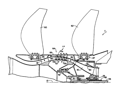
Fig. 2 shows a side view of the engine and
Figs 3A and 3B compositely show a sectional view
through the gas turbine engine 11 according to one
13~
- 6 - 13DV-09173
embodiment of the present invention. Portions of Figs.
3A and 3B overlap for ease of understanding. Engine ll
includes a longitudinal center line axis 12 and an
outer casing 14 disposed co-axially about center line
axis 12. As will hereinafter be explained in greater
detail, outer casing 14 conventionally referred to as
nacelle is nonstructural in that it does not support
any of the engine components. It can therefore be
con~tructed of thin sheet metal such as aluminum and/or
composite material.
Engine ll also includes a gas generator
referred to as core engine 16. Such core engine
includes a compressor 18, a combustor 20 and a high
pressure turbine 22, either singular or multiple
stage. The core engine 16 is modular in that it is a
single unit and can be independently replaced separate
from the other parts of the gas turbine. All of the
parts of the core engine 16 are arranged co-axially
about the longitudinal center line axis 12 of engine 10
in serial axial flow relationship. Annular drive
shafts 24A and 24B fixedly interconnect compressor 18
and high pressure turbine 22. High speed bearings 26
and 28 rotationally support the core 16.
The core engine 16 is supported on two
stationary support frames including the front support
frame 30 and the rear support frame 32. These
stationary support frames 30 and 32 (shown in Figs. 3A
and 3B) also support the other parts of the engine.
The engine components do not depend from the outer
casing 14 thereby permitting the outer casing 14 to be
a non-structural element which may be part of the
engine nacelle. The core engine 16 is effective for
generating combustion gases. Pressurized air from
compressor 18 is mixed with fuel in combustor 20 and
ignited, thereby generating combustion gases. Some
- 7 - 13DV-09173
work is extracted from these gases by high pressure
turbine 22 which drives compressor 18. The remainder
of the combustion gases are discharged from the core
engine 16 through a diffuser section 31 into the power
turbine 34.
Power turbine 34 includes an outer annular
drum rotor 36 rotatably mounted on the rear support
frame 32. The outer rotor 36 includes a plurality of
first turbine blade rows 38 extending radially inward
therefrom and axially spaced from each other.
Power turbine 34 also includes an inner
annular drum rotor 40 disposed radially inwardly of
outer rotor 36 and the first blade rows 38. The inner
rotor 40 includes a plurality of second turbine blade
rows 42 extending radially outwardly therefrom and
axially spaced from each other.
A rotating frame support 44 provides the
support for the outer drum rotor 36 and first blade
rows 38. This support in turn is carried by the rear
support frame 32. Extending from the rotating frame
support 44 is an inner shaft 46. An outer co-axial
shaft 48 is connected to the inner drum rotor 40.
Differential bearing sets 50 and 52 are disposed
between the rotating shafts 46 and 48.
The core engine 16 with its high speed
rotation forms a separate modular unit with its high
speed rotation forms a separate modular units with its
own high speed bearings. Therefore, the differential
bearings sets 50 and 52 supporting the shafts 46, 48
can be low speed bearings. The differential bearing
arrangement can include one bearing supported by the
other.
Each of the first and second turbine blade
rows, 38 and 42, respectively comprises a plurality of
circumferentially spaced turbine blades, with the first
13F; ~
- 8 - 13DV-09173
turbine blade rows 38 alternately spaced with respect
to ones of the second turbine blade rows 42. This
arrangement of blade rows of the two rotors is referred
to as being interdigitated. Combustion gases flowing
through the blade rows 38 and 42 drive the inner and
outer drum rotors 36, 40 in counterrotating
directions. Thus, the shafts 46 and 48 will also be
rotating in counterrotating directions. The shafts 46,
48 are co-axially disposed relative to the longitudinal
center line axis 12 of the engine 10 and extend forward
through the core engine 16.
At the forward part of the engine 10, there
is provided a front fan section 54. Fan section 54
includes a first fan blade row 60 connected to a
forward end of the inner counterrotating shaft 46 which
extends between the power turbine and the fan section.
Front fan section 54 includes a second fan blade row 62
connected to the forward end of the outer drive shaft
48 also connected between the power turbine and the fan
section. Each of the first and second fan blade rows
60 and 62 comprises a plurality of circumferentially
spaced fan blades. Fan blade rows 60 and 62 are
counterrotating which provides a higher disk loading
and propulsive efficiency. It should be appreciated
that the counterrotating fan blade row 62 serves to
remove the swirl on the circumferential component of
air imparted by the counterrotating fan blade row 60.
The fan blades in rows 60 and 62 may be
either an aft swept or a forward swept design. Fig. 4
shows a side view similar to that shown in Fig. 2
wherein like parts are identically indicated. However,
in Fig. 4, the blades 160 of the forward blade row and
the aft blades 162 of the aft blade row are both
forwardly swept. Likewise, Fig. 5 is again a schematic
1 3f ~
- 9 13DV-09173
view similar to that shown in Fig. 2 where in like part
are identically indicated. In this case, however, the
blades 260 of the forward blade row are forwardly swept
while the aft blades 262 of the aft blade row are
rearwardly swept.
Referring back to Figs. 3A and 3B the fan
blades in rows 60 and 62 are mounted such that their
pitch angle, or aerodynamic incidence angle, can be
mechanically varied to optimize the performance of the
engine for maximum thrust or minimum specific fuel
~onsumption and/or reduced noise level. In addition,
the variable pitch mechanism 86 and 87 serve to reverse
the direction of the fan airflow for reverse thrust
purposes. Various mechanisms are possible to provide
actuation to the fan blades as is well known in the
art.
Engine 10 further comprises a booster
compressor 64. Booster compressor 64 includes an outer
annular rotor 66 which also serves as the independent
intake end of the main flow path through the engine. a
plurality of first compressor blade rows 68 extend
radially inwardly from outer rotor 66 and are axially
spaced from each other. Booster compressor 64 also
includes an inner annular rotor 70 disposed inwardly of
the outer annular rotor 66 and includes a plurality of
second blade rows 72 extending radially outwardly
therefrom the axially spaced. The first and second
compressor blade rows 68, 72 are interdigitated and are
counterrotating. The outer rotor 66 is fixedly
attached to fan blade row 62 as well as a forward end
of the outer shaft 48. Similarly, inner rotor 70 is
fixedly attached to fan blade row 60 and the forward
end of the inner shaft 46.
Each of the first and second compressor blade
rows 68, 72 comprise a plurality of circumferentially
- 10 - 13DV-09173
spaced compressor blades with the blade rows
alternating with each other. Compressor blade rows 68
and 72 are counterrotating and located in the flow
passage leading to the core engine 16.
The counterrotating booster compressor 64
provides a significant pressure rise to air entering
the core engine 16. An advantage of having the fan
blade rows and the compressor blade rows driven by the
same drive shaft is that energy is optimally extracted
from the power turbine 34. Without the booster
compressor stages being driven by the power turbine
from shafts 46 and 48, a separated compressor with an
additional shaft and drive turbine would required. The
counterrotating booster compressor 64 gives sufficient
pressure rise despite the slow fan speed. By having
compressor blade rows 68 and 72 counterrotating, a
lessor number of compressor blade rows than that
required for a single low speed compressor driven from
only one shaft is possible. The booster compressor 64
has a separate intake forward of the fan blades which
permits fan operation in the reverse glow mode without
adversely affecting operation of the booster
compressor. Substantially all (at least 80%) of the
thrust comes from the fan section 54 and only a small
portion comes from the exhaust nozzle.
At the front end of the shafts 46 and 48
there are likewise provided two sets of differential
bearings 74 and 76, of which bearing set 76 is
differential. These likewise do not support the high
speed bearing 26 and 28 about which the core engine
rotates. Rotating frame 80 comprising a pluraity of
struts having aerodynamic shape acting as blades to
compress, is provided to support the fan blade row 62
as well as the outer booster case and blades. The
rotating frame 80 is in turn supported by the
13~
- 11 - 13DV-09173
stationary support frame 30. Rotating frame 81, similarly
constructed as frame 80, is provided to support the fan
blade row 60. These frames 80 and 81 counter rotate with
respect to each other. A series of seals 78 are
appropriately provided for retaining the flow within the
engine passageways.
An important feature of the present invention is
the positioning of the booster compressor 64. In order to
reduce the noise resulting from the fan blade rows 60 and
lO 62, sufficient spacing must be provided between the fan
blade rows. The spacing should preferably be one and one
half times or more than the aero chord length of the fan
blades of the fan blade row 60. There should also be a
spacing between the blade row 62 and the pylon 58.
Preferably such spacing should be about one aero chord
length or more of the fan blades in the fan blade row 62.
The aero chord, often referred to as the pitch line chord,
is conventionally defined as the chord at a radial distance
from the root of the blade to the tip of the blade which
divides the blade into two portions of equal area.
Accordingly, the axial spacing between the fan blade
rows 60 and 62 is used for positioning of the counterrotating
booster blade rows 68 and 72. The booster compressor 64 is
therefor contained within the length of the fan blade rows
and is positioned in parallel with the air flow.
Along with the flow path through the engine, and
positioned forward and aft of the booster compressor 64 are
the forward and aft rotating frames 80 and 81,
respectively. Aft rotating frame 80 is connected to the
outer rotor 66 and rotates along with the booster
compressor blades 68 and forward rotating frame 81 is
connected to the inner rotor 70 and rotates along with the
booster compressor blades 72. In this manner, the booster
compressor 69 can be considered as a ten stage booster with
the booster sections of one blade row being identified with
the letter a and the booster sections of the other blade row
being identified with the letter k. Booster blade rows b
~3.f~ Z2
- 12 - 13DV-09173
mounted in the outer rotating case may be either a fixed
blade row or a ganged-variable blade row design. When they
are a ganged-variable blade row the booster airflow - rotor
speed relationship can be changed to provide improved engine
performance and/or increased booster operating stability
during take-off and reverse thrust operation.
By means of the variable blades of the vanes of the
booster compressor, in combination with the variable pitch
fan blades, numerous benefits can be obtained. For example,
if the fan blades are closed down by sufficiently decreasing
the pitch angle of the fan blades, we can also close down
the boosters by sufficiently decreasing the pitch angle of
the booster blades. Thus, if an ice-up condition were to
occur, we could run the rotor faster with the same pow~r
level and shed the ice simply by the speed of the blades.
Likewise, it is also possible to open up the pitch and slow
down for landing thereby having a reduced noise condition.
A feedback control system could also be included
whereby control of the fan and boosters could be
automatically controlled as a result of sensing various
conditions with respect to the gas engine. The variable
position control for the booster compressor blades could be
achieved by bringing in an hydraulic slip ring with the
hydraulic line connected to the rotor vane. Such hydraulic
lines are well known in the art. It would only be necessary
to control the outside booster rotor blades without
necessarily controlling both sets of blades on the
compressor.
Bleed doors 83 are provided in order to adjust
the pressure along the flow path. The pressure ratio to
the booster section 64 is higher than the fan pressure
ratio and the bleed doors serve to control the stall
margin on the boosters. When the bleed doors are
opened, the air dumps out behind the fan. The pumping
- 13 - 13~ 3 DV- 0 9 l 7 3
characteristics of the low pressure booster and the
pumping characteristics of the core are not the same.
They are matched up at high speed where the engine is
normally run. However, at low speed, in order to avoid
stall it is necessary to relieve the pressure to
eliminate any back pressure. Through the use of
ganged-variable booster blades there may be no need for
the bleed doors.
The forward and aft stationary support frames
30 and 32 respectively include fixed arms extending
therefrom and supporting the core engine 16. Likewise,
the power turbine 34 is supported from the aft support
frame 32 and the fan sections 54 and booster compressor
64 are supported by the forward support frame 30.
The engine components are all supported by
the two stationary support frames 30 and 32. The outer
casing or nacelle 14 is therefore non-structurally
supporting. The end exhaust system 85 continues to
rotate around the shaft 46. In this way, it need not
be supported by the outer casing. However, if desired,
the end nozzle could be separated and a structural
support could be extended between the outer casing 14
and the end exhaust system. In this case, however, it
would be necessary to provide the casing 14 with
additional structural rigidity. The engine is
supported from the pylon 58 which reaches down through
outer casing 14 through the arm 59 and mounts onto the
stationary support frames 30 and 32.
The core engine itself can typically be the
GE/NASA E3 core engine whose specifications are
available. However, since the core engine is an
integral unit by itself, it is possible to replace this
engine with other engines such as the CF6 core or the
CFM 56 core, or others.
Typically, the fan blade rows 60 and 62 will
1~3r~
- 14 - 13DV-09173
rotate at substantially the same speeds and in the
preferred embodiment may be of the variable pitch type
which can be adjusted through known techniques to
modify the speeds to desired values.
The inlet duct to the booster compressor may
be provided by either a long inlet centerbody or a
short inlet centerbody. Figure 6 shows an upper-half
view of a typical long inlet centerbody 100 and Fig. 7
shows a short inlet centerbody 10~. The long inlet
centerbody includes a long sloping front 104 with a
rise 106 and provides protection to the booster
compressor from birds and ice strikes; however, access
to adjacent aircraft doors may be restricted by the
long inlet centerbody. The short inlet centerbody
gives a wider entry 108 and a stub nose 110 under the
fan 60 and gives access to the panels.
The aforementioned engine utilizes a
counterrotating front fan section driven by a
counterrotating turbine. The fan blade rows contain
therebetween boos~er compressor stages which are used
to super charge the core engine. The number of booster
compressor stages depend upon the degree of super
charging desired. The number and size of the
counterrotating turbine stages depend upon the power
requirement and the desired level of efficiency.
Because of the direct drive arrangement, a fairly large
number of turbine stages are needed. For example the
number of stages in each rotating direction would be
between 6 and 12 and the number of aft blades may be
different from the number of forward ~lades. The core
engine consists of a compressor, combustor, and turbine
with an adequate sized center bore to accommodate the
counterrotating turbine shafts. The core engine can be
designed to have varying requirements and disk bore
stress levels which are within available means.
~ r~.~
- 15 - 13DV-09173
It is noted, that the engine is gearless and
yet a very high bypass ratio unducted front fan engine
is achieved which can provide a significant reduction
in specific fuel consumption without the complexity of
the gearbox and associated accessories. Bypass ratios
greater than 30 can be achieved and horsepowers of
greater than 50,000 possible.
It should thus be appreciated, that the
present invention is a hybrid of the two engines
previously discussed. However, it eliminates the duct
and has various other changes. It is also similar to
the UDF engine in that it uses variable fans rather
than the aft fans. Furthermore, it can include
variable van control on the booster compressors.
Such type of fan, it should be noted, is well
suited for wing mounting on a large military transport,
such as the C5 or C17. Specific fuel consumption
improvement would be about 20%.
Numerous modifications, variations, and full
and partial equivalents can be undertaken without
departing from the invention which is limited only by
the appended claims.