Note: Descriptions are shown in the official language in which they were submitted.
1 3C~q54
1 DOUBLE TWINE ARM
Background of the Invention
The present invention relates to twine dispensing mechanisms
for wrapping bales, formed in the chambers of large round
balers, with twine and more specifically relates to double twine
arm arrangements for introducing twine into the chambers of such
balers.
U.S. Patent No. 4,457,226 granted to Meiers on 3 July 1984
shows an automatically actuated and controlled twine wrapping
mechanism which employs a single twine arm driven by gearing
oscillated by an extensible and retractable hydraulic actuator
to cycle a twine dispensing end of the twine arm between
opposite sidewalls of the bale forming chamber for causing a
bale to be wrapped with spiral wraps of twine. The baler must
be stopped during the time a bale is being wrapped and
consequently it is desirable to shorten the time required for
wrapping the bale. The cycle speed of the arm may be adjusted;
however, this also adjusts the number of wraps or wrap spacing
$ of twine applied to the bale and such adjustment may not be
desirable.
Twine wrapping mechanisms employing pairs of gear-driven,
twine dispensing arms have been developed for shortening twine
wrapping cycle time. These developments are exemplified by the
mechanisms disclosed in U.S. Patent No. 4,158,331 issued 19 June
1979 U.S. Patent No. 4,167,844 issued 18 September 1979 and
U.S. Patent No. 4,253,389 issued 3 March 1981. One problem with
these designs is that they are not applicable for use with
balers having relatively narrow bale chambers since a dispensing
arm must be relatively long in order for its dispensing end to
sweep a relatively shallow arc when dispensing and the space
~ availability for mounting two arms without interfering with one
another and with other structure is lacking on a narrow baler.
Further, no way is provided for adjusting the spacing between
wraps other than by adjusting the cycle speed of the arms.
U.S. Patent No. 4,446,783 issued 8 May 1984 discloses a
twine arm assembly which overcomes the space problem, associated
with the patented devices discussed in the immediately preceding
paragraph, by mounting two dispenser tubes on a single support
arm. However, this assembly still does not provide means for
-- 1 --
1 3~954
1 adjusting the spacing of wraps of twine on the bale without
modifying the cycle speed of the arm.
Summary of the Invention
According to the present invention there is provided a
double twine arm assembly which represents an improvement over
that disclosed in the above-described U.S. Patent No. 4,446,783.
A broad object of the invention is to provide a double twine
arm adaptable for use with relatively narrow-chambered large
round balers and being operable for changing the spacing between
adjacent wraps of twine on the bale without changing the cycle
speed of the arms.
A more specific object is to provide a double twine arm
wherein a first arm is mounted for oscillating about an upright
axis and a second arm is connected to the first arm for swinging
therewith by connection means which makes it possible to adjust
the spacing between twine dispensing ends of the arms to thereby
adjust the spacing of the twine wraps applied to a bale being
wrapped.
Yet another object is to provide a double twine arm wherein
drive means is coupled to a first twine arm for pivoting it
about a first axis and a second twine arm is pivotally mounted
to the first arm and adjustably resiliently held in a desired
position relative to the first arm to thereby dispose a twine
- dispensing end of the second arm a preselected distance from the
2S twine dispensing end of the first arm.
These and other objects, features and advantages of the
present invention will become apparent to those skilled in the
art from the description which follows and from the drawings.
Brief Description of the Drawings
FIG. 1 is a schematic, right side elevational view showing
_ the double twine arm assembly in a rearwardly extending position
dispensing twine into the bale forming chamber and showing a
portion of the twine cut-off mechanism.
FIG. 2 is a front elevational view of the double twine arm
assembly showing the double twine arm in a first location from
which it moves and to which it returns during a bale wrapping
cycle.
FIG. 3 is a plan view of the double twine arm assembly shown
in FIG. 2 but in addition showing the reversing valve shifter
- 2 -
1 3 r~ -~ 9 r~ ~
rod and a dashed line second location of the double twine arm
reached just prior to operation of the shifter rod.
FIG. 4 is a right front perspective view showing the
relative positions of the individual twine arms at the time the
twine cutting knife operating lever is operated.
FIG. 5 is an enlarged, vertical sectional view of the
double twine arm taken along line 5-5 of FIG. 4.
FIG. 6 is a plan view of a portion of the double twine arm
assembly showing the "piggy-backed" twine arm in a middle
position of adjustment and indicating other possible adjustment
positions.
Description of the Preferred Embodiment
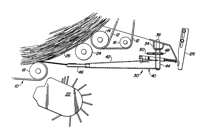
Referring now to FIG. 1, there is shown a lower forward
region of a bale forming chamber 10 of a baler for making large
cylindrical bales. The chamber 10 is of an expansible type
delimited by a plurality of belts supported side-by-side on a
plurality of rolls extending between a pair of sidewalls forming
opposite ends of the chamber and in which the ends of some of
the rolls are rotatably mounted with others of the rolls having
their opposite ends rotatably mounted in take-up or tensioning
arms vertically swingably mounted to the sidewalls. Such an
expansible bale chamber is disclosed in detail in U.S. Patent
No. 4,428,282 issued on 31 January 1984.
That portion of the chamber 10 illustrated in FIG. 1
includes a plurality of belts 12 supported in side-by-side
relationship across a driven roll 14, a roll 16 located ahead of
the roll 14 and about which only selected ones of the belts 12
are trained so as to define a staggered array, and a bottom roll
18 which cooperates with the driven roll 14 to delimit a chamber
inlet through which crop is fed by a pickup 22. A driven
starter roll 24 is located in the inlet 20 for cooperating with
the belts 12 for initiating the rolling up of crop to form a
bale core about which crop is thereafter rolled upon to form a
complete bale 26, as shown.
A double twine arm assembly 30 is shown mounted to a cross
beam (not shown) located forwardly of the bale forming chamber
10. Specifically, referring now also to FIGS. 2-4 and
considering the structure as viewed facing in the forward
direction of travel, the double twine arm assembly 30 includes a
twine arm support 34 fixed to the underside of the cross beam at
A 3
1 3 q 5 ~lr
a location rightwardly of the fore-and-aft center line of the
baler, and including right- and left-hand, upright support
shafts 36 and 38, respectively, fixed in depending relationship
to the beam. A first twine arm 40 is formed of a channel- like
main section 42 having an outwardly decreasing taper and having
an upright tubular mounting member 44 fixed to an inner end
thereof and having a generally horizontal twine dispensing tube
46 fixed to an outer end thereof. A driven gear 48 has a hub
welded to an upper end of the member 44 and the member 44 and
gear 48 are mounted for oscillation about the right-hand support
shaft 38. A drive gear 50 in the form of a toothed,
semicircular segment has a hub mounted for oscillation about the
left-hand support shaft 36. A crank arm 52 projects radially
from the hub and carries an upright pin 54 at its outer end. An
extensible and retractable hydraulic actuator 56 has its rod end
connected to the pin 54 through means of a resiliently
extensible link 58 and has its cylinder end coupled to the baler
frame by a pivot pin 60. The link 58 includes a U-shaped member
62 having its bight portion threadedly received on a threaded
end of the rod end of actuator 56. A swivel block 64 is
pivotally received on the pin 54 and carries a cross pin 66
having opposite ends slidably received in elongate slots 68
provided in opposite legs of the U-shaped member 62. A
compression spring 70 is compressed between the bight portion of
the member 62 and the block 64 and normally maintains the pin 54
adjacent the ends of the slots 66 remote from the bight portion
with the block being against a plate 67 joining the ends of the
legs of the member 62. Thus, it will be appreciated that the
link 58 will permit further extension of the actuator 56 upon
engagement of the crank arm 52 with a stop 72, the purpose of
this feature being described in more detail below.
A second twine arm 80 is mounted to the twine arm 40 for
being moved together therewith by operation of the actuator 56.
Specifically, the twine arm 80 includes a channel-like section
82 having an outwardly decreasing taper and being located
forwardly of the twine arm 40 and carrying a U-shaped bracket 84
adjacent its inner end. The bracket 84 is received between
upper and lower flanges of the channel-like section 42 of the
arm 40 and includes upper and lower legs respectively pivotally
connected to the flanges by upper and lower, axially aligned,
1 3nr~511r
1 upright pivot assemblies 86 and 88. A twine-dispensing tube 90
is fixed to an outer end of the twine arm section 82 and is
normally held spaced a preselected adjustable distance from the
twine dispensing tube 46 of the first twine arm by a spring-
loaded bar assembly 92, best shown in FIGS. 4 and 6. The bar
assembly 92 comprises a strap 94 received in an opening 96
provided in the web of the channel-like section 42 of the first
twine arm 40 and secured in,place by a bolt assembly 98 secured
in the rear end of the strap and a rivet 99 located in the strap
on an opposite side of the web from the bolt assembly 98. A
coil compression spring 100 is received on the strap 94 and has
opposite ends respectively engaged with the respective webs of
the twine arms 40 and 80. The strap 94 projects through an
opening 104 provided in the web of the channel-like section 82
of the second twine arm 80 and a cylindrical spacer 105 is
received on the strap and bears against an opposite side of the
web from the spring. A plurality of holes 106 are provided
along the length of the rod for selectively receiving a spring
wire clip 107 located ahead of the spacer, as viewed in FIG. 6,
for maintaining the arm 80 at a desired disposition relative to
the arm 40 thereby establishing a preselected spacing between
the twine dispensing ends of the arms 40 and 80 to thereby
establish the spacing of twine strands applied to the
cir,cumference of a bale being wrapped with twine. A bolt
assembly 108 in the forward end of the strap 94 prevents the arm
80 from accidentally coming off the strap when the clip 107 is
removed.
The twine arm 40 and the arm 80 carried thereby are movable
back and forth in front of the bale forming chamber between a
~ 30 first location about negative fifteen degrees (here shown as the
- full line position of the twine arms 40 and 80 in FIG. 3 wherein
the twine dispensing ends of the arms are adjacent a left-hand
sidewall 110 of the bale chamber) and a second position of about
112 degrees (here shown in dashed lines in FIG. 3 wherein the
twine dispensing ends are adjacent a right-hand sidewall 111 of
the bale chamber).
Located adjacent the left-hand sidewall 110 (FIG. 4) is a
twine cut-off mechanism 112 including a blade control rod 114
having a depending end 116 located for being engaged by an
actuator plate 118, fixed to an upper, outer location of the
-- 5 --
I 3n~954
1 twine dispensing tube 46, when the arm 40 returns to its first
location. The structure and operation of the twine cut-off
mechanism 112 is like that described in the previously
identified U.S. Patent No. 4,457,226 and for the sake of brevity
is not here described in further detail.
A bell crank 120 (FIGS. 2 and 3) forming part of a reverser
valve control linkage is mounted adjacent the right-hand
sidewall 111 for rotation about an upright pivot pin 122. A
valve shifter rod 124 has one end connected to one arm of the
bell crank and has a second end located for engagement by the
extendible link 58 upon further extension of the actuator 56
upon engagement of the crank arm 52 with the stop 72, such
further extension causing movement of the rod 124 resulting in
pivoting of the bell crank and operation of a reverser valve
(not shown) coupled for actuation by movement of the crank arm
52. Such operation of the reverser valve is like that described
in the aforementioned U.S. Patent No. 4,457,226, and for the
sake of brevity, is not further disclosed nor described here.
Suffice it to say that the actuator 56 will be caused to retract
to swing the twine dispensing arms 40 and 80 back to their first
location once the reverser valve has been actuated.
A stop 126 is positioned to be engaged by the twine
dispensing arm 80 as the arm approaches its first location. The
spring-loaded bar assembly 92 permits the arm 40 to continue
swinging once the arm 80 has engaged the stop 126, the actuator
plate 118 then passing above the arm 80 and engaging the blade
control rod end 116 to effect actuation of the twine cut-off
blade.
In operation, the twine wrapping cycle is preferably
automatically initiated, in the manner disclosed in the
aforementioned U.S. Patent No. 4,457,226, when a bale reaches a
predetermined size within the bale forming chamber 10. The
twine arms 40 and 80 are then in their first location with their
respective twine dispensing tubes 46 and 90 disposed adjacent
the left-hand sidewall 108 of the bale forming chamber 10.
Initiation of the cycle results in pressure fluid being supplied
for extending the hydraulic actuator 56, such extension
effecting rotation of the drive and driven gears 50 and 48,
respectively and in the arm 40 sweeping toward the right-hand
sidewall 110, the spring load bar assembly then acting, in
-- 6 --
1 3"~95llt
1 tension, to pull the arm 80 behind it. Once respective twine
strand ends dangling from the dispensing tubes 46 and 90 are fed
into the bale chamber along with crop fed by the pickup 22,
twine will be pulled from respective supply rolls (not shown)
and will be fed between the belts 12 and the formed bale. The
operation of the pickup 22 is then discontinued with the
rotating bale then acting to pull twine from the supply rolls.
Wraps of twine will be spaced on the periphery of the bale in
accordance with the setting of the strap 94 determined by the
location of the wire clip 107 within the holes 106.
_ When the twine dispensing ends of the arms 40 and 80 near
the right-hand sidewall 110 of the chamber 10, the crank arm 52
engages the stop 72. Continued extension of the actuator 56 is
permitted by the compressible link 58, this continued extension
being a dwell period in the twine arm cycle permitting
additional wraps of twine to be applied to the right-hand end of
the bale. The plate 67 at the end of the U-shaped member 62 of
the link 58 will act during this further extension of the
actuator 56 to engage and displace the reverser valve shifter
rod 124 so as to effect actuation of the reverser valve (not
shown) so as to reverse the flow of fluid to and from the
actuator 56 to cause it to retract to return the twine arms 40
and 80 to their first location. The arm 80 will lead the arm 40
during this return and when the arm 80 reaches its beginning
position it will engage the stop 126, the spring-loaded bar
assembly 92 then permitting the arm 40 to continue swinging by
compressing the spring 100. The actuator plate 118 carried by
the arm 40 eventually passes over the arm 80 and engages and
shifts the blade control rod 114 to cause actuation of a cut-off
blade to sever the twine strands emanating from the tubes of the
- arms 40 and 80. Wrapping of the bale is then completed and the
bale is discharged with operating pressure then being
automatically disconnected from the actuator 56 in the manner
described in U.S. Patent No. 4,457,226.
While the double twine arm assembly 30 has been described
herein as being operated by hydraulically driven gears, it will
be appreciated that the arm assembly would find utility with
other types of drives as well. Further, while the arm 80 is
here shown mounted to the arm 40, it will be appreciated that
the arm 80 could be mounted to the support shaft 36 together
-- 7
1 3'`"`~5~
1 with the arm 40 without impairing the operation of the feature
of being able to adjust the spacing between the twine dispensing
ends of the arms to thereby effect a desired spacing of twine
wraps applied to the circumference of a bale.
,
/
~ 30
-- 8 --