Note: Descriptions are shown in the official language in which they were submitted.
1 3n,"9~,6
THERMAL INKJET PEN AND TEMPERATURE CONTROL
Technical Field
This invention relations to thermal inkjet types
of printers for producing printed text and/or graphics and
more particularly to arrangements for controlling the uni-
formity of the ink drops in such printers by providing a
control of the temperature of the printhead or pen.
Backqround Art
The appearance of printed text or graphics pro-
duced by thermal inkjet print heads varies if the viscosity
of the ink changes. Viscosity is affected by the printhead
temperature which in turn varies with the use profile of the
printhead and the temperature environment in which the prin-
ter operates.
One prior art approach taken in dealing with this
problem has been to provide a spittoon into which ink drops
are ejected prior to commencing printing. The purpose of
this is twofold. First such ink drop ejection tends to clear
viscous plugs from the nozzle of the thermal inkjet print-
head and second, this preliminary use of the printhead
provides a warm up interval, hopefully to achieve a print-
head temperature at or near a desired temperature for print-
ing purposes.
Another prior art effort in dealing with this
problem has been to provide a multi-grade ink in which the
change is viscosity over a limited range of printhead oper-
--2--
1 3~56
ating temperatures would not result in significant degrada-
tion of print quality.
Disclosure of the Invention
While such prior art developments have provided
improvements in the quality of printed text, further im-
provements in thermal inkjet printhead operation are
achieved in accordance with this invention, in arrangements
providing a control of thermal inkjet printhead temperature.
Normal nozzle substrate temperatures for satisfactory print-
head operation are about 40~C. Variations of about + 5C can
be tolerated. Many things influence the temperature of the
nozzle, these include: the ambient temperature of the envi-
ronment, the amount of use a particular nozzle gets, the
location of a nozzle on the nozzle substrate, i.e., near an
edge or toward the center of the nozzle substrate.
In addition, certain dyes (and dye transport
agents) are more sensitive to temperature than others. The
magenta nozzles may be more sensitive to low temperatures
than the black nozzles, for instance.
Therefore, the determination of temperature at or
near each individual nozzle in a nozzle substrate is neces-
sary to optimize printhead performance and hence to maximize
print quality.
The printhead temperature is determined by several
means. One is by placing temperature sensing transducers on
the substrate for each nozzle. Alternatively a thermistor is
placed on the printed circuit board to which the printhead
--3--
1 3" ~q56
is attached. This assembly is mounted on the printer car-
riage. Using the output of the thermistor a close estimate
of the printhead temperature is achieved. Thermal models of
the pens or printheads are provided and these are used in
conjunction with printhead temperature sensors to provide
the information useful in controlling the printhead or temp-
erature. Profiles of the use of each nozzle are developed.
These profiles when compared with a thermal model provide
information useful in controlling head temperature.
Temperature compensation and control is provided
for both low printhead temperature and high printhead temp-
erature.
At low temperatures low energy pulses are sent to
a nozzle to heat it. These pulses are below the threshold
which would cause a drop of ink to be fired. The number of
pulses used in this warm up process is based on the nozzle's
temperature, the location of the nozzle in the substrate,
the dye (color) in the nozzle, and the use profile of the
nozzle.
Another warming method which is employed is to
fire some drops of ink from the nozzle into a spittoon which
is located near the writing area but in a position outside
of the writing area. The number of drops fired into this
spittoon are based upon the temperature which is sensed, the
nozzle location on the substrate, the color of the ink in
the nozzle and the use profile of the nozzle.
At high temperature, the use profile and the temp-
erature sensors are monitored to see if a particular nozzle
--4--
1 3""`9~.
exceeds its operable range. If this is the case, printing
is stopped until the temperature drops or in the alterna-
tive where more than one nozzle is on the substrate another
nozzle is used.
If the nossle is unused for some time, the dye
transport agent can evaporate, leaving a viscous plug in
the nozzle. This evaporation is both temperature and time
dependent. The nozzle use and temperature profiles are
used in this situation to indicate when a nozzle needs to
be cleared by firing ink drops into the spittoon. Low
energy pulses which are below the level needed to fire ink
drops are also used to warm and thin the viscous plugs
depending upon the temperature and nozzle use profiles.
Pulsing may be used independently of spitting or may be
used prior to spitting to facilitate clearing the nozzles.
An aspect of the invention is as follows:
A temperature control system for a thermal inkjet
printer, having a printer carriage drive, a printer
carriage movable by said printer carriage drive across a
printing zone between sweep limit positions and movable to
and from a rest position in response to print commands, and
having a thermal inkjet printhead mounted on said carriage,
comprising:
control means including said printer carriage drive and
including print drive circuits coupled to said thermal
inkjet printhead and responsive to the position of said
printer carriage being driven by said printer carriage
;. ~
1 3''~,~56
drive, for producing electrical pulses for firing inkdrops
from said thermal inkjet printhead in said printing zone
and for stopping said electrical pulses outside of said
printing zone;
temperature sensor means for sensing the temperature of
said thermal inkjet printhead; and
means responsive to said temperature sensor means for
controlling said printer carriage drive of said control
means to reduce printer carriage speed above a predeter-
mined sensed temperature, to permit said printhead to cool
and thereby to maintain the temperature of said thermal
inkjet printhead substantially at said predetermined
temperature.
Brief Description of the Drawinas
The invention will be further understood by
reference to the following specification when considered in
conjunction with the accompanying drawings, in which:
Figure 1 is a block diagram of an improved thermal
inkjet printer control system, including provisions for
controlling the temperature of the printhead, in accordance
with the principles of this invention;
Figure 2 is a block diagram illustrating details of
the printhead temperature control system of this invention;
and
1 3n~,956
Figure 3 is a flow chart illustrating the decision
making process in the different functional modes of opera-
tion.
sest Modes for CarrYinq Out the Invention
Figure 1 is a block diaqram of a thermal inkjet
printhead temperature control system embodying the princi-
ples of this invention. Print data may be supplied from an
instrumentality such as a computer (not shown). Such print
data is applied as input via a bus l to a microprocessor 2.
In response to this input, as well as other inputs, yet to
be described, the microprocessor produces control signals
which are coupled by a bus 3 to a control circuit 4 which
has multiple functions. The control circuit 4 produces a
pulse width modulated signal which is coupled by a circuit 5
to a pulse width modulation amplifier 6 supplied with power
from a power source 7. The amplifier 6 transforms and ampli-
fies the input signal thereto to produce a drive voltage
coupled by a circuit 8 to a motor 9. The motor 9 in this
application is a DC motor functioning as a print carriage
drive motor. The motor 9 drives a mechanism lO, such as a
pulley and belt system, connected to a print carriage 11, to
move the carriage in its axis. An encoder 12, comprising an
encoder body 12 and an encoder scale 13 responds to carriage
motion. The encoder scale 13 is secured at its ends to the
printer chassis (not shown) in a position spanning and par-
allaling the carriage axis. The encoder body 12a which is
mounted on the printer carriage, includes an optical scale
--6--
13rl~95~
detector therewithin which scans the tape as the carriage
moves in its axis. Scale count signals, as well as signals
indicative of start-of-print or end-of-print, from print
limit bands B, carriage sweep limit signals from sweep limit
bands A, etc., which are produced by the encoder, are cou-
pled as feedback via circuit 14 to the control circuit 4.
Control circuit 4, using the encoder signals, produces ink
drop firing rate signals, coupled via a circuit 15 to the
microprocessor for controlling ink drop firing, produces
scale count signals coupled to the microprocessor via a bus
16 for motor control, produces print limit signals from
print bands B of the scale, and produces carriage sweep
limit signals from the sweep limit bands A of the scale,
respectively.
The microprocessor compares the desired carriage
position, which it generates in response to its input 1 with
the carriage position derived from encoder feedback while
scanning the scale divisions, and then computes the required
control for the motor. This is an incremental process and is
repeated in one embodiment of this invention at 200 times
per second. This computation of motor control voltage pro-
vides the basis for control of print carriage speed between
the print limit bands B within which printing takes place.
The encoder which is shown, is a single channel
incremental position encoder. This encoder functions as the
feedback element in the control system. Its description here
is believed to be sufficient for an understanding of this
invention. This single channel encoder however, is the sub-
--7--
1 3 r~ ~ 9 5 6
ject of a co-pending Canadian application of Mark W.
Majette, et al, Serial Number 572,875, filed July 22,
1988, entitled Single Channel Encoder and assigned to
the assignee of this invention.
The print carriage control system of Figure 1 is
the subject matter of a co-pending application of Mark
W. Majette, et al, Serial Number , filed
entitled Single Channel Encoder Control System and
assigned to the assignee of this invention. THe subject
matter of this single channel encoder control system
patent application is also included herein by reference.
In one practical embodiment of this invention,
there are 90 scale divisions per inch on the encoder
scale. The control circuit 4 doubles this to provide
180 pulse counts per inch required by the print heads
for print drop firing. Control circuit 4 also
quadruples the scale division pulse counts to provide
360 pulse counts per inch of scale required by the motor
control.
When leaving the printing zone, the carriage is
decelerated in the space between the print limit bands B
and the sweep limit bands A. During printing, the
carriage is stopped and reversed in the sweep limit
bands A, and then accelerated to print speed between the
sweep limit band A and the print limit band B. At the
print limit band B, start-of-print is initiated
resulting in the production of the print drop firing
signals coupled by the bus 15 to the microprocessor.
~Ç
1 3n",956
A printhead assembly 20 comprising a printhead 21
and print drive circuit 22 is mounted on the print carriage
and moves with the print carriage in the axis. The printhead
21 is of the thermal inkjet type. It may be a single color
or a multi-color printhead. A nozzle array is provided for
each color of ink in the printhead. Thermal excitation for
each nozzle in each nozzle array is used to fire the ink
drops. This thermal excitation in the form of voltage pulses
is provided by the print drive circuit 22. Such arrangements
are well known. The print drive circuits 22 conventionally
comprise a printed circuit board to which the printhead is
connected, forming the printhead assembly 20.
The microprocessor produces print data signals for
controlling the firing of the printhead nozzles. The print
data signals provide information for pulse formation, for
nozzle firing, for printing text and/or graphics and for
maintaining uniformity of ink drops by controlling printhead
temperature. In accomplishing this, the print data output
microprocessor is coupled via a bus 23 to a logic array
circuit 24. The logic array circuit comprises a pulse gener-
ator and a pulse counter with provisions for pulse width
control. The logic array circuit produces pulses coupled to
the print drive circuits for selectively, and individually
firing the nozzles of the print heads in a sequence to pro-
duce the text and/or graphics of the print data 1 as the
printer carriage moves through the print zone between the
print limit bands B on the scale.
Temperature compensation is provided in part by
_g_
1 3'`3'~56
measuring the temperature of the printhead. This may be done
by providing a nozzle substrate having temperature sensitiv-
ity, or by placing a temperature sensor TS on the nozzle
substrate, or by locating a temperature sensor TS such as a
thermistor on the carriage printed circuit board or on the
printhead. Such temperature sensors are used to provide the
input needed to estimate the printhead temperature, which,
in turn, can be used to control the printhead temperature,
using inexpensive electronics. As indicated in Figure 1 the
output of the temperature sensor TS is connected to the
microprocessor 2. The print drive circuits are supplied with
power by a power supply 26. The output of the temperature
sensor TS is also coupled as a control input to the power
supply 26 and is used to regulate print pulse energy in-
versely proportionally to printhead or nozzle temperature.
Thus, temperature sensing at the printhead is used directly
to control the power supply so that the pulse energy which
is applied for firing the ink drops results in uniformity of
the ink drops. In the microprocessor, the indication of
printhead temperature is employed in a decision making
process to determine the temperature condition of the
nozzles, i.e., whether the nozzles are cold or whether the
nozzles are overheating and is used with processor based
information as to the location of the nozzles on the sub-
strate the color of the ink in a particular printhead and
the use profile of that printhead, for providing input to
the logic array circuit 24 for producing print pulses for
firing the nozzles of that particular printhead, to maintain
--10--
1 3'`")95~
uniformity in the ink drops which are fired.
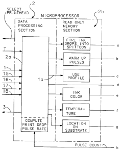
The organizational concept of that aspect of this
temperature control system is illustrated in Figure 2. In
Figure 2 the microprocessor 2 is shown in dot-dash outline.
For the purpose of this description, it comprises a data
processing section 2a and a read only memory section 2b. The
data processing section uses the print data instructions on
bus 1 to provide input by a bus la to a pulse generator 24a
in the logic array circuit 24 for printing text. Print pulse
timing in this respect is determined by the microprocessor
using the print drop firing signals on the bus 15 at an
input of the data processing section. Thus text is printed
by the printhead 21 as the print carriage sweeps in its axis
between the print limit bands B on the scale.
The output of the pulse generator 24 is coupled to
the printhead drive circuits 22 through a print pulse coun-
ter 24b forming part of the logic array circuit 24. The out-
put of the print pulse counter is coupled back to the data
processing section 2a of the microprocessor where it is used
to compute the print drop pulse rate of the printhead. This
print drop pulse rate is used by the data processor in
accessing use profiles in its read only memory section, for
providing pulse generating input to the pulse generator so
that, for example, in a multi-printhead printer another
printhead may be selected for printing. In the alternative,
for example, in a single printhead arrangement, excessive
temperature alone or rising temperature with a high use
profile may be processed by the data processing section of
--11--
1 3 r~ 5 f~
the microprocessor to produce a control to reduce data
throughput to prevent the rise in temperature. This
concept is tied in with the dwell time between the lines
of print data. It is feasible because the printhead
temperature time constant is long in comparison with the
carriage sweep time in the axis. Thus the
microprocessor produc~s motor control of a character to
provide a predetermined dwell time of the carriage in
either of the sweep limit bands A on the scale. These
dwell intervals may take place at the end of each
carriage sweep or at the end of selected carriage sweeps
to control the printhead temperature as required.
Where multiple nozzle arrays are provided on a
single substrate, the location of the nozzle array on
the substrate has a bearing on its temperature.
Similarly ink color is a factor in temperature control
because some colors are more sensitive to low
temperatures than others.
When the printhead is not in use, it resides
in a park or rest position in a limit of carriage
movement in which the carriage is removed entirely of
the carriage print sweep range. This position is
determined by a park band C on the scale, as seen in
Figure 1. When not in use, head temperatures may be
below those which are acceptable for printing. The
printhead assembly 21 is shown in park position in dot-
dash outline in Figure 1. Adjacent the printhead, in a
position toward the adjacent sweep limit band A on the
scale, is a spittoon 27, also shown in dot-dash outline.
In this circumstance, when a print demand is made, the
data processor section of the microprocessor may
1 3r`~956
determine that a viscous plug exists in the printhead
nozzle. Thus, when the command is issued for the
carriage to move out of park position to perform a
printing operation, the microprocessor provides an
instruction to the pulse generator 24a to produce print
drop firing pulses timed to expel print drops into the
spittoon as the carriage moves out of the park position
for a printing operation. This operation clears any
plugs which may exist in the nozzles and additionally
provides a degree of warm up depending upon the number
of print pulses that have been applied in firing ink
drops into the spittoon.
In other circumstances, if the printhead
exists in a low temperature situation unacceptable for
printing and the use profile is such that no viscous ink
plugs exist in the nozzle, warm up pulses for the
printhead may be selected. Warm up pulse instructions
from the microprocessor, initiated by the data
processing section accessing the warm up pulse data of
the read only memory section, provides instructions to
the pulse width control section of the pulse generator
24a to produce warm up pulses. These are time limited
voltage bursts which heat but are too short to expel ink
from the printhead.
The flow chart of Figure 3 characterizes these
functions of the temperature control system. If there
is overheating the decision is to stand idle as in dwell
time in the sweep limit bands A of the carriage, or in a
multi-nozzle single color head assembly, to shift
nozzles. In the event of a viscous plug, warming pulses
X
.. ... ..
1 3C~956
and/or spitting of the nozzles may be employed. In the
event the nozzles are cold, nozzle pulsing for warming
and/or spitting may be employed. These decisions and
actions always precede a following printing operation.
Industrial Applicability
This printhead temperature control for
maintaining uniformity and quality of print or graphics
is applicable in all thermal inkjet systems.
14
.
_v . ^