Note: Descriptions are shown in the official language in which they were submitted.
1 3','~,95~
IMPROVED LINER_CONFI~URATION
The present invention relates to an improved centrifugal
pump and in particular to an improved liner construction for
centrifugal slurry pumps and method of construction thereof and
particularly to centrifugal slurry pumps wherein because of
their method of construction a sharp discontinuity occurs on
the inner surface because of the mating of the liner components.
As these pumps are used in slurry applications, hard metal
or elastomeric liners are necessary to minimise wear. As the
metal and elastomeric liners are required to be
interchangeable, it is necessary to make the liners of
different materials with the same internal ~hydraulic~ shape,
so that performance does not change when liners are changed.
With hard metal liners, the only available method to
conform the liner to the required dimensions until recently was
by means of grinding. Grinding is slow and costly and is
confined to flat surfaces, readily accessible to large grinding
wheels. Therefore the grinding of excess materials from hard
metal liners was restricted to the minimum.
Hard metal parts made from a casting process are difficult
to control dimensionally, particularly when cores are used, as
cores can shift and cause variations in casting thickness. As
it is necessary that the liner and its parts must fit exactly
within required tole-rances in the casing as shown in Figure 3,
the outer surfaces 16 of the volute liner 1 and the outer
surace }5 and 17 respectively of the throat bush 2 and frame
plate liner insert 3 (as shown in Figure 1 and 2) are machined
to the re~uired width.
_ '
1 3r`1~`958
In Figure 2 is shown a close-up of the fitting of the
throat bush 2 and the volute liner 1 in the prior art pump shown in
section view in Figure 3. Because the parts are produced as
cast metal liners or as moulded elastomeric liners as is
required by the medium to be pumped, it is necessary that the
mating surfaces 6 and 7 of both the volute liner 1 and the
throat bush 2 are produced to smooth finish to ensure accurate
fitting of the mating parts. Further to fit the liners into
the pumps the outer surfaces 15 and 16 are machined. The inner
surfaces of the liner are not machined.
8ecause of the above considerations, it is extremely
difficult to cast two separate hard metal parts such as a
volute and throat bus~ which,when ground and fitted together,
have the inside surfaces matching exactly.
As it was not practical to make the liner parts' inner
surfaces flush, the side liners (i.e. throat bush 2 and frame
plate liner insert 3) were allowed to protrude further inwards
than the inside surface 8 of the volute liner 1 as shown in
Figures 1 to 4. This configuration is preferable from a wear
~0 point of view than having the inside liners thinner than the
volute liner as shown in Figure 5.
In order that elastomeric lined pumps have the same
performance as metal lined pumps, the elastomeric liners are
produced with the same internal shape as the metal liners,
although the rubber liners can be moulded to very much closer
tolerances than metal liners.
It is known that, when slurries or liquids having
entrained solids are pumped, the solids can cause wear on the
C
1 3r~9r~
parts of the pumps.
Eddying and unwanted turbulence are formed near areas of
the pump casing or liner which have abrupt discontinuity, such
as steps, of the surface profile.
This problem is particularly associated with the mating of
the throat bush and the volute liner, and the mating of frame
plate liner insert and the volute liner in pumps where
com~onents are metal (e.g., cast metal) and the res ~ tive mating surfaces require
machining or the like. As shown in Figures 1 to 4 there is a
discontinuity 4 in the form of a step 5 on the inner surface of
the liner between the volute liner 1 and the throat bush 2 and between
the volute liner 1 and the frame plate liner insert 3 in prior
art centrifugal slurry pumps.
This discontinuity causes eddying and turbulence around
the step 5 with consequential abrasion by the entrained solids
of the volute liner and side liners, producing a high wear
area, as shown in Figurè 6. The flow leaving the pump impeller
enters the internal pump passageway, but because of the step 5
on the side liners 2 and 3, eddies can cause a concentration of
wear at the step 5 and subsequent wear on the joint faces as
shown. Thus the volute liner fails prematurely and only in a
localised area near the joints between the side liners and the
volute liner.
Because of recent advances in manufacturing techniques,
machining of hard metals is now not confined to grinding. Hard
metals can be machined by using special tooling on standard
turning/boring machines.
The present invention seeks to ameliorate the above
disadvantages.
1 3~ 5~
In one broad form the invention comprises a method for
assembly of a liner for a centrifugal slurry pump comprising:
a volute liner having two opposed circular openings,
each opening having a first surface facing radially inwardly
thereto, an outer surface adjacent the first surface, facing
externally of the liner, and an inner surface adjacent the first
surface and facing inwardly of the liner;
a frame plate liner insert having a peripheral surface
and an inner surface and outer surface adjacent to and extending
radially from the peripheral surface; and
a throat bush liner having a peripheral surface, and
an inner surface and outer surface adjacent to and extending
radially from the peripheral surface.
The method comprises the steps of machining the outer
surfaces of the throat bush and the frame plate liners so as to
produce the required thickness between the outer surface and the
inner surface of each of the frame plate liner and the throat
bush liner;
machining the peripheral surfaces of the throat bush
and the frame plate liners to predetermined diameters;
machining the volute liner on the outer and inner
surfaces to produce a thickness therebetween, whereby in use the
inner surfaces of the throat bush and the frame plate liner is
such so as to correspond with the respective thickness between
the outer and inner surfaces of the throat bush and the frame
plate liners; and
machining the first surface of the volute liner, and
the peripheral surfaces of the throat bush liner and the frame
plate liner such that when the frame plate liner and the throat
bush liner are inserted into the respective openings of the
volute liner the respective surfaces thereof are aligned.
The present invention will now be described by way of
example with reference to the accompanying drawings, in which:
Figs. 1-6 illustrate fragmentary cross-sectional views
of prior art liners;
D
1 3 !, 3 ~ ")
Fig. 7 illustrates a detail of a cross-section of the
volute liner at its opening, which is made according to one
embodiment of the present invention:
Fig. 8 illustrates the mating of the above volute liner
with a throat bush with the components suitably ground to the
required sizes:
Fig. 9 illustrates a cross-sectional view of the mating of
the above volute liner with both side liners: and
- 4a -
'~`J
1 3"~9~Q,
Fig. 10 illustrates the area of the opening in an
elastomeric volute liner to receive the throat bush.
As mentioned previously, because the sealing faces and the
back faces of the volute liner, the throat bush and the frame
plate liner insert have to be machined to assure accurate fit
therebetween and accurate fit in the pump casing, it is
difficult to align the inner faces or surfaces 8 and 9, and
hence a discontinuity with its resultant step 5 occurs (see
Fig.2).
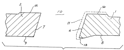
As shown in Figure 7, according to the present invention the
area of the opening 10 of the volute liner is cast with a thickened
protrusion 11 (as shown by dotted lines).
The mating faces or surfaces 6 and 7 and the back faces 15
and 16 of the volute liner and throat bush are machined to the
required degree such that t~e parts fit together in sealing
relationship. This leaves a small projection 13 on the inner
surface of the volute liner 1.
This is then removed when the final fitting of the throat
bush to the liner has occurred to form a smooth transition 14
from the inner surface 9 of throat bush 2 to the inner surface
8 of the volute liner 1, as shown in Figure 8~ without weakening
the liner due to reduction in thickness. A similar procedure is
carried out with frame plate liner insert opening to produce an
alignment as shown in Figure 9.
A similar shaped thickening 15 is used with elastomeric
volute liners 11 as shown in Figure 10.
However, as elastomeric material can be moulded more
accurately than hard metal, no machining is necessary. Thus
~ 3"'`'`95~
the volute liner has been thickened adjacent its joint with the
side liners producing a smooth alignment of the volute liner
and side liners inner surfaces.
It should be obvious to pe-ople skilled in the art that
variation and modifications can be made to the above without
departing from the scope or the spirit of the present invention.
-- 6 --