Note: Descriptions are shown in the official language in which they were submitted.
~3~913~ 20365-2857
CURRENT CONNECTION DEVICE
This invention relates to a current connection device
for coupling elect~ochemical cells together in a battery. More
particularly, the device is for use in fuel cells and has metallic
contact elemen-ts in the form of metallic contact sheets which form
pressure cushions.
Back rounds of the Invention
A battery which uses metallic contact bodies which form
pressure cushions is disclosed in U.S. Patent No. 4 317 864. The
contact bodie~ ~ulfil.l two functions: they collect the current
from each cell and they have a hollow chamber into which a
pressurized medium may be introduced so that uniform compression
is exerted on the catalyst material in the adjacent cells.
The electrochemical cells in such a battery are stacked
one upon another in a bipolar array, with one pressure plate loca-
ted at either end of the stack. Between the pressure plate and
the pressure cushion of the first electrochemical cell a metal
plate with an outward projecting strip is located. This plate is
called the pole plate and serves as the current collection and
battery connection point.
Electrical contact between the pole plate and the con-
tact bodies (pressure cushions) is established by pressurizing the
hollow chamber in the contact bodies. Either a pressurized gas or
liquid can be used. However, reliable electrical contact con-
tinues only so long as the battery is operated in an atmosphere
whose pressure is below that maintained in the contact bodies. If
;~
: : :
`
~9~3~ 20365-2857
ambient pressure exceeds the pressure in the contact bodies, the
current ls either interrupted or the contact body, because of the
loss of contact area, overloads thermally. Thus, the functional
reliability o-E the battery is endangered.
One attempt to solve the foregoing problems consisted of
gluing the pole plates into a plastic plate. The pole plate was
then sealed in an elastomer frame and replaced in the battery.
The space between the pole plate and the pressure cushion was
thereby sealed off from the ambient pressure and changes in the
ambient pressure no longer affected the contact.
~ hat solution, however, had several disadvantages.
First, gluing the pole plate into a plastic plate involved prob-
lems relating to the different coefficients of heat expansion in
the materials and the dimensional changes attendant thereto.
Mechanical tension caused by the gluing process and thermal
stresses occurring during use generated tears and, finally,
pressure leakage between the outside environment and the contact
area, which impaired battery operation. Second, in order to
insure the battery's ~unctioning despite the small lea~s, the
space between the pole plate and the pressure cushion needed to be
vented to ambient atmosphere. To maintain a relatively constant
pressure within this space required costly monitoring and pressur-
izing equipment. Third, as multiple cells exist in each stack,
the construction method was relatively costly.
Summary of the Invention
It is an object of this invention to create a current
2 --
~,
. t `~
' ' ' , : .
~3~3~ 20365-2857
connection device for batteries using electrochemical cells, the
device having contac-t bodies functioning as pressure cushions for
generating isostatic contact pressure and which contact bodies
permit the connection of cell groups in parallel.
- 2a -
" ~3~31
20365-28~7
According to a broad aspect o~ the inventlon there ls
provided a curren~ connection device for use in electrochemical
battery cells, particularly ~uel cells, comp.rising metal plate
means;
contact sheet means welded to both sides of the plate means
for providing pressure cushions to the cells;
elastomer frame means surrounding the plate means and contact
sheet means, completely sealing all edges on both sides of the
plate means; and
metal strip means attached to the plate means projecting
through the frame means to outside the battery cell for providing
a current connection point.
In this manner the pole plate is integrated into the
pressurç cushlon. The parts and structure are easy to fabricate
and overcome the limltations of the prior art.
In a particulary advantageous embodiment, the plate and
strip are composed O:e copper and the contact sheets are stamped in
a wave-like pattern.
Other and further ob~ects of this invention will become
obvious upon an understanding of the illustrative embodiments
about to be described with reference to ~he figure or will be
indicated in the appended claims, and further advantages not
referred to herein will occur to one skilled in the art upon
employment of the invention in practice.
Descrip~ion of the F~ure
The Figure shows a cross-section o~ a battery cell
; ~ . . . .
' , . ~
'
~3~9~31
20365-2857
Gontaining the present invention.
Detailed Descri~ion of ~he Inven~ion
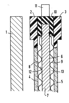
Referring to the Figure, a cross-section of a portion of
a battery containing the present invention is shown. Pressure
plate 1 is located at the end of the battery. Located be~ween it
and its mirror image at the other end of the battery (not shown)
are a plurality of battery cells, each cell comprised of cell
frames 2 and 3~ electrodes 4 and 5, and current connection device
6. In the cells located ad~acent to
3a
13~9~3~ 1
1 ` pressure plates at the respective ends of the battery, cell
2 frame 2 and electrode 4 or cell frame 3 and electrode 5 are
3 omitted as required to maintain corect polarity.
4 Current connection device 6 is comprised of metal
Iplate 7, two contact sheets 8 and 9 and elastomer frame 10
6 which surrounds the edges of plate 7. Contact sheets 8 and 9
7 are welded to metal plate 7. Metal plate 7 has a metallic
8 'strip 11 which extends through frame 10 to outside the cell.
g ~Strip 11 is used for external current connection and preferably
,~extends radially from the cell. Chambers 12 and 13 between
metal plate 7 and contact sheets 8 and 9 hold fluid which is
12 ¦used to generate pressure in the cells.
13 Pressure plate 1 is comprised of plastic or metal
14 ~ covered with plastic. Metal plate 7, together with strip 11,
1 is also known as the pole plate, is comprised of copper
16 l approximately 1 mm thick, and i9 Icemplctclylcovered by welded-
17 , on contact sheets 8 and 9. Sheets 8 and 9 are only
18 1 approximately 0.2 mm thick and flexib].e and can be comprised
19 1 of nickel. The sheets are stamped in a wave pattern, with wave
heights of approximately 1 mm, thereby forming gas guide paths
21 for the gaseous reactants of the battery. These reactants may
22 be hydrogen and/or oxygen and are supplied to electrodes 4 or 5
23 under a pressure of about 2 bar. The battery's electrolyte can
24 be potassium hydroxide. The pressure medium supplied to
chambers 12 and 13 may be ~ nitrogen supplied at a
26 ~ pressure of about 3 bar.
27 ~l As many apparently widely different embodiments of
28 1¦ this invention may be made without departing from the spirit
29 ,¦and scope thereof, it is to be understood that the invention is
,lnot limited to the specific embodiment~ thereof except as
.!
1! -4-
. . '
~3C~33L
defined in the appended claims.
.
~,1
5 :
.. - -