Note: Descriptions are shown in the official language in which they were submitted.
13~r~,7,~
BACKGROUND OF THE INVENTION
Field of the Invention
This invention relates to the dispensing of liquids and more
particularly, this invention relates to an improved applicator
device for marking, writing or dispersing a liquid on a surface.
Description of the Prior Art
Various types of devices have been devised for marking or
writing with ink, dye or paint. Among such devices are fountain
pens, ball point pens, felt tip pens, capillary tube pens, fiber
tip pens and the like. In addition, various other applicator
devices have been devised in the prior art for applying and/or
the dispersing a wide variety of other viscous and non-viscous
liquid products such as perfumes, glues, insect repellants, oils,
greases, lubricants and the like. The writing, marking and
applicator devices of the prior art have received wide acceptance
due in great measure to the convenience of the device and the
ability to retain a large quantity of liquid in a liquid container.
Further, the writing and applicator devices of the prior art have
received wide acceptance due to the ability to supply additional
applicator liquid from a liquid container to a surface applicator at
the discretion of the user.
Continuing efforts have been made in the past to improve
the design of applicator devices, particularly in the mechanism for
improving the communication of the applicator liquid from the
liquid container to the surface applicator for writing, marking or
otherwise applying the applicator liquid on a surface. In a typi-
cal prior art applicator device, the applicator liquid flows to the
surface applicator only when the applicator device is held upside
down allowing the applicator liquid to flow to the surface applica-
tor by action of gravity.
Prior to the advent of the present invention, there have
been various problems in the design, fabrication, assembly and
the utilization of applicator devices of the prior art. Most prior
art devices incorporating a valve have required an excessively
-- 2 --
large number of parts. In general, the prior art applicator
devices incorporating a valve had to be filled with the applicator
liquid and then held in an upright orientation during the process
of assembling the remainder of the applicator device. Accord-
ingly, the completed but unassembled component parts of the
liquid applicator device had to be shipped from a component parts
manufacturer to a filling plant whereat the component parts had
to be assembled concurrently with the filling of the containers.
In general, the filling plants desire to undertake only the final
assembly of a product as opposed to undertaking the entire
assembly as required by the prior art applicator devices. This
necessarily increased not only the total manufacturing cost, but
also required the filling plant to provide an additional assembly
line as well as to provide the quality control for the applicator
device mechanism.
Accordingly, writing, marking and applicator devices of the
prior art did not permit the assembly of the applicator mechanism
independent of the final assembly at a filling plant. As a result
of these and various other factors, the unit price for liquid
applicator devices has been unnecessarily high.
It should be readily appreciated that the fabrication of the
valve mechanism of an applicator device independent of the liquid
container is a significant advancement in the art. The applicator
device of the present invention allows for the fabrication and
assembly of the applicator device mechanism from a single manu-
facturing site. Thereafter, the applicator device mechanism may
be shipped to a filling plant whereat the liquid container may be
filled with an applicator liquid. The applicator device mechanism
may then be sealed to the filled liquid container. Furthermore,
the improved applicator device of the present invention permits a
user to separate the applicator device mechanism from a depleted
liquid container without disassembling the applicator device mech-
anism. Consequently, the applicator device of the present inven-
tion could be refilled by the user to thereby extend the utility of
applicator device and to further reduce the overall cost of the
use of the applicator device.
13(:'23~Z
-- 3 --
_, . ~
. ~
In the present patent application, we
have again improved upon the novel valve assembly through the
incorporation of a superior sealing member interposed between the
valve and the surface applicator which totally eliminates the need
for a foam ring or foam disk sealer as required by most of the
prior art devices . In addition, the novel sealin g member of the
present invention provides liquid seal between the valve and the
surface applicator heretofore unknown in the art.
Therefore, it is an object of the present invention is to pro-
vide an improved applicator device for dispensing an applicator
liquid wherein the applicator device mechanism may be constructed
independently of the liquid container and subsequently coupled to
the filled liquid container to form the completed applicator device.
Another object of the present invention is to provide an
improved applicator device for dispensing an applicator liquid
having an increased ease of assembly herein unknown in the prior
art .
Another object of the present invention is to provide an
improved applicator device for dispensing an applicator liquid
which is more economical than the prior art applicator devices
through the incorporation of component parts which permit the
applicator device mechanism to be assembled by an assembly
machine independent of the liquid container.
Another object of the present invention is to provide an
improved applicator device for dispensing an applicator liquid
which permits a user to separate the applicator device mechanism
from a depleted liquid container without disassembling the appli-
cator device mechanism for enabling the applicator device to be
refilled by the user.
h
13~ 2
Another object of the present invention is to provide an
improved applicator device for dispensing liquids such as inks,
dyes, paints or chemicals and dispensing a wide variety of other
types of viscous and non-viscous liquid products such as glues,
insect repellants, oils, greases, lubricants, coating and the like.
Another object of the present invention is to provide an
improved applicator devicc for dispensing an applicator liquid
incorporating a surface applicator which permits a user to dis-
perse the dispensed liquid on the surface.
Another object of the present invention is to provide an
improved applicator device for dispensing an applicator liquid
incorporating a valve for sealing the liquid container of the appli-
cator device to prevent evaporation of the liquid in the liquid
container .
Another object of the present invention is to provide an
improved applicator device for dispensing an applicator liquid
incorporating a valve that is moveable into an open position upon
a user depressing a substantially rigid surface applicator on a
surface .
Another object of the present invention is to provide an
improved applicator device for dispensing an applicator liquid
incorporating a valve that is moveable into an open position upon
a user depressing a valve actuator for applying the liquid on a
surface by a flexible surface applicator.
Another object of the present invention is to provide an
improved liquid applicator device for dispensing an applicator
liquid which provides an improved support for a surface applica-
tor in the form of a fiber tip.
Another object of the present invention is to provide an
improved liquid applicator device for dispensing an applicator
liquid for use with a surface applicator in the form of a flexible
applicator such as a paint brush or the like.
Another object of the present invention is to provide an
improved applicator device for dispensing an applicator liquid
incorporating a liquid container, a valve closure, a valve body, a
valve element and bias means for sealing the liquid container and
131~9;~1~32
5 --
for dispensing and dispersing the liquid on the surface upon
movement of the valve element into an open position.
Another object of the present invention is to provide an
improved applicator device for dispensing an applicator liquid
which is convenient for painting, marking, or applying a liquid to
a surface.
Another object Or the present invention is to provide an
improved applicator device for dispensing an applicator liquid
incorporating a novel sealing member having a superior seal
between the valve and the surface applicator.
Another object of the present invention is to provide an
improved applicator device for dispensing an applicator liquid
incorporating a novel sealing member which is yieldable for main-
taining a seal between the valve and a surface applicator
irrespective of lateral movement or bending of the surface
applicator relative to the valve.
Another object of the present invention is to provide an
improved applicator device for dispensing an applicator liquid
incorporating a novel sealing member which is suitable for use
with a liquid dispensing device having either a fiber tip surface
applicator or a brush surface applicator.
The foregoing has outlined some of the more pertinent
objects and advantages of the present invention. These objects
and advantages should be construed to be merely illustrative of
some of the more pertinent features and applications of the
intended invention. Many other beneficial results can be obtained
by applying the disclosed invention in a different manner or mod-
ifying the invention within the spirit and scope of the disclosure.
Accordingly, other objects and advantages and a fuller under-
standing of the invention may be had by referring to the
Summary of the Invention and the Detailed Description describing
the preferred embodiments in addition to the scope of the
invention defined by the Claims taken in conjunction with the
accompanying Drawings.
13(~'.'3~t~2
-- 6 --
SUI~5MARY OF THE INVENTION
The present invention is defined by the appended claims
with the specific embodiments shown in the attached drawings.
For the purpose of summari~ing the invention, the invention may
be incorporated into apparatus comprising a liquid applicator
device for applying an applicator liquid from a liquid container to
an applicator surface. In one embodiment of the present inven-
tion, the liquid applicator device includes an inner subassembly
and an outer subassembly. The inner subassembly includes a
valve being movable between an open position and a closed posi-
tion for permitting and inhibiting the flow of the applicator liquid
from the liquid container. The outer subassembly receives a sur-
face applicator with a distal end of the surface applicator being
exposed for applying the applicator liquid to the surface. A
proximal end of the surface applicator communicates with the
valve of the inner subassembly when the inner subassembly is
secured to the outer subassembly. Axial depression of the distal
end of the surface applicator causes displacement of the valve
from the closed position to the open position to permit the flow of
the applicator liquid from the liquid container to the proximal end
of the surface applicator to enable the applicator liquid to flow to
the distal end of the surface applicator.
In another embodiment of the invention, the liquid applicator
device includes a valve having a valve element with the valve
element being movable between an open position and a closed
position. A valve closure has a first and a second end with an
internal closure cavity extending therebetween. The valve
closure receives a surface applicator having a proximal end and a
distal end with the surface applicator being disposed in the
internal closure cavity of the valve closure. The valve closure is
connected to the valve with the proximal end of the surface
applicator being disposed proximate the valve element and with
the distal end of the surface applicator extending external the
second end of the valve closure. The first end of the valve
closure is connected to the liquid container for enabling the flow
13l~3~2
-- 7 --
of the liquid from the liquid container to the surface applicator
when the valve element is disposed in an open position. A seal
means is provided for forming a liquid seal between the proximal
end and the dista] end of the surface applicator for directing the
flow of the applicator liquid from the liquid container to the
proximal end of the surface applicator.
In one specific ernbodiment of the invention, the seal means
comprises a tubular portion slidably receiving the surface appli-
cator for forming a liquid seal between the proximal end and the
distal end of the surface applicator. In another embodiment of
the invention, the seal means comprises a tubular portion slidably
receiving the surface applicator which is flexibly mounted within
the internal closure cavity of the valve closure to maintain the
liquid seal between the tubular portion and the surface applicator
irrespective of any deformation of the surface applicator.
In a more particular embodiment of the invention, the sur-
face applicator is substantially cylindrical for cooperation with a
cylindrical inner orifice of the tubular portion for slidably
receiving the substantially cylindrical surface applicator. The
means for flexibly mounting the tubular portion within the inter-
nal closure cavity of the valve closure preferably includes a resil-
ient plastic extending portion secured to the valve seal. In one
example of the invention, the resilient plastic extending portion is
secured to the valve seal and the extending portion is secured to
a generally central area of the tubular portion. Preferably, the
resilient plastic extending portion is integrally formed with the
valve seal and the tubular portion.
The applicator device may be used with a surface applicator
which is substantially rigid such as a fiber tip or a flexible sur-
face applicator such as a brush. In the case of a flexible surface
applicator, a rigid valve actuator cooperates with the flexible
applicator for moving the valve element from the sealing position
to the open position upon depression of the valve actuator on a
surface .
In another embodiment of the invention, the liquid applicator
device comprises an inner subassembly and an outer subassembly.
13Gg3~2
- 8 -
The inner subassembly includes a valve body, a valve element, a
valve seal and bias means. The valve element is movab]e between
an open position and a closed position. The outer subassembly
inc]udes a valve closure and a substantially cylindrical surface
applicator. The valve closure has a first and a second end with
an internal closure cavity extending therebetween. The surface
applicator ha~c a proximal end and a distal end with the surface
applicator being disposed in the internal closure cavity of the
valve closure. The outer subassembly includes a tubular portion
flexibly mounted to the valve closure for slidably receiving the
surface applicator for forming a liquid seal between the proximal
end and the distal end of the surface applicator and for main-
taining the liquid seal irrespective of any deformation of the sur-
face applicator. The inner subassembly is connected to the outer
subassembly with the proximal end of the surface applicator being
disposed proximate the valve element and with the distal end of
the surface applicator extending external the second end of the
valve closure. The first end of the valve closure is secured to
the liquid container for enabling the flow of the liquid from the
liquid container to the surface applicator when the valve element
is disposed in the open position.
The foregoing has outlined rather broadly the more pertinent
and important features of the present invention in order that the
detailed description of the invention that follows may be better
understood so that the present contribution to the art can be
more fully appreciated. Additional features of the invention will
be described hereinafter which form the subject of the claims of
the invention. It should be appreciated by those skilled in the
art that the conception and the specific embodiments disclosed
may be readily utilized as a basis for modifying or designing
other structures for carrying out the same purposes of the
present invention. It should also be realized by those skilled in
the art that such equivalent constructions do not depart from the
spirit and scope of the invention as set forth in the appended
claims .
~3~ 2
_ 9 _
BRIEF DESCRIPTION OF THE DRAWINGS
For a fuller understanding of the nature, objects and advan-
tages of the invention, reference should be made to the following
detailed description taken in connection with the accompanying
drawings in which:
Fig. 1 is a side elevational view of a first embodiment of a
liquid applicator device of the present invention;
Fig. 2 is an exploded viçw illustrating the first embodiment
of the liquid applicator device of Fig. l;
Fig. 3 is an enlarged sectional view of the liquid dispensing
mechanism of Fig. 1 shown in a closed position;
Fig. 4 is an enlarged sectional view of the liquid dispensing
mechanism of Fig. 1 shown in an open position;
Fig. 5 is a partial enlarged sectional view along line 5-5 in
Fig. 3 showing only a valve body;
Fig. 6 is a partial enlarged sectional view along line 6-6 in
Fig. 4 showing only a valve body;
Fig. 7 is a partial enlarged sectional view along line 7-7 in
Fig. 4 showing only a valve element;
Fig. 8 is an enlarged sectional view of second embodiment of
the ]iquid dispensing mechanism shown in a closed position;
Fig. 9 is an enlarged sectional view of the second embodi-
ment of the liquid dispensing mechanism shown in an open posi-
tion;
Fig. 10 illustrates the first step in a method of forming the
liquid dispensing mechanisms of the present invention;
Fig. 11 illustrates the second step in the method of forming
the liquid dispensing mechanisms of the present invention;
Fig. 12 is a side elevational view of a third embodiment of a
liquid applicator device of the present invention;
Fig. 13 is an exploded view illustrating the third embodiment
of the liquid applicator device of Fig. 12;
Fig. 14 is an enlarged sectional view of the liquid dispensing
mechanism of Fig. 12 shown in a closed position;
13~g3~2
- 10 --
Fig. 15 is an enlarged sectional view of the liquid dispensing
mechanism of Fig. 12 shown in an open position;
Fig. 16 is an enlarged sectional view of a fourth embodiment
of the liquid dispensing mechanism shown in a closed position;
Fig. 17 is an enlarged sectional view of the fourth embodi-
ment of the liquid dispensing mechanism shown in an open posi-
tisn;
Fig. 18 is a view alon~ line 18-18 in Fig. 17;
Fig. 19 illustrates the movement of a valve actuator shown in
Figs. 16-18 by the finger of a user;
Fig. 20 is an elevational view of a fifth embodiment of the
present invention illustrating the dispensing mechanism in
combination with a flexible wall container;
Fig. 21 is a side elevational view partially in section of a
sixth embodiment of the present invention illustrating an applica-
tor device having plural surface applicators for dispensing a
single applicator liquid;
Fig. 22 is a side elevational view partially in section of a
seventh embodiment of the present invention illustrating an appli-
cator device having plural surface applicators for dispensing
plural applicator liquids;
Fig. 23 is a side sectional view of an eighth embodiment of
the liquid dispensing mechanism shown in a closed position and
incorporating an improved seal for the surface applicator;
Fig. 24 is a side sectional view of the eighth embodiment of
the liquid dispensing mechanism of Fig. 23 shown in an open
position;
Fig. 25 is a side sectional view of the eighth embodiment of
the liquid dispensing mechanism of Figs. 23 and 24 showing a
deformation of the surface applicator upon the surface applicator
contacting a surface;
Fig. 26 is an enlarged partial side sectional view of the seal
shown in Figs. 8 and 9;
Fig. 27 is an enlarged partial side sectional view of the seal
shown in Figs. 23-25;
131~
Fig. 28 is an enlarged partial side sectional view of a modifi-
cation of the seal shown in Figs. 8 and 9; and
Fig. 29 is an enlarged partial side sectional view of a modifi-
cation of the seals shown in Figs. 26-28.
Similar reference numerals refer to similar parts throughout
the several views of the drawings.
130`~?38Z
- 12 -
DETAILED DISCUSSION
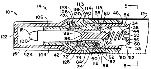
Fig. 1 is an elevational view of a first embodiment of the
present invention illustrating a liquid applicator device 10 com-
prising a liquid container 12, an applicator mechanism 14 and an
overcap 16. The applicator mechanism 14 includes a surface appli-
cator 18 shown as a fiber tip for applying an applicator liquid to
a surface (not shown) upon the depression of the fiber tip 18
against the surface.
Fig. 2 is an exploded view of a first embodiment of the
present invention shown in Fig. 1. The liquid container 12 is
preferably constructed of a non-permeable metallic or plastic sub-
stance and is provided with a closed end 22, an open end 24 and
cylindrical side walls 26. The open end 24 is adapted to receive
and store a quantity of applicator liquid. When the applicator
device 10 is used to apply a marking liquid, the marking liquid
may be formed of opaque particles suspended in a carrier liquid.
The applicator device 10 may include agitator means 28 shown as
a single ball but a plurality of balls or a metal slug may be dis-
posed within the liquid container 12. Preferably, the agitator
means 28 is formed of a metallic substance having a specific grav-
ity significantly greater than the carrier liquid and with the
metallic material being selected to minimize any chemical reaction
with the carrier liquid. The agitator means 28 disburses the sus-
pended opaque particles within the carrier liquid in the event
that the suspended opaque particles have become precipitated or
settled from the carrier liquid.
The dispensing mechanism 14 includes an inner subassembly
31 and an outer subassembly 32 as also shown in Figs. 2-4. The
inner subassembly 31 includes a valve body 34, bias means shown
as a spring 36, a valve element 38 and a valve seal 40. The
outer subassembly 32 comprises a valve closure 42, the surface
applicator or fiber tip 18 and a foam collar 43. The valve body
34, the valve element 38, the valve seal 40 and the valve closure
42 are preferably formed of a plastic material or complementary
plastic materials. The bias means is shown in this embodiment as
13(~
- 13 -
a compression coil spring 36 which is preferably formed of stain-
less steel or another suitable material to preclude or minimize
chemical reaction with the applicator liquid. Although the bias
means has been shown as a compression coil spring 36 in the
drawings, it should be understood that various other bias means
may be used such as an integral plastic spring as disclosed in
United States Patent 4,471,893.
As shown in greater detail in Figs. 3 ~ 4, 5 and 6, the valve
body 34 is a cup-shaped configuration having a bottom face 44,
cylindrical side walls 46 and an enlarged annular open top having
a shoulder 48. The bottom face 44 of the valve body 34 is of a
generally triangular shape defining voids 49 between the apices
49A of the triangle as shown in Fig. 5. In order to allow essen-
tially unrestricted flow of the applicator liquid from the liquid
container 12 into the valve body 34, the valve body 34 is pro-
vided with aperture means shown in this embodiment as a plu-
rality of liquid passing apertures including an axial hole 50 and a
plurality of slots 52. The hole 50 is disposed in the bottom face
44 whereas the plurality of slots 52 are formed transversely in
the peripheral sidewalls 46 of the valve body 34. The slots 5Z
are located adjacent the voids 49 to form large flow openings 53
between the inside surface of the liquid container 12 and the
valve body 34 to facilitate the flow of the applicator liquid there-
between. A plurality of spring orientating ribs 54 are formed in
the valve body 34 and extend between an inside surface of the
cylindrical sidewalls 46 and an inside surface of the bottom face
44 as shown in Fig. 3, 4, and 6. The orientation ribs 54 enable
the positioning of the coil spring 36 on a projection 56 extending
from the bottom face 44 of the valve body 34. The projection 56
surrounds the axial hole 50 and frictionally engages the inner
diameter of an inner spring end 60 of the coil spring 36. The
inner diameter of an outer spring end 62 of the coil spring 36 is
adapted to frictionally engage a projection 64 extending from the
valve element 38.
The valve element 38 is formed in a cup-like configuration,
with a closed face 72 and with circumferential side walls 74 and
~3~93l~2
an open end 76. As also shown in Fig. 7, strengthening ribs 78
are located within the valve element 38 and extend from an inner
surface of the closed face 72 to the open end 76 and terminate in
the projection 64 which matingly engages the inner diameter of
the outer end 62 of the coil spring 36. A sealing surface 80 is
formed on a flared peripheral shoulder located on an open end 76
of the valve element 38. A flexible sealing seat 82 is formed on
the inner end of the valve seal 40. The diameter of the sealing
surface 80 is greater than the diameter of the sealing seat 82.
Spring 36 urges the reciprocal valve element 38 into a closed
position as shown in Fig. 3 whereat the sealing surface 80 of the
valve element 38 is in contact with sealing seat 82 of the valve
seal 40 to inhibit the the flow of applicator liquid therethrough.
The valve element 38 may be moved to an open position as shown
in Fig. 4 whereat the sealing surface 80 of the valve element 38
is displaced from the sealing seat 82 of the valve seal 40 to per-
mit the the flow of applicator liquid therethrough. In this
embodiment, the depression of fiber tip 18 will compress the
spring 36 and displace the sealing surface 80 from the sealing
seat 82 as shown in Fig. 4. The sealing surface 80 is made
flexible by virtue of the thickness of the material and by virtue
of the selection of the valve seat material. The valve element 38
has a point 86 for receiving and positioning an inner end of the
surface applicator 18.
The valve seal 40 is generally cylindrically shaped and is
provided with a circumferential shoulder 84 of a diameter greater
than the remainder of the valve seal 40. The valve seal 40 is
inserted into the valve body 34 with the valve element 38 and
spring 36 located therebetween. The shoulder 84 of the valve
seal 40 engages with the shoulder 48 of the valve body 34 to limit
the depth of penetration of the valve seal 40 into the valve body
34. The shoulder 84 is substantially the same diameter as the di-
ameter of the annular shoulder 48 of the valve body 34 enabling
the first subassembly 31 to be inserted into the second sub-
assembly 32. annular projection 88 extends from the valve seal 40
whereas an annular recess 90 is disposed in the valve body 34.
The annular projection 88 is received within the annular recess 90
in an interlocking engagement to couple the valve seal 40 to the
valve body 34 to form the independent inner subassembly 31 of
the dispenser mechanism. The valve seal 40 is preferably a plas-
tic material such as polyethylene or other similar moldable material
which will assume a rigid shape but be slightly more flexible than
the polypropylene of the valve body 34 and valve element 38 to
allow the inner and outer subassemblies 31 and 32 to be readily
snapped together.
The outer subassembly 32 may be fabricated independently of
the inner assembly 31 and the liquid container 12. The outer
subassembly 32 of the first embodiment includes the surface appli-
cator 18 shown as a substantially rigid fiber tip, the valve clo-
sure 42 and a foam disk shown in this embodiment as a cylindrical
foam collar 43. The fiber tip 18 is a cylindrically shaped member
formed of a highly compacted fibrous material such as polyester
or other similar material having properties which enable the fiber
tip 18 to hold the original shape when moistened with the appli-
cator liquid while simultaneously being capable of passing the
applicator liquid from a proximal or an inner end 98 to a distal or
an outer end 100 of the fiber tip 18 by capillary action.
The valve closure 42 is a hollow element with an outer por-
tion 104 having tip centering ribs 106 on the inner surface
adapted to be frictionally engaged by the surface applicator 18 to
position and support the surface applicator 18. A central cylin-
drical portion 108 of the valve closure 42 is adapted to receive
the foam collar 43. The foam collar 43 is formed as a hollow
cylinder with an inner circumferential surface adapted to friction-
ally receive the surface applicator 18 therein. The exterior sur-
face of the foam collar 43 is adapted to be frictionally received by
the inner surface of the central portion 108 of the valve closure
42. In the alternative, a cylindrical disk may be disposed within
the central portion 108 for contacting the inner end 98 of the
surface applicator 18. In the case when a foam disk is used in
place of the foam collar 43, the inner end 98 of the surface appli-
cator 18 engages the foam disk. The surface applicator 18, valve
13~'~3~
- 16 -
closure 42 and the foam collar 43 comprise the independent outer
subassembly 32.
The val~e closure 42 has an inner portion 110 having a
diameter greater than the remainder of the valve closure 42 which
is provided with a circumferential inner recess 112 capable of
receiving and positively retaining an annular projection 114
extending from the valve body 34 of the inner subassembly 31.
In the assembled configuration the shoulder 84 of the valve seal
40 engages with shoulder 113 of the valve closure 42. Accor-
dingly, the inner and outer subassemblies 31 and 32 may be
joined together into a snap locking engagement by an automatic
machine process.
The applicator dispensing mechanism 14 is joined to the con-
tainer 12 in this embodiment by a press fit engagement. The
exterior diameter 115 of the valve closure 42 is tapered to be
inserted into the open end 24 of the container 12. The exterior
surface of the valve closure 42 is also provided with a shoulder
116 for engaging with the open end 24 of the container 12 to
axially limit the movement of the dispensing mechanism 14 relative
to the container 12.
The overcap 16 includes an inner end 120 having an internal
diameter selected for a friction fit with the valve closure 42. The
shoulder 116 of the valve closure 42 limits the movement of the
overcap 16 on the valve closure 42. The overcap 16 has a closed
outer end 122 positioned to avoid contact with the surface appli-
cator 18 when the overcap 16 is positioned on the valve closure
42 as shown in Fig. 3. The overcap 16 may be provided with
external gripping ribs 124 for aiding in the removal of the
overcap 16 by a user. The valve closure 42 and the overcap 16
are preferably formed of acetal or a similar moldable material
which will inhibit evaporation of any carrier liquid or solvent
within the applicator material.
Preferably, the valve closure 42 and the overcap 16 are more
rigid than the other elements of the applicator dispensing mecha-
nism 14. The foam disk or collar 43 is preferably formed of an
open cell, foaminous material to provide controlled flow of
13~93~3Z
-- 17 --
applicator liquid therethrough. The foam disk or collar 43 also
functions as a reservoir to provide applicator liquid to a larger
surface area of the surface applicator 18. The foam collar 43
further e]iminates the need for keeping the valve mechanism con-
tinuously open during the dispensing process. The foam disk or
collar 43, like all of the other elements of the liquid applicator
device 10 is fabricated from a material which will not be adversely
affected chemically when contacted by the applicator liquid.
As can be seen in E~igs. 3 and 4 the foam disk or collar 43
is located in a liquid chamber 128 defined by the valve element
38, the valve closure 42 and surface applicator 18 whereby
depression of the rigid fiber tip 18 will compress the spring 36 to
separate the sealing surface 80 of the valve element 38 from the
sealing seat 82 of the valve seal 40 as shown in Fig. 4. The
separation of the sealing surface 80 of the valve element 38 from
the sealing seat 82 of the valve seal 40 permits the flow of the
applicator liquid by action of gravity from the container 12
through valve body 34 to the liquid chamber 128 and then to the
surface applicator 18. The release of the depressing pressure
from the rigid fiber tip 18 will return the sealing surface 80 of
the valve element 38 into sealing engagement with the sealing seat
82 of the valve seal 40 as shown in Fig. 3 to inhibit the flow of
the applicator liquid from the container 12 to the rigid fiber tip
18.
Figs. 8 and 9 illustrate a second embodiment of the invention
shown in Figs. 2-7. In this second embodiment, the liquid dis-
pensing mechanism lOA is identical to the mechanism heretofore
described with similar parts being labeled with similar reference
numerals followed by the letter A. In this embodiment the valve
seal 40A includes an extending portion 150A having an inwardly
projecting wall 152A for contacting the surface applicator 18A.
The extending portion 150A and the inwardly projecting wall 152A
create a chamber 128A which functions as a liquid reservoir for
the inner end 98A of the rigid fiber tip 18A to replace the reser-
voir created by the foam collar 43 in Figs. Z-4. The inwardly
projecting wall 152A acts as a seal for the liquid chamber 128A
13(~
-- 18 --
and prevents the flow of the applicator liquid along the side of
the surface applicator 18A. The projecting wall 152A further
stabilizes the felt tip 18A. This contribution to the art not only
reduces the number of required parts and cost, but also facili-
tates the manufacturing process since the foam disk or collar 43
has been the most difficult element to handle in the assembly of
the liquid applicator device 10. In the manufacture of the prior
art liquid applicator devices, the sponge-like characteristics of
the foam collar 43 often required that the foam collars had to be
applied and assembled in a hand operation. The elimination of
the foam collar 43 from the liquid applicator device 10 and the
associated manufacturing process thus permits the entire fabrica-
tion and assembly process to be readily done on totally automated
machinery. The embodiment shown in Figs. 8 and 9 provide sup-
erior performance and eliminate the need for any foam which was
required in many of the prior art devices.
Figs. 10 and 11 illustrate in greater detail the method of
assembling the liquid applicator devices of the present invention
as described heretofore and described hereinafter. Fig. 10 shows
the coil spring 36 being frictionally attached to the cup-shaped
body 34 with the inner diameter of the inner spring end 60 being
received on the projection 56 of the inner surface of the bottom
face 44 of the valve body 34. The projection 64 extending from
the valve element 38 is then axially placed into a frictional rela-
tionship with the inner diameter of the outer spring end 62 of the
spring 36. The valve seal 40 is then axially press fit against the
shoulder 48 of the valve body 34 with recess 90 of the valve body
34 receiving projection 88 of the valve seal 40 as best shown in
Figs. 3 and 4. As also shown in Fig. 10, the cylindrical foam
co;lar 43 is frictionally located over the surface applicator 18 and
the outer end 100 of the surface applicator 18 is inserted into the
internal centering ribs 106 of the cylindrical valve closure 42.
The outer end 100 of the surface applicator 18 is exposed for
applying the liquid to the surface whereas the inner end of the
surface applicator within the valve closure 42 is adapted to con-
tact the closed face 72 of the valve element 38.
~3~`93~Z
- 19 --
As shown in Fig. 11, the inner subassembly 31 and the
outer subassembly 32 are mated to one another with shoulder 84
of the valve seal 40 engaging shoulder 113 of the valve closure 42
and with the projection 114 of the valve body 34 being received
within the recess 112 of the valve closure 42 as best shown in
Figs. 3 and 4. The overcap 16 may optionally be inserted onto
the completed applicator dispensing mechanism 14 comprising the
inner subassembly 31 and the outer subassembly 32.
The applicator dispensing mechanism 14 comprising the inner
and outer subassemblies 31 and 32 and preferably with the
overcap in place may then be shipped to a filling plant wherein
the applicator liquid is placed within the container 12. Preferably,
the exterior diameter 115 of the valve closure 42 is press fit into
the open end 24 of the container 12 as shown in Figs. 1-9. The
second embodiment, the liquid applicator devices lOA is fabricated
and assembled in a manner similar to the first embodiment. The
inner subassembly 31A is fabricated in a similar manner. How-
ever in the outer subassembly 32A, the step of inserting the foam
collar 43 is omitted from the fabrication process. In the second
embodiment, the inner end 98A of the surface applicator 18A is
axially inserted into the extending wall 152A of the valve seal
40A. The inner subassembly 31A and the outer subassembly 32A
are mated to one another as heretofore described.
The liquid applicator device of the present invention may
readily be used for marking or writing in a manner similar to
conventional writing devices or may readily be used to apply
other liquids such as perfumes, chemicals, lubricants or most any
other desired liquid. With the removal of the overcap 16, the
surface applicator 18 is exposed for applying the applicator liquid
on the desired surface in a conventional manner. When a user
determines that the supply of applicator liquid to the surface ap-
plicator 18 has become insufficient, the user can supply additional
applicator liquid to the surface applicator 18. The additional
applicator liquid is supplied to the surface applicator 18 by
holding the applicator device 10 with a surface applicator 18 below
the container 12 and simultaneously depressing the fiber tip 18
13~ 3Z
-- 20 --
against a surface. The surface applicator 18 will slide axially
into the valve closure 42 thereby axially moving the valve element
38 against the force of the spring 36 to separate the sealing sur-
face 80 of the valve element 38 from the sealing seat 82 of the
valve seal 40. The applicator liquid may then flow from the con-
tainer 12 under the influence of gravity through the slots 52 and
hole 50 of the valve body 34 around the sealing surface 80 of the
valve element 38 into the liquid chamber 128 for contacting the
surface applicator 18.
In the first embodiment, the foam collar 43 in the liquid
chamber 128 functions as a seal to preclude the flow of applicator
liquid other than through the surface applicator 18. The foam
collar 43 also assists in conveying the applicator liquid to a
broader surface area of the surface applicator. The second
embodiment lOA is void of the foam collar 43 and therefore the
applicator liquid flows directly into a liquid chamber 128A for
contacting the inner end 98A of the surface applicator 18. The
projecting wall 152A precludes the movement of the applicator
liquid therebeyond.
When the inner end 98 of the surface applicator 18 has
received additional applicator liquid, the additional applicator
liquid migrate along the entire length of the surface applicator 18
by capillary action. Accordingly, an operator can maintain an
optimum amount of the applicator liquid on the outer end 100 of
the surface applicator 18 over an extended period of time.
Figs 10 and 11, also show a variation of the first embodiment
wherein the valve closure 42T also comprises threads 160 for
engaging with threads 162 on the container 12T. The use of a
threaded engagement between the valve closure 42T and the con-
tainer 12T enables the operator to unscrew the applicator dis-
pensing mechanism 14 from the container 12T and to refill the
container 12T with the applicator liquid. When the container 12T
eventually has been depleted of applicator liquid, the dispensing
mechanism may be readily separated from the container 12T, if
desired, and refilled with applicator liquid and then be reas-
sembled. During such process, the elements of the dispensing
13~ Z
-- 21 -
mechanism 14 are retained in an assembled condition independent
of the coupling to the container 12T. In prior art devices, the
dispensing mechanism would not be maintained in an assembled
condition since the interconnection between the container and dis-
pensing mechanism secures the elements of the dispensing mecha-
nism. Although a press fit and a threaded engagement have been
shown herein, it should be appreciated by those skilled in the art
that various means may be incorporated for securing the container
to the applicator mechanism 14.
Fig. 12 is an elevational view of a third embodiment of the
present invention illustrating a liquid applicator device 10B com-
prising a liquid container 12B, an applicator mechanism 14B and
an overcap 16B. The applicator mechanism 14B includes a surface
applicator 18B shown as a flexible brush for applying an applica-
tor liquid to the surface.
Fig. 13 is an exploded view of the third embodiment of the
invention shown in Fig. 12. The dispensing mechanism 14B
includes an inner subassembly 31B and an outer subassembly 32B
which are also shown in Figs. 14 and 15. The inner subassembly
31B includes a valve body 34B, bias means shown as a spring
36B, a valve element 38B and a valve seal 40B. The outer sub-
assembly 32B comprises a valve closure 42B, the surface appli-
cator brush 18B and the foam collar 43B. The third embodiment
of Figs. 12-15 is similar to the first embodiment shown in Figs.
1-7 with similar parts being labeled with the same reference
numerals followed by the letter B. In the third embodiment 10B,
the surface applicator comprises a valve actuator 180B and a
brush 182B disposed within the valve actuator 180B. The valve
actuator 180B is preferably formed of a plastic tubular material
with the fibers of the brush 182B being retained within the valve
actuator 180B by means well known to those skilled in the art.
The valve actuator 180B includes a single actuator orifice 184B or
a plurality of valve actuator oriffces 184B disposed adjacent the
proximal or inner end 98B of the valve actuator 180B. The valve
actuator orifice 184B enables the passage of the actuator liquid
from the foam collar 43B to the fibers of the brush 182B. The
~3SJ~:3~Z '
applicator liquid may then flow by capillary action from the inner
end 98B to the outer end lOOB of the valve actuator 180B to
migrate to a distal end 186B of the brush 182B. The valve actu-
ator 180B is movable within the outer portion 104B of the valve
closure 42B and is guided by the ribs 106B in a manner si.milar to
the fiber tip 18 of Figs. 1-11. Since the brush 182B is flexible,
the valve actuator 180B is used to move the valve element 38A
from the closed position as shown in Fig. 14 to the open position
as shown in Fig. 15. The valve actuator 180B may be conven-
iently moved by pressing the outer end lOOB of the valve actu-
ator 180B against a surface such as an edge of the overcap 16B
or any other convenient surface. The applicator mechanism 14B
and the function of the valve element 38B operates in the same
manner as the applicator mechanism 14 and the valve element 38
previously described with reference to Figs. 1-7.
Figs. 16 and 17 illustrate a fourth embodiment of the inven-
tion which is similar to the third embodiment shown in Figs. 12-15
with similar parts being labeled with the same reference numerals
follow by the letter C. In the fourth embodiment 10C, the sur-
face applicator comprises a valve actuator 180C and a brush 182C
disposed within the valve actuator 180C. The valve actuator 180C
includes a valve actuator orifice 184C disposed adjacent a proximal
or inner end 98C of the valve actuator 180C. The valve actuator
orifice 184C enables the passage of the actuator liquid from the
liquid chamber 128C formed by the extending portion 150C and
the projecting wall 152C to the fibers of the brush 182C. The
applicator liquid may then flow by capillary action from the proxi-
mal or inner end 98C through a distal or outer end lOOC of the
valve actuator 180C to a distal end 186C of the brush lB2C. The
valve actuator 180C is movable within the outer portion 104C of
the valve closure 42C and is guided by the ribs 106C in a manner
similar to Figs. 12-15. The projecting wall 152C of the extending
portion 150C form a sliding seal with the valve actuator 180C to
direct the applicator liquid to the valve actuator orifice 184C. In
a manner similar to Figs. 12-15, the valve actuator 180C is used
to move the valve element 38C from the closed position as shown
13~ 9.3~
-- 23 --
in Fig. 16 to the open position as shown in Fig. 17. In this
embodiment, the valve actuator 180C includes a contact member
188C shown in greater detail in Figs. 18 and 19. The contact
member 188C is shown as a disk integrally formed with the
tubular portion of the valve actuator 180C but it should be
understood that the contact member 188C may take various forms
and shapes and may be an independent unit secured to the tubu-
lar portion of the valve actuator 180C by various means. The
contact member 188C aids the user by providing a large area in
which to contact a surface for displacing the valve actuator 180C
inwardly to displace the valve element 38C as heretofore
described. The applicator mechanism 14C and the function of the
valve element 38C operates in the same manner as the applicator
mechanism 14A and the valve element 38A previously described
with reference to Figs. 8 and 9.
Fig. 20 is a side view partially in section of a fifth embodi-
ment of the present invention illustrating a liquid applicator
device lOD compriaing a liquid container 12D, an applicator mech-
anism 14D and an overcap (not shown). The applicator mecha-
nism 14D includes a surface applicator 18D for applying the appli-
cator liquid to the surface. Although the surface applicator 18D
has been shown comprising a brush 182D, other surface applica-
tors may be used including the fiber tip 18 shown in Figs. 1-~.
In the fifth embodiment, the valve closure 42D also comprises
threads 130D for engaging with threads 132D on the liquid con-
tainer 12D. The use of a threaded engagement between the
applicator mechanism 14D and the container 12D enables the user
to unscrew applicator mechanism 14D from the liquid container 12D
and to refill the liquid container 12D with the applicator liquid as
heretofore described.
The applicator device lOD also includes a flexible wall con-
tainer 12D which is preferably a flexible plastic container enabling
the user to reduce the internal volume of the container 12D by
squeezing or otherwise flexing the container sidewall 26D. The
applicator mechanism 14D in combination with the flexible wall
container 12D allows the user to dispense the applicator liquid
13(~ ?~3Z
-- 24 --
under pressure. The dispensing of the applicator liquid under
pressure enables the dispensing of viscous liquids such as glues,
gels and other viscous materials. Although the means of dispen-
sing the applicator liquid under pressure has been shown as a
flexible wall liquid container 12D, it should be understood that
various other means may be used to reduce the internal volume of
the liquid container.
Fig . 21 is a side elevational view partially in section of a
sixth embodiment of the present invention illustrating an applica-
tor device lOE having a first surface applicator 18 on one end 24
of a liquid container 12E and a second surface applicator 18E on a
second end 24E of the liquid container 12E. In this embodiment,
the first applicator mechanism 14 and the first surface applicator
18 are identical to the first or second embodiments shown in Figs.
1-11 whereas the second applicator mechanism 14E and the second
surface applicator 18E utilize a brush applicator device as shown
in Figs. 12-15. In this embodiment, the liquid container 12E con-
tains a common applicator liquid for dispensing through each of
the first and second surface applicators 18 and 18E.
Fig. 22 is a side elevational view partially in section of a
seventh embodiment of the present invention illustrating an
applicator device lOF having a first surface applicator 18F on one
end 24F of a liquid container 12F and a second surface applicator
18G on a second end 24G of the liquid container 12F. In this
embodiment, the liquid container 12F contains an intermediate wall
138F to separate the liquid container 12F into a first and a second
container portion 141F and 141G to respectively receive a first
and a second applicator liquid for dispensing through the first
and second surface applicators 18F and 18G, respectively. The
intermediate wall 138F may be an independent unit which is
inserted into a tubular container or may be integrally formed with
the container.
Fig. 23 and 24 are side sectional views in a closed and an
open position of an eighth embodiment of the invention illustrating
a liquid marking device lOH which is similar to the mechanism
described in Figs. 8 and 9 with similar parts being labeled with
13(~ 3~
similar reference numerals followed by the letter H. In this
embodiment, the valve seal 40H includes an extending portion
150H having a flexible mounting wall 151H for flexibly supporting
a tubular portion 152H. The tubular portion 152H is flexibly
mounted within the internal closure cavity 108H of the valve clo-
sure 42H by a resiliency in the plastic of the flexible mounting
wall 151H located between the tubular portion 152H and the va]ve
seal 40H. The tubular portion 152H slidably receives the surface
applicator 18H and forms a liquid tight seal between the proximal
end 98H and the distal end 100H of the surface applicator 18H
and prevents the flow of the applicator liquid along the side of
the surface applicator 18H. In addition, the extending portion
150H, the flexible mounting wall 151H and the tubular portion
152H create a chamber 128H which functions as a liquid reservoir
for the inner end 98H of the surface applicator 18H to replace the
reservoir created by the foam collar 43 in Figs. 2-4.
Preferably, the surface applicator 18H is substantially cylin-
drical with the tubular portion 152H having a cylindrical inner
orifice 153H for slidably receiving the substantially cylindrical
surface applicator 18H. In this embodiment, the flexible mounting
wall 151H is integrally formed with the valve seal 40H, the
extending portion 151H and the tubular portion 152H and is
secured to a central area of the tubular portion 152H. Accor-
dingly, the tubular portion 152H comprises an inner tubular por-
tion 156H and an outer tubular portion 158H.
The resiliency in the plastic of the flexible mounting wall
151H enables the tubular portion 152H to pivot within the internal
closure cavity 108H of the valve closure 42H to maintain the liquid
tight seal between the tubular portion 152H and the surface appli-
cator 18H irrespective of any deformation of the surface applicator
18H. In addition, the extending portion 150H, the flexible
mounting wall 151H and the tubular portion 152H stabilizses the
inner end 98H of the surface applicator 18H.
In the prior art marking devices, an operator will in some
cases add excessive pressure to the surface applicator when the
surface applicator is pressed against a surface. An excessive
13C~93~32
- 26 --
pressure on the surface applicator caused the surface applicator
to deform thereby destroying the seal between the surface appli-
cator and the valve closure. Accordingly, the excess pressure
resulted in excess liquid leaking along the outer surface of the
surface applicator. If the surface applicator was already sub-
stantially saturated with the liquid, the excess liquid could not be
absorbed by the surface applicator and would run along the side
of the surface applicator to the surface. The operator was then
required to clean the excessive liquid from the surface applicator
before continuing the marking process. This inconvenience was a
major disadvantage of the prior art marking devices.
Fig. 25 illustrates a side sectional view of the liquid appli-
cator device lOH for applying an applicator liquid to a surface
160H. Fig. 25 also illustrates an operator applying excessive
pressure to the surface applicator 18H as the surface applicator
18H is pressed against a surface 160H causing deformation of the
surface applicator 18H. In contrast to the prior art applicator
devices, the flexible mounting wall 151H enables the pivoting of
the tubular portion 152H within the internal closure cavity 108H
as shown in Fig. 25 to maintain a liquid tight seal between the
tubular portion 152H and the surface applicator 18H irrespective
of any deformation of the surface applicator 18H. Accordingly,
an excessive pressure applied to the present invention does
destroy the seal and does result in excess liquid leaking along
the outer surface of the surface applicator 18H. The embodiment
shown in Figs. 23-25 provide superior performance to the prior
art applicator devices and eliminate the inconvenience caused by
leaking which was a major disadvantage of the prior art marking
devices .
Fig. 26 is an enlarged partial side sectional view of the seal
shown in Figs. 8 and 9 whereas Fig. 27 is an enlarged partial
side sectional view of the seal shown in Figs. 23-25. In the
embodiment shown in Fig. 26, the tubular portion 152I is void of
an inner tubular portion and comprises only an outer tubular
portion 158I. In the embodiment shown in Fig. 27, the tubular
portion 152J comprises both an inner tubular portion 156J and an
13C~9382
- 27 -
outer tubular portion 158J. In the embodiment shown in Fig. 28,
the tubular portion 152K is void of an inner tubular portion and
comprises a modified outer tubular portion 158K. In the
embodiment shown in Fig. 29, the tubular porticn 152L comprises
an inner tubular portion 156I and is void of an outer tubular
portion .
The various embodiments set forth in Figs. 26-29 illustrate
different structures which are preferably used with different sur-
face applicators and different applicator liquids. The tubular
portion 152J shown in Fig. 27 has the greatest axial length and is
the most suited for use with nonviscous liquids and/or surface
applicators having a liquid impermeable valve actuator such as the
valve actuator 180B shown in Figs. 12-15. The greater axially
length of the tubular portion 152J provides a greater distance for
non-viscous liquids to migrate along the side of the surface appli-
cator 18J. Furthermore, the greater axially length of the tubular
portion 152J provides increased surface tension to inhibit the
migration of non-viscous liquids along the side of the surface
applicator 18J. However, the greater axially length of the
tubular portion 152J produces greater friction between the tubular
portion 152J and the surface applicator 18J and accordingly
requires a stronger spring to properly return the sealing surface
into sealing engagement with the sealing seat 82J.
The embodiment shown in Figs. 26 and 29 have equivalent
axial lengths with the tubular portion 152I having only the outer
tubular portion 158I and with tubular portion 152L having only
the inner tubular portion 156L. The embodiments shown in Figs.
26 and 29 provides suitable sealing for non-viscous liquids with-
out requiring stronger springs to properly return the sealing
surfaces into sealing engagement with the sealing seats 82I and
82L.
In the embodiment shown in Fig. 28, the tubular portion
152K has the least axial length and is the most suited for viscous
liquids and/or surface applicators without a liquid impermeable
valve actuator such as the valve actuator 180B shown in Figs.
12-15. In this embodiment, the outer tubular portion is undercut
13(~93~2
- 28 -
at 161K to define an annular seal 159K for engaging the surface
applicator l~K. The shorter axially length of the tubular portion
152K produces the least friction between the tubular portion 152K
and the surface applicator l~K. Accordingly, the embodiment
shown in Fig. 28 provides suitable sealing for viscous liquids and
requires the weakest springs to properly return the sealing sur-
face into sealing engagement with the sealing seat 82K. Although
the various embodiments set forth in Figs. 26-29 illustrate dif-
ferent structures which are preferably used with different surface
applicators and different applicator liquids, each of the embodi-
ments shown in Figs. 26-29 provide a superior seal to the foam
collar or disk 43 shown in Figs. 1-4.
When the applicator devices disclosed herein and the appli-
cator devices of thç prior art are subjected to an open valve con-
dition for a prolonged period of time, the applicator liquid will
attempt to migrate along the sides of the surface applicator.
Valve condition in this specification exists when the applicator
device is in an operating position and the surface applicator is
depress again st the applicator surface for an extended period of
time. Under an open valve condition, the applicator liquid tends
to migrate or flood along the sides of the surface applicator. The
applicator liquid that ultimately floods or migrates along the sides
of the surface applicator results in an excessive amount of appli-
cator liquid being applied to the applicator surface. The excess-
ive amount of applicator liquid that is applied to the applicator
surface is extremely undesirable since the excessive amount of
applicator liquid is uncontrolled by the surface applicator and is
accordingly uncontrollable by an operator.
Accordingly, a test was devised to determine the amount of
excessive applicator liquid that ultimately floods or migrates along
the sides of the surface applicator and is deposited on the appli-
cator surface. The test measured the weight loss of the appli-
cator device with the applicator liquid within the liquid container
when the applicator device was subjected to an open valve condi-
tion multiple times. The weight loss represents the weight of the
applicator liquid that is applied to the applicator surface. An
131~93~72
- 29
applicator device having a higher weight loss will have a higher
amount of excessive applicator liquid that floods or migrates along
the sides of the surface applicator and is deposited on the appli-
cator surface.
Table A illustrates the results of a test between the appli-
cator device 10 shown in Figs. 1-4 incorporating the foam collar
43 and the applicator device lQH having the tubular portion 152H
shown in Figs. 23-25. Each of the applicator devices 10 and 10H
were filled with the same quantity of applicator liquid and were
each intermittently (1) weighed, (2) subjected to an open valve
condition for fifteen seconds, (3) subjected to a closed valve con-
dition and (4) weighed. Each of the applicator devices 10 and
10H was subjected to the open valve condition thirty-six (36)
tirr es .
TABLE A
Trial No. FIGS. 23-25 FIGS. 1-4
12.94 grams 12.84 grams
2 12.94 12.81
3 12.93 12.78
4 12.92 12.77
12.91 12.75
6 12.90 12.72
7 12.89 12.68
8 12.88 12.67
9 12.87 12.62
12.87 12.60
11 12.86 12.56
12 12.85 12.52
13 12.84 12.49
14 12.84 12.47
12.82 12.45
16 12.82 12.41
17 12.82 12.40
13~!93~Z
-30-
18 12.81 12.37
19 12.80 12.35
12.80 12.34
21 12.80 12.31
22 12.79 12.31
23 12.79 12.28
24 12.78 12.27
12.78 12.24
26 12.77 12.22
27 12.77 12.19
28 12.77 12.17
29 12.77 12.15
12.76 12.12
31 12.75 12.10
32 12.74 12.06
33 12.74 12.74
34 12.74 12.74
12.73 11.99
36 12.73 11.98
TOTAL LOSS
0 . 21 grams 0 . 86 grams
LARGEST AMOUNT LOST BETWEEN TRIALS
0 . 02 grams 0 . 05 grams
The above test illustrates that the applicator device 10H
having the tubular portion 152H shown in Figs. 23-25 had signi-
ficantly less weight 108s than the the applicator device 10 shown
in Figs. 1-4 incorporating the foam collar 43. The applicator
device lOH lost a total weight of 0 . 21 grams of applicator liquid
whereas the applicator device 10 lost a total weight of 0 . 86 grams
of applicator liquid. Since the amount of applicator liquid lost
(0.21 grams) by the applicator device lOH was sufficient to pro-
vide a suitable coating on the applicator surface, then the amount
of applicator liquid lost (0.86 grams) by the applicator device 10
that is greater than 0 . 21 grams represents the excessive amount
13U~3~Z
- 31 --
of applicator liquid that is applied to the applicator surface. The
excessive amount (O . 65 grams) of applicator liquid that was
applied on the applicator surface is the undesirable and uncon-
trollable applicator liquid. Furthermore, the above test illustrates
that the applicator device lOH produces a more efficient use of
the applicator liquid than the the applicator device 10.
Accordingly, applicator devi-;~ lOH will have a longer useful life
than the the applicator device 10.
Similar tests were performed on the various embodiments set
forth in Figs. 26-29. The embodiment shown in Fig. 27 has the
greatest axial length and experienced the least weight loss. The
embodiments shown in Figs. 26 and 29 have equivalent axial
lengths and experienced an equal weight loss which was greater
than the weight loss experienced by the embodiment shown in
Fig. 27. The embodiment shown in Fig. 28, has the least axial
length and experienced the greatest weight loss. However, each
of the embodiments shown in Figs. 26-29 providing a superior seal
to the foam collar or disk 43 shown in Figs. 1-4.
Although the present invention is primarily suited for the
application of a marking liquid such as ink, paint or the like to a
writing surface, the present invention also finds many other
useful functions in the dispensing or application of other liquid.
The present inventions may be used to apply a variety of liquid
such as insect repellants, perfumes, lubricants, chemicals or any
other suitable liquids. In addition, the various embodiments set
forth herein may be altered and interchanged to produce an
applicator device for a particular use as should be well known to
those skilled in the art.
The present disclosure includes that contained in the
appended claims as well as that of the foregoing description.
Although this invention has been described in its preferred forms
or embodiments and methods with a certain degree of particu-
larity, it is understood that the present disclosure of the pre-
ferred form has been made only by way of example and that
numerous changes in the details of construction fabrication and
use and including the combination and arrangement of parts and
13G9382
- 32 -
steps may be resorted to without departing from the spirit and
scope of the invention.