Note: Claims are shown in the official language in which they were submitted.
W.E. 54,518
THE EMBODIMENTS OF THE INVENTION IN WHICH AN EXCLUSIVE
PROPERTY OR PRIVILEGE IS CLAIMED ARE DEFINED AS FOLLOWS:
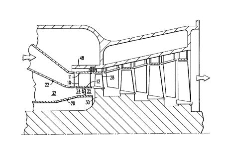
1. A gas turbine of the type having a turbine cylinder
containing a plurality of stationary vanes and rotating
blades, said vanes and blades defining an annular flow
path therebetween, said vanes circumferentially disposed
in a row surrounding a rotating shaft and extending into
said annular flow path;
each of said vanes having a radially inboard end,
there being an inner shroud at each of said radially
inboard ends;
each of said inner shrouds having first and second
approximately axially oriented edges, said first and
second edges of each pair of adjacent inner shrouds
forming a circumferential gap, a slot being formed in each
of said first and second edges;
each of said inner shrouds having inner and outer
surfaces, said inner surfaces of said inner shrouds
forming a shroud cavity;
a supply of high pressure air to said shroud cavity;
means for regulating the leakage of said high
pressure air from said shroud cavity through each of said
circumferential gaps between adjacent inner shrouds,
characterized by:
a strip seal for each of said circumferential gaps.
each of said strip seals having two longitudinal edges;
a sealing surface along each of said longitudinal
edges, said sealing surfaces of each of said strip seals
residing in said slots of two of said inner shrouds which
are adjacent, one of said sealing surfaces residing in one
of said slots and the other of said sealing surfaces
residing in the other one of said slots whereby each of
said strip seals spans one of said circumferential gaps;
and
a plurality of intermittent reliefs in each of said
sealing surfaces, the size and quantity of which being
variable to obtain the leakage flow desired.
2. A gas turbine according to claim 1 wherein each of
said strip seals comprises a dumbbell-shaped cross-section
having cylindrical portions, each of said cylindrical
portions extending the length of each of said seals, the
diameter of said cylindrical portions being approximately
that of the width of said slots, thereby forming said
sealing surfaces.
3. A gas turbine having a turbine cylinder containing a
plurality of stationary vanes and rotating blades, said
vanes and blades defining an annular flow path
therebetween, said vanes circumferentially disposed in a
row surrounding a rotating shaft and extending into said
annular flow path;
each of said vanes having a radially inboard end,
there being an inner shroud at each of said radially
inboard ends;
each of said inner shrouds having first and second
approximately axially oriented edges, said first and
second edges of each pair of adjacent inner shrouds
forming a circumferential gap, a slot being formed in each
of said first and second edges;
each of said inner shrouds having inner and outer
surfaces, said inner surfaces of said inner shrouds
forming a shroud cavity;
a supply of high pressure air to said shroud cavity;
a radial barrier extending circumferentially around
said shroud cavity and extending into said shroud cavity,
said radial barrier restricting the flow of said high
pressure air supplied to said shroud cavity from flowing
downstream past said barrier, said radial barrier having
front and rear faces, a portion of each of said
11
circumferential gaps being downstream of said radial
barrier;
means for distributing said high pressure air to said
portion of each of said gaps downstream of said radial
barrier, comprising:
means for regulating the leakage of said high
pressure air from said shroud cavity through each of said
circumferential gaps, said regulating means disposed in
each of said circumferential gaps and retained in said
slots in said first and second axially oriented edges of
said inner shrouds;
a plurality of holes in each of said inner shrouds,
a portion of said holes in each inner shroud extending
from said inner surface to said slot in said first
approximately axially oriented edge and remaining portion
of said holes extending from said inner surface to said
slot in said second approximately axially oriented edge;
a plurality of holes in said radial barrier,
extending from said front to said rear face to said
barrier; and
a manifold for each of said inner shrouds, each of
said manifolds connecting each of said holes in said
radial barrier to said holes in its respective inner
shroud.
4. A gas turbine according to claim 3 wherein the size
of said holes in said radial barrier are variable to
obtain the leakage flow desired.
5. A gas turbine according to claim 3 wherein each of
said manifolds comprises a containment cover, each of said
containment covers affixed to said inner surface of its
respective inner shroud.
6. A gas turbine according to claim 3 wherein said
radial barrier is comprised of a plurality of support
12
rails, one of said support rails emanating from said inner
surface of each of said inner shrouds.
7. A gas turbine comprising:
a plurality of vanes, said vanes arranged in a
circular pattern so that each of said vanes has tow other
of said vanes adjacent to it, each of said vanes having a
radially inboard end;
an inner shroud at said radially inboard end of each
of said vanes, each of said inner shrouds having two
approximately axially oriented edges, said approximately
axially oriented edges of each pair of adjacent inner
shrouds forming a circumferential gap, each of said
shrouds having first and second portions;
a high pressure air supply, said high pressure air
supplied to said first portion of each of said inner
shrouds, said second portion of each of said inner shrouds
not supplied with said high pressure air;
a plurality of slots, one of each of said slots
disposed in each of said approximately axially oriented
edges of said inner shrouds;
a strip seal for each of said circumferential gaps,
each of said strip seals having two longitudinal edges,
each of said edges forming a sealing surface, each of said
strip seal disposed in its respective circumferential gap,
each of said sealing surfaces being retained in said slots
whereby each of said strip seals spans its respective
circumferential gap, a portion of each of said strip seals
being located in said second portion of each inner shroud;
at least one relief in each of said sealing surfaces;
and a plurality of manifolds connecting said high pressure
air to said portion of each of said strip seals located in
said second portion of each inner shroud.
8. A gas turbine of the type having a turbine cylinder
containing a plurality of stationary vanes and rotating
blades, said vanes and blades forming an annular flow path
13
therebetween; a plurality of stationary members
circumferentially arranged in a row surrounding a rotating
shaft and forming a portion of said annular flow path,
each of said stationary members being separated from each
adjacent stationary member by a gap formed therebetween;
and regulating means for regulating leakage through said
gaps, said regulating means comprising:
a plurality of strip seals, each of said strip seals
disposed in one of said gaps, each of said strip seals
having first and second substantially longitudinal edges,
a sealing surface along each of said longitudinal edges,
each of said sealing surfaces having at least one relief,
the size of said at least one relief being variable to
obtain the degree of leakage desired, each of said sealing
surfaces along said first longitudinal edges being in
contact with one of said stationary members, each of said
sealing surfaces along said second longitudinal edges
being in contact with said adjacent stationary member
forming said gap, whereby each of said strip seals spans
one of said gaps.
9. A gas turbine according to claim 8 wherein said at
least one relief comprises a plurality of intermittent
reliefs in each of said sealing surfaces.
10. A gas turbine according to claim 8 further comprising
first and second approximately axially extending edges
formed in each of said stationary members, there being a
slot in each of said axially extending edges, each of said
longitudinal edges of said strip seals being disposed in
one of said slots.
11. A gas turbine comprising a turbine cylinder
containing an annular flow path, an annual cavity and a
rotating shaft; a plurality of stationary members
separating said annular flow path from said annular
cavity, said stationary members circumferentially arrayed
14
around said rotating shaft; each of said stationary
members being separated from each adjacent stationary
member by a circumferential gap; a radial barrier
extending circumferentially around said a annular cavity
and dividing said annular cavity into first and second
portions; first and second leakage paths between said
second portion of said annular cavity and said annular
flow path, said second leakage paths being formed by each
of said circumferential gaps; means for regulating leakage
of high pressure air through each of said second leakage
paths, said regulating means comprising a seal with
reliefs for leakage of air therethrough; a supply of high
pressure air to said first portion of said annular cavity;
and means for flow communication of said high pressure air
between said first portion of said annular cavity and each
of said second leakage paths, said flow communication
means having means for preventing said high pressure air
in said flow communication from communicating with said
second portion of said annular cavity.
12. A gas turbine according to claim 11 wherein said
stationary members comprise stationary vanes disposed in
said annular flow path, each of said vanes having a
radially inboard end, said stationary members forming an
inner shroud at each of said radially inboard ends.
13. A gas turbine according to claim 11 further
comprising a housing encasing said rotating shaft and
forming a portion of said annular cavity, said radial
barrier extending from each of said stationary members to
said housing, thereby preventing flow of said high
pressure air from said first to said second portions of
said annular cavity.
14. A gas turbine according to claim 13 wherein said
means for flow communication comprises a plurality of
holes in said radial barrier and a manifold for each of
said stationary members, each of said manifolds being in
flow communication with one of said holes and one of said
second leakage paths.