Note: Descriptions are shown in the official language in which they were submitted.
:L3~3~
TISSU~ OR MUCUS SAMPLING DE~ICE
Background of th~ Invention
The present invention relates to a sampling
device for obtaining a tissue or mucus sample from the
cervical os or from the upper region of the vagina (vaginal
fornix) without undue contamination of the sample by
vaginal fluids.
Collection of cervical material in the ~orm of
tissue and mucus has been routinely performed for many
years. Such retrieved samples are then tested for
malignancy by the Pap test or examined for various purposes
such as to determine whether ovulation has occurred.
The probes or devices generally used to obtain
such cervical samples for examination and testing have not
been designed for self-use by women wishing to collect
cervical specimens at home. In most instances, skilled
medical personnel obtain the required samples ~or testing.
Some recent patents disclose sampling devices designed
specifically for self-use by women.
U.S. Patent 3,592,186 relates to an apparatus for
self-use in the collection of cervical samples for
evaluation. The apparatus comprises a substantially
resilient scraper having a generally irregular heart-shape
telescopically engaged within a protective cover. ~hen the
apparatus is disposed substantially within the female body
at the vaginal opening, the scraper is extensible and
rotatable by the individual from whom the sample is to be
obtained. An indexer is provided to give external
indication to the operator of the relative position of the
scraper when in operation.
-2- ~ 9 ~ 3 ~
U.S. Patent 3,776,219 discloses a cervical
scraper unit designed particularly for utilization by the
female hersel. The scraper comprises a conical
polyurethane foam head cantilevered at the end of a hollow
plastic tube and enveloped by a plurality of protective
flexible petal-like appendages. The head is mounted to be
exposed by the petals at the testing site, and to
accommodate its collapse and flexion when it is rotated in
situ against the entrance to the cervix. Subsequently, the
petals are arranged to envelop and protect the head during
withdrawal. The ability of the scraper to collapse and to
flex, its resilient nature, and its conical shape, along
with the protection of the sample by the petals, are all
said to contribute to the efficiency and completeness of
transfer of a collected sample for examination.
U.S. Patent 4,131,112 provides a probe for
obtaining a sample of cervical mucus which comprises a
syringe-like structure characterized by an outer barrel and
an inner plunger capable of producing relative peristaltic
motion. The cooperating forward configurations of the
outer barrel and the inner plunger defines therebetween the
specimen cavity which, when it is caused to increase in
volume with rearward motion of the plunger, receives a
fluid specimen through the forward opening under suction
and when it is caused to decrease in volume with forward
motion of the plunger, ejects the fluid specimen through
the forward opening under pressure.
U.S. Patent 4,157,709 and U.S. Patent 4,318,414
disclose probes for inserting a test element into the
vaginal cavity while shielding it from intermediate vaginal
contact, for positioning the test element in contact with
the cervical os with the aid of a reference foot, in order
to collect a specimen of cervical material and for
retrieving the test element and the specimen from the
vaginal cavity while shielding them from intermediate
vaginal contact.
~ 3~3~
3 60557-3712
Other devices ~or collecting samples o~ cellular
cervical material are disclosed in U. S. Patents 3,6~0,268 and
3,664,328.
Summarv of the Invention
The present invention provides a tissue or mucus
sampling device for obtaining a tissue or mucus sample from ~he
cervical os or the vaginal fornix comprising a one-piece elon~ate,
cylindrical outer protective sleeve terminating ln a tip,
positionable guard means on said protective sleeve for limiting
the insertion depth of said device into the vaginal cavity, an
elongate, cylindrical insertion tube having a first end and a
second end telescopically fitting within said protective sleeve,
surmountable stop means on said insertion tube for temporarily
inhibiting said first end of said insertion tube from protruding
through said protective sleeve, stop means on said insertion tube
for permanently limiting the exten~ of protrusion of said tube
beyond said sleeve, a tissue or mucus sampling member on said
first end of said insertion tube and a handle member affixed to
said second end of said insertion tube for manipulating said tube.
The sampling device enables a woman to obtain a sample of tissue
or mueus from the cervical os or from the va~inal fornix for
examination and testing. The device is extremely simple in design
and easy to use.
Brlef ~
Figure 1 is a perspective view of the device of the
present invention in an unassembled position;
Figure 2 is a side view, partly in section, of the
device of Figure ~ in its "in use" position;
.~
3 ~
3a 60557-3712
Figure 3 is a perspective view of an embodiment of the
device of the present invention in an unassembled posltion;
Figure 4 is a side view, partly in section, of the
device of Figure 3 in its "insertion" position;
Figure 5 is a side view, par-~ly in section, of the
device of Figure 3 in its "collection" position; and
Figure 6 is a partial perspective view of an insertion
tube having a scraper as the tissue or mucus sampling member.
Detailed Descripti_n of the Invention
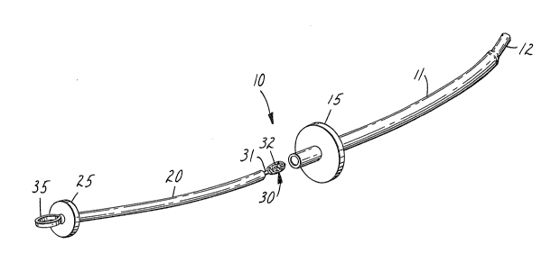
Re~erring now to the drawings, tissue or mucus sampling
device 10 comprises an outer protective sleeve 11, a guard means
15, a telescoping insertion tube 20, a stop means 25 and a tissue
or mucus sampling member 30.
' ~
_4_ ~3~
As used throughout the specification, the term
"cervical" when used to refer to a mucus sample should be
understood to include a mucus sample obtained from the
upper region of the vagina ~the vaginal fornix).
Protective sleeve 11 is a one-piece elongate
cylinder or tube formed of any material of relatively low
liquid absorbency with a low coefficient o~ friction and
non-irritating to the human skin, such as stainless steel.
Preferably, protective sleeve 41 is formed of a semi-rigid
polymer, such as polyvinyl chloride, polypropylene,
polyethylene, polyethylene terephthalate, polycarbonate,
Teflon or Nylon. The protective sleeve 11 pre~erably is
inclined from the horizontal at an angle of from 15 to
45. In the case of a protective sleeve 11 formed of a
preferred material as described above, this angle may be
imparted by thermal treatment. Inclination of tip 12 from
the horizontal facilitates the process of obtaining a
sample either from the cervical os or from the vaginal
fornix due to the anatomy of the cervix relative to the
vaginal cavity. In the thermal treatment process, sleeve
11 is drawn so that sleeve 11 is gently tapered along its
length and tip 12 has a greatly reduced diameter, as
clearly seen in the drawings. The resulting reduced
diameter of tip 12 assists in minimizing contamination of
the cervical mucus sample with vaginal fluids particularly
during insertion of the device 10. Protective sleeve 11
can also be injection molded into the desired
configuration. It will be appreciated that protective
sleeve 11 can also be a straight cylinder or tube with only
the tip portion inclined at the desired angle and such an
arrangement is contemplated.
Guard means 15, formed of a suitable polymeric
material, is tightly frictionally fitted onto protective
sleeve 11 for sliding movement therealong. Since guard
means 15 functions to limit the depth of insertion of
device 10 into the vaginal cavity, the sliding movement of
guard means 15 on sleeve 11 is accomplished only with some
effort.
_5_ ~3~9~3~
nsertion tube 20 is an elongate cylinder or tube
~ormed of any of the same materials as protective sleeve
11, or alternatively is formed of a different ~aterial that
is sufficiently resilient to be insertable through
protective sleeve 11, such as polystyrene or paper. When
insertion tube 20 is formed oE an absorbent material, it
should be discarded after use. As shown in the drawings,
insertion tube 20 has an outer diameter slightly smaller
than the inner diameter of protective sleeve 11 to permit
it to telescopically fit and slide within protective sleeve
11. Insertion tube 20 can, of course, be in the form of a
rod.
Stop means 25, preferably formed of a suitable
polymeric material, is also tightly frictionally fitted
onto insertion tube 20 in like manner as guard ring 15 on
protective sleeve 11. Stop means 25 serves to limit the
degree of protrusion from tip 12 of the cervical tissue or
mucus sampling member 30. Stop means 25 may also be
integrally formed as an integral part of insertion tube 20
particularly when insertion tube 20 is in rod form.
As will be seen in Figure 2, cervical tissue or
mucus sampling member 30 is illustrated as a double-ended
swab comprising an elongate semi-rigid rod 31, the ends of
which are covered with a flexible, soft, resilient ~ibrous
material such as cotton, rayon, polyester or calcium
alginate, forming specimen collecting tips 32. It has also
been found that foam materials, particularly open cell foam
materials, are highly efficient as sampling member 30.
Only one of tips 32 is used for collecting a mucus sample.
The other tip 32 serves to frictionally hold sampling
member 30 firmly in the interior of insertion tube 20. It
will be readily apparent to the reader that the end of
sampling member 30 inserted into insertion tube 20 can take
other forms than shown, e.g., the rod 31 can be of a larger
diameter or an elastomeric collar can be placed over the
rod end. When sampling member 30 is to be used to collect
a tissue sample, the tip pf sampling member would be in the
form of a scraper.
-6- ~3a~3~
A handle member 35, shown as a ring, is affixed
~o one end of insertion tube 20 and is used to guide
insertion tube 20 into protective sleeve 11 and also to
manipulate the sampling member 30 in insertion tube 20
during use of device 10.
After assembling device 10 by fitting a sampling
member 30 into insertion tube 20 and placing insertion tube
20 into protective sleeve`ll, stop means 25 is moved along
insertion tube 20 so that the tip 32 of sampling member 30
protrudes only slightly from tip 12. Insertion tube 20 is
then withdrawn a short distance (approximately one-hal~ to
one inch) to avoid contamination of tip 32 with vaginal
fluids. Device 10 is then inserted into the vaginal cavity
until tip 12 contacts the cervical os. Guard means 15 is
then moved into contact with the vaginal orifice to prevent
further insertion of device 10 into the vaginal cavity to
avoid possible injury to the user. Of course, if device 10
has previously been used for collecting a cervical sample,
guard means 15 would already be in the desired position on
protective sleeve 11. Insertion tube 20 is then pushed
forwardly into protective sleeve 11 by handle member 35
until tip 32 of sampling member 30 is in the predetermined
7'in use" position shown i~ Figure 2. Handle member 35 can
then be gently rotated to thus collect a mucus sample.
Insertion tu~e 20 is retracted a short distance and device
10 is then withdrawn. Protective sleeve 11 shields the
insertion tube 20 and particularly tip 32 of sampling
member 30 during the entire insertion and removal process.
Insertion tube 20 is completely withdrawn from protective
sleeve 11 and the collected mucus sample is available for
further processing for examination and testing.
After each use, device 10 is completely cleaned
by washing with soap and water and is ready for reuse.
Sampling member 30, if the mucus collecting swab was used
is discarded; if a scraper form was used, it is also washed
for reuse.
_7_ 13~
Figures ~, 4 and 5 show an alternative embodiment
of the tissue or mucus sampling device of this invention
40, comprising an outer protective sleeve 41, a gua~d means
45, an insertion tube 50, a stop means 55, a surmountable
stop means 57~ and a tissue or mucus sampling member 60.
Protective sleeve 41 is a one-piece elongate
cylinder or tube formed of any material of relatively low
liquid absorbency with a low coefficient of frlction and
non-irritating to the human skin, such as stainless steel.
Preferably, protective sleeve 41 is formed of a semi-rigid
polymer, such as polyvinyl chloride, polypropylene,
polyethylene, polyethylene terephthalate, polycarbonate,
A Teflon~or Nylon. The protective sleeve 41 preferably is
angled beginning at a position 47 which is located at about
one fifth of the length of the sleeve 41 ~rom the tip 48,
so that the tip 48 is inclined from the horizontal at an
angle of from 15 to 45 . In the case of a protective
sleeve 41 formed of a preferred material as described
above, this angle may be imparted by thermal treatment.
Most preferably, this angle is 22.5. Inclination of tip
4~ from the horizontal facilitates the process of obtaining
a sample eit~er from the cervical os or from the vaginal
fornix due to the anatomy of the cervix relative to the
vaginal cavity. Protective sleeve 41 can also be injection
molded into the desired configuration.
Guard means 45, formed of a suitable polymeric
material, is tightly frictionally fitted onto protective
sleeve 41 for sliding movement therealong. Since guard
means 45 ~unctions to limit the depth o~ insertion of
device 40 into the vaginal cavity, the sliding movement of
guard means 45 on sleeve ~1 is accomplished only ~ith some
effort.
Insertion tube 50 is an elongate cylinder or tube
formed of any of the same materials as protective sleeve
41, or alternatively is formed of a different material that
is sufficiently resilient to be insertable through
protective sleeve 41, such as polystyrene or paper. When
insertion tube 50 is formed of an absorbent material, it
rr,d ~e ~ lc
~3~3~
--8--
should be disearded after use. As shown in th~ drawings,
insertion tube 50 is in the form of a rod. Insertion tube
50 can be in the form of a sleeve having an outer diameter
slightly smaller than the inner diameter of protective
sleeve 41 to permit it to telescopically fit and slide
within protective sleeve 41.
Stop means 55, preferably formed of a suitable
polymeric material, is integrally formed with the insertion
tube 50. Rlternatively, the stop means 55 may be provided
as a separate piece which is tightly frictionally fitted
onto insertion tube 50 in like manner as guard means ~5 on
protective sleeve 41. Stop means 55 serves to limit the
degree of protrusion from the tip 48 of protective sleeve
41.
Tissue or mucus sampling member 60 is located at
the first end of the insertion tube 50. Tissue or mucus
sampling member 60 is illustrated as a specimen collection
tip made of a flexible, soft, resilient fibrous material
such as cotton, rayon, polyester or calcium alginate. It
has also been found that foam materials, particularly open
cell foam materials, are highly efEicient as tissue or
mucus sampling member 60.
When tissue or mucus sampling member 60 is to be
used to collect a tissue sample, the tip of tissue or mucus
sampling member 60 would be in the form of a scraper.
A handle member 65, shown as a disk, is affixed
to the second end of insertion tube 50 and is used to guide
insertion tube 50 into protective sleeve 41 and also to
manipulate the sampling member 60 in insertion tube 50
during use of device 40.
Surmountable stop means 57 is provided on
insertion tube 50 at a position a distance from the end of
tissue or mucus sampling member 60 which is less than or
about the same as the length of protective sleeve 41.
Surmountable stop means 57 temporarily inhibits the first
end of insertion tube 50 from protruding through protective
sleeve 41, thereby preventing the protrusion of tissue or
mucus sampling member 60 beyond protective sleeve 41 during
9 ~ 3 ~
insertion of collecting device 40 in the vagina. If tissue
or mucus sampling member 60 is not shielded, it will pick
up mucus from the wrong part of the vagina. It is
important that mucus be sampled only in the region of the
cervical os in order to provide an efective ovulation
indicator.
As shown in the drawings, surmountable stop means
57 is in the form o~ two protruberances, or "bumps", of
material of the same manufacture as insertion tube 50, one
bump on either side o~ insertion tube 50. Surmountable
stop means 57 alternatively can be in the form of a
widening of insertion tube 50, a ridge, a key and keyhole
mechanism wherein tabs on insertion tube 50 must be aligned
with slots in protective sleeve 41 to allow further
insertion of insertion tube 50 through protective sleeve
41, or any other means which would provide a temporary stop
in the insertion of insertion tube 50 into protective
sleeve 41. "Bumps" are preferred to a continuous ring
configuration because less friction is experienced after
surmountable stop means 57 has been overcome and during the
sliding action of insertion tube 50 through protective
sleeve 41, permitting easy operation of tissue or mucus
sampling device 40 in collection of a sample.
The cross-sectional distance between the outer
surfaces of surmountable stop means 57 as shown in the
figure at its widest portion is slightly larger than the
inside diameter of protective sleeve 41, so that upon
insertion of insertion tube 50 into protective sleeve 41,
surmountable stop means 57 will come into contact with edge
43 of protective sleeve 41 and prevent easy further
insertion into protective sleeve 41. For example,
surmountable stop means 57 may have a diameter at its
widest portion of about .217 inches while the inside
diameter of protective sleeve 41 is about .210 inches. A
slightly greater insertion force on handle member 65 will
overcome the resistance provided by the contact of
surmountable stop means 57 with edge 43 of protective
:~ 3 ~ '3 ~
-- 10 --
60557-3712
sleeve 41, allowing insertion tube 50 to be fully inserted into
protective sleeve 41 to the point where edge 43 of protective
sleeve 41 contacts stop means 55.
As seen in Figure 4, when surmountable stop means 57
is in contact with edge 43 of protective sleeve 41, tissue or
mucus sampling member 60 remains inside protective sleeve 41.
Optimally, t.ssue or mucus sampling member 60 is fully within
protective sleeve 41, and may be located even further within
protective sleeve 41 than shown by the figure by reducing the
distance between tissue or mucus sampling member 60 and
surmountable stop means 57.
Figure 5 shows tissue or mucus sampling device 40
where surmountable stop means 57 has been overcome by additional
insertion force at handle member 65, thereby fully engaging
insertion tube 50 within protective sleeve 41. Tissue or mucus
sampling member 60 protrudes at least partially from protective
sleeve 41, enabling a sample to be taken.
Figure 6 shows an alternative tissue or mucus sampling
device configuration wherein insertion tube 70 is provided with
scraper 71 as the tissue or mucus sampling member~
Tissue or mucus sampling device 40 is assembled by
fitting tissue or mucus sampling member 60 onto insertion tube 50
and sliding insertion tube 50 into protective sleeve 41 until
surmountable stop means 57 contacts edge 43 of protective sleeve
41. Tissue or mucus sampling device 40 will have been premeasured
and manufactured so that when surmountable stop means 57 is in
contact with edge 43 of protective sleeve 41, tissue or mucus
sampling member 60 remains inside protective sleeve 41 to avoid
- lOa - 13Q ~
60557-3712
contamination of tissue or mucus sampling member 60 with vaginal
fluids or mucus.
Tissue or mucus sampling device 40 is then inserted
into the vagi.nal cavity until tip 48 contacts the cervical os.
Guard means 45 is then moved into contact with the vaginal
orifice to prevent further insertion of tissue or mucus sampling
device 40 into the vaginal cavity to avoid possible injury to
the user. Of course, if tissue or mucus sampling device 40 has
previously been used for collecting a cervical sample, guard
means 45 would already be in the desired position on protective
sleeve 41.
Insertion sleeve 50 is then pushed forwardly into
protective sleeve 41 by handle member 65 until tissue or
mucus sampling member 60 is in the predetermined "in use"
position shown in Figure 5. Handle member 65 can then be
gently rotated to thus collect a mucus sample. Insertion
tube 50 is retracted a short distance, at least beyond
surmountable stop means 57, and tissue or mucus sampling
device 40 is then withdrawn. Protective sleeve 41 shields
insertion tube 50 and particularly tissue or mucus sampling
member 60 during the entire insertion and removal process.
Insertion tube 50 is completely withdrawn from protective
sleeve 41 and the collected mucus sample is available for
further processing for examination and testing~
After each use, device 40 is completely cleaned
by washing with soap and water and is ready for reuse.
Tissue or mucus sampling member 60, if the mucus collecting
swab was used, is discarded; if a scraper form was used, it
is also washed for reuse.
When conducting in vivo testing of ovulation
prediction, swabs made of hydrophilic polymer or swabs with
hydrophilic polymer coated surfaces provide better cervical
mucus sampling than other types of materials. The best
forms include an open cell foam structure and surfaces with
many capillary openings. Their surfaces provide good
adsorption of the mucus sample, but also free release of
the sample during the subsequent extraction. To illust~ate
this, the following experiment was performed:
0.15 ml samples of cervical mucus were dropped
onto pads of the fibrous test materialsO After a one
minute delay to allow the mucus to be completely absorbed,
the fibrous test materials were extracted in an aqueous
solution consisting of a buffer, and a reactive mixture
that gave a colorimetric reaction in the presence of an
enzyme in the mucus. Thejcolor change could be read
quantitatively after two minutes as an optical absorbence
at 470 nm, and is indicative of the quantity of mucus
extracted. As a control, a 0.15 ml sample was added
directly to a sample of the reactive mixture and its
absorbence read after two minutes at 470 nm.
3 ~
-12-
The ratio defined below gives the sample-release
efficiency of the swab, i.e.,
efficiency = A470nm
~470nm x 100~
where A: optical absorption of solution after
test swab was coated with fixed amount
of cervical mucus and was subsequently
extracted and reacted;
and B: optical absorption of solution with
fixed amount of cervical mucus added
directly to the buffer reaction
mixture.
Sample-Release
Material Description Efficiency %
Thermal bonded polyester web (3M) 106
Polyacrylonitrile web (Du Pont Orlon) g9
Polyurethane open cell foam (Scott Foam
Division of Scott Paper Company) 92-87
Rayon web (3M) 82
Hydrophilic polyurethane foam
(Polyurethane prepolymer derived
from toluene diisocyanate) (3M) 74
Cotton, Polypropylene, Polyester
bicomponent web (3M) 74-61
Rayon fiber (PurFybr, Inc.) 67
Calcium alginate fiber, Polyester
fiber (PurFybr, Inc.) 57-47
Polyethylene closed cell foam
(Scott Foam Division of Scott Paper
Company) 33
For the ovulation prediction test, the preferred test swab
material is the polyurethane open cell ~oam, because of its
availa~ility, low cost, low toxicity, ease of manufacturing
and the described release efficiency.