Note: Descriptions are shown in the official language in which they were submitted.
130~37~0 21427-152
This invention relates to an agglomeration device
and, more particularly, to the pin construction and casing
thereof.
BACKGROUND OF THE INVENTION
Agglomeration devices, in the past, have developed
serious problems, such as the tendency of breakage of the
radially extending pins as they rub against very dense layers
of material being mixed which tend to virtually weld to the
inner surface of the steel cylindrical body. Attempts have
been made by building in scrappers but these have consumed
considerable electrical power and have not solved the problem
since once the layers are formed they are extremely difficult
to scrape.
SUMMARY OF THE INVENTION
According to a broad aspect of the present inven-
tion there is provided in an agglomeration device having a
driven shaft and a plurality of pins extending radially out-
wardly thereof of such length as to sweep closely to the inner
surface of the casing of said device; the improvement comprising
a layer of high density plastic material attached to the inner
surface of said casing, each pin having a ceramic sleeve.
DETAILED DESCRIPTION OF THE DRAWINGS
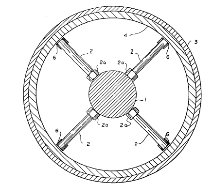
Figure l shows a vertical cross-section of an
agglomeration device embodying the present invention;
Figure 2 is an enlarged, fragmentary cross-section
showing one way of attachment of the inner lining to the
casing; and
Figure 3 shows a fragmentary, perspective view of
the device shown in Figure 1.
-- 1 --
~ 3 0 ~ 7 1 0 21427-152
DETAILED DESCRIPTION OF THE PREFERRED EMBODIMENT
Referring more particularly to Figure 1, numeral
1 denotes a rotating shaft of metal driven by any suitable
motor means (not shown), which shaft has screw threadedly
attached thereto pins 2 extending radially outwardly of the
shaft and fastened thereto by bolts 2a.
The outer end portions of the pins 2 are provided
with a ceramic sleeve 6 made of a very hard material such as
alumina, tungsten carbide, silicon carbide or boron carbide.
Said ceramic sleeve is flush with the end of said pin 2 and
increases the diameter of the end of said pin
- la -
13~1~7~L~
allowlng greater coverage of the liner surface. For example, a 1/2
inch diameter pin might have a 1/4 inch thich ceramic sleeve which would
provide a 1 inch diameter coverage of the liner surface. The tip speed
is between 3000 and 5000 feet per minute to enable pelletizing reaction
to take place for certain materials.
While only 4 pins are shown in a circular path, 6 or 8 or any
other number may be used instead. The pins may be of heat treated steel
to at least 15000 psig yield and a hardness of 32 to 38 Rockwell C.
An important feature of the invention is that the pins are
displaced axially of the shaft 1 by the diameter of each pin so as
to completely cover the inner surface area of the lining with an
additional overlap relative to the thickness of the ceramic sleeve 6.
To the ;nner surface of the cylinderical steel body or casing
3 there is attached a lining 4 by any suitable means, such as that
shown in Fig. 2, namely by bolts 5 extending through holes formed in the
lining 4 in such mannor as to not cause engagement of the bolts with
the tips of pins 2, as shown in Fig. 2.
Lining 4 is made of high density resistant plastic material, such
as 80-85 durometer polyurethane, which may be, instead, cast in place.
The clearance between the tips of the pins and the lining is
critical and should be less than 1t16 of an inch. The lining will
actually yield on the slightest accumulation of material, either on the
tips of the pins or on the inner surface of lining 4. Other lining
materials having characteristics similar to polyurethane may be
used for example: rubber, neoprene, red rubber silicon or "viton".
Thus it will be seen that I have provided a highly efficient
agglomeration device and, more particularly, the construction of the
outer ends of the pins and the inner surface of the casing to minimize
or prevent any tendency of breakage of the pins as the result of sticking
to accumulated layers in the outer surface of the casing, also which
provides a great savings in power previously used for scraping, by
electrically driven mechanical means, the accumulated layers on the
inner surface of the casing.
130~7~
While I have illustrated and described a single specific
embodiment of my ;nvent;on, ;t w;ll be understood that this is by
way of illustration only and that various changes and modificatlons
may be contemplated in my ;nvention w;th;n the scope of the follow;ng
claims.