Note: Descriptions are shown in the official language in which they were submitted.
~ 3~3~
~ hi~ invention relate~ to dilution in the analysis of a
liquid and more partioularly the means and method o~ controlling the
dilution of the liqllid to be analyzed.
This application dioolo~e~ apparatus and method di~closed
and claimed in applicant's oo-pending Canadian Applioation Serial No.
537,505, filed May 20, 1987 for "Analyzing Apparatu~ and Method for
Analysi~ of Liquid Sample~
BACKGROUND OF ~HE INVENTION
Small volume~ of liquid sample3 are analyzed in a detector
whioh ~en~es oharaoteri~tio~ of the liquid ~ample and reoord~ the
information. The sample liquid is seleotively in-troduoed into the
deteotor and individually analyzed by senslng and meaauring and the
information i~ rapidly reoorded.
In proce~aing the liquid ~ample through the deteotor the
sample liquid i~ diluted in a diluting liquid and the prooes~ing of
the sample liquid and it~ analy~is takes place with the ~ample liquid
oarried in a diluent.
The amount of dilution of the ~ample liquid in the diluent
is oontrolled. Among other rea~onc for exerGise of the oontrol of the
sample liquid i~ its oon~ervation or that of the reagent. ~hi~ io
partioularly important in an in~tanoe when the available volume of
~ample liquid is limited.
pg/~
`~
~ 3 ~
srief Description of the Inventian
In many automated chemical analysis systems the sample
to be analyzed must be diluted, mixed with reagents, and passed
on to a suitable sensor. The objects of this invention relate
to the control, automation and fine tuning of the dilution
process of such syst~ms.
Among other objects of the present invention is a
fine degree of control of the amount or percentage of dilution
of the sample liquid in a diluent.
Another object of the invention is attaining a high
percentage of dilution of the sample liquid in the diluent.
A still further object of the invention is the provision of
an effective dilution apparatus of simple construction which
is easy to manufacture and use.
In general, in operation the sample liquid is passed
through a non-wetting porous membrane from a reservoir of sample
liquid to a flowing stream of diluent which is constantly flowing
when the sample liquid penetrates the membrane under positive
pressure differential from the sample side of th~e membrane.
The pressure differential is suitably obtained both by means
for exerting pressure on the sample liquids as for example
on a stream of sample liquid on the entry side of the me~brane
as well as a redu~tion in pressure on the exit side of the
membrane.
The passage of the sample liquid through the non-
wetting porous membrane requires a minimum liquid entry pressure
differential, hereinafter referred to as MLEPD, across the
membrane to cause penetration through the po~es and not the
material. This MLEPD must be enough to give a penetration
of sample liquid whlch provides in the analyzed diluent stream
a detectable
~ 3~3~
presence of the sample liquid in an analytical detector receiving
and measuring the stream.
The invention will become more apparent upon considera-
tion of the following detailed descxiption taken together with
the drawings,
Description of the-~awings
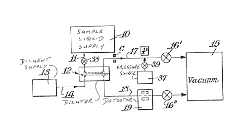
Fig, 1 is a block diagram illustrating the apparatus
and system embodying the present invention;
Fig, 2 is a side elevation partly broken away of
the diluter assembly of this invention;
Fig, 3 is a sectional view of the diluter as illustrated
in Fig, 2 taken on line 3-3 of Fig, 2 and rotated 90 counter
clockwise;
Fig. 4 is a bottom plan view of the top plate of
the diluter;
Fig, 5 is a top plan view of the bottom plate of
the diluter;
Fig. 6 is a sectional view of a portion of the tubing
conveying the stream of liquid sample;
Fig, 7 is a schematic diagram for explaining the
functions of a means for controlling the pressure of the sample
liquid on the membrane;
Fig, 8 is a sectional view of a T-joint in the tubing
for conveying the sample liquid;
Fig, 9 is a graph diagrammatically illustrating the
operation of the present invention in an apparatus with a specific
sample liquid and membrane; and
Fig, 10 .is a graph diagrammatically illustrating
the operation of the present invention in an apparatus with
a specific sample liquid and another specific membrane,
Detailed Description of the Invention
It will be understood that sample liquid as
referred to herein refers to samples and reagents and
other inputs as disclosed in Serial No. 537,505 filed
May 21, 1986 as identified above.
Reservoir as used herein refers to a part of
the apparatus in which a sample liquid is held. In the
illustrated embodiment the reservoir is that part of
this apparatus which is positioned between valves 38
and valve 16l and includes a por-tion of conduit 11, the
chamber 20 in diluter 12, port 30 and that portion of
line 17 which connects port 30 with valve~16'.
In the apparatus of this invention samples
and reagents are processed to form a stream of sample
liquid which flows through the system to a detector
which senses and determines properties in composition
of the sample liquid. In Fig. 1, samples and reagents
are provided from a supply means 10 to form a flowing
liquid stream. The structure designated by the numeral
12 is a diluter. The diluter 12 is positioned to
receive the flowing stream of sample liquid and a
diluent stream transported from a diluent supply 13
through a line 14. In the diluter 12 a portion of the
sample liquid is combined with the diluent to form a
diluted liquid sample, which is transported from the
diluter 12 through a line 18. The remainder of the
sample liquid not transported to the diluent is
expelled through line 17. The flowing streams are
transported through the system by a driving force
supplied either by a vacuum 15 or by a positive
pressure Eorce. The vacuum is connected to the end of
the system through vacuum valves 16' ~and 16". A
positive pressure source would be similarly connected
through valves but in such a way as to push the sample.
The valves
sd/sp _4_
:
.
~ 3 ~
are open to dri~e the liquid stream through the system. A
representative system is disclosed in copending application
Serial No. 537, 505 by David Davidson et al and particularly
reference may be had to FigSD 5A, 5B and pages 12-16 in this
copending application.
In Fig. 1 the sample liquid in the sample stream
moves from the supply 10 into the diluter 12 through line 11
and controlled portion is forced from a reservoir formed in
the diluter 12 and line 17 into the diluent as described
below. On being withdrawn from the diluter 12 through line
18, the diluted liquid sample i5 passed through a detector
device, such as photometric detector 19. The transport of
the liquid streams through lines 11, 17 and 18 and diluter 12
is controlled by valve 16~ in line 17 and valve 16N in line
18. In a normal operational sequence of the system of Fig. 1
the driving pressure difference may be in the ran~e of 2% to
15 inches of mercury. The valves 16' and 16" are suitable
valves.
The structure of the diluter 12 is illustrated in
Figs. 2, 3, 4 and 5 and contains two small chambers 20 and 21
in a housing 22, which chambers 20 and 21 are separated by a
laterally extending membrane 23. A suitable membrane 23 is a
"~ore-Tex~ membrane" with a 1.0 micron pore size supported on
a non-woven polypropylene sheet.
Referring to Fig. 2 the diluter 12 is shown in front
elevation with the housing 22 partly broken away. The
housing 22 has a top plate 24 in which is seated a sealing
ring 25 in a groove 26 formed in the top plate 24. The
housing 22 has a bottom plate 27 joined to and abutting the
top plate 24. Chamber 20 is formed in top plate 24 and
chamber 21 is formed in bottom plate 27 and the chambers 20
and 21 meet when the plakes 24 and 27 are joined together.
rn/
~ 3~S3~
Fig. 4 is a bottom plan view of the top plate
2~ separated Erom the assembly in the housing 22. This
plan view shows a planar surface 33 forming the face of
plate 24 which interfaces with the bottom plate 27.
The membrane 23 extending across the surface 33 is
partly broken away to reveal the sealing ring 25. The
sealing ring 25 in turn is partly broken away to
illustrate its positioning in the groove 26. Ports 30
and 46 are shown in broken lines.
At the right side of Fig. 2 in the broken
away area the chamber 20 and an end of the port 30
opening into the chamber 20 can be seen in full lines.
To the left the remainder of the chamber is shown in
broken lines thus illustrating the narrow elongated
shape of the chamber 20.
Fig. 5 is a top plan view of the bottom plate
27 separated from assembly in the housing 22. This
plan view shows a planar surface 35 forming the face of
plate 27 which interfaces with the top plate 24. The
narrow, elongated chamber 21 is shown and the ends of
the port 29 and port 36 opening into the chamber 21 are
shown.
The membrane 23 and the sealing ring 25 are
positioned between the joined plates 24 and 27. The
membrane 23 extends laterally between the chambers 20
and 21 so as to separate the chambers 20 and 21 frorn
each other while providing with its porosity, passage
for a liquid from the chamber 20 to chamber 21. The
broken away section of plates 24 and 27 shown at the
right of center in Fig. 2 illustrates the interface
between the joined plates 24 and 27 at the right end of
chambers 20 and 21. An edge of the membrane 23
extending under the sealing ring 25 is clamped beneath
the sealing ring between the plates 24 and 27. The
clamping action serves to both secure the membrane 23
in position between chambers 20 and 21 and to provide a
sd/sp -6-
, ` , '' ~ .
7 ~3~3~
fluid tight seal against seepage of the liquids. The plates
24 and 27 are tightly clamped together by bolts 28 in Fig. 2
and bolts 28' in Fig. 3. In Fig. 2 the heads of bolts 28 ars
shown at plate 24. In Fig. 3 the heads of bolts 28' are
shown at plate 27.
Fig. 3 is a section taken from the right side of
Fig. 2 on line 3-3 across Fig. 2. In Fig. 3 the diluter 12
is turned at right angles to the orientation in Fig. 2. The
bottom plate 27 is on the left side and the top plate 24 is
on the right side in the housing 22 as illustrated in Fig. 3.
The chambers 20 and 21 a~ the center of the housing
22 are shown separated by the membrane 23 which is shown in
cross-section. A port 29 provides a passageway to the
chamber 21 in the bottom plate 27 while a port 30 provides a
passageway to the chamber 20. Nipples 31 and 32 screwed into
threaded recesses of the plates 27 and 24 respectively
connect lines 18 and 17 to the ports 29 and 30 respectively.
Thus, Fig. 3 illustrates the means for egress of the fluid
stream from the diluter 12.
According to this invention the membrane 23 is
distinguished by a non-wetting characteristic with respect to
the sample liquid and the diluent. This non-wetting
characteristic is a factor in the passage of the sample
liquid through the membrane. Another factor is the force or
pressure exerted on the sample liquid at the sample side of
tne membrane 23.
A non-wetting porous membrane is used to separate
the process stream of sample liquid from a diluent stream.
Since the membrane is not wet by the process stream liquid or
the diluent, the normal forces of capillary action which
would draw liquid across membrane, in either direction, are
not operative. Thus liquid must be forced across the
membrane by an external means such as an applied pressure
differential (This applied pressure differential may be
created by a positive
'.` rn/
:' '
3 ~ ~
pressure source for example, reservoir or pump, or by a suitably
configured and applied vacuum system.) In this application,
the sample stream is forced through the membrane into the flowing
diluent stream by the application of positive pressure in excess
of MLEPD on the sample reservoir. The rate of transport into
the diluent is a function of the membrane porosity, the wetting
characteristics of the membrane as expressed by the MLEPD,
the exposed surface area of the membrane, the pressure applied
to the liquid to drive it across the membrane, and the pressure
gradient in the diluent stream.
The total resistance to flow in any fluid path is
an important component of the liquid transport. Thus, the
resistance to flow across the membrane is dictated by the pore
size and distribution within the membrane, the wettability
of the membrane and any resistance to flow experienced by the
liquid on its path to thè membrane. For instance, a restric-
tion in the tube through which the liquid passes will contri-
bute to this resistance.
The pressure is applied to the sample liquid, according
to the present embodiment, through the line 17. A source of
pressure is represented in Fig. 1 by the block 37. To apply
the pressure on the sample liquid, the valve 16' is closed
and valve 38 in line 11 at the sample supply 10 is closed;
it is possible to provide a differential pressure across the
membrane 23 shown in Fig. 2 because the diluent is flowing
in a stream from the supply 13, therefore, providing an open
unrestricted path below the membrane. In the operation of
this invention the diluent must be flowing through the ~hamber
21 from the supply 13 to effect the passage of the sample fluid
through membrane 23. Moreover, the rate of transport across
--8--
~ 3 ~
the membrane is effected by the flow rate of the diluent. Thus
flowing of the diluent through the chamber 21 is a factor in
the dilution achieved by the present invention.
When the valves 16' and 38 are closed the reservoir
is formed and a positive pressure can be exerted from source
37 after opening valve 39. This pressure pushes against the
stream of the sample liquids in line 17 and in the chamber
20.
As pointed out above, according to this invention
the relationship between the sample liquid and the non-wetting
membrane is such that no transport of the liquid through the
membrane is possible without the application of at least the
MLEPD on the sample side of the membrane. When the applied
pressure equals or exceeds the MLEPD, flow across the membrane
results. The amount of dilution is a function of the applied
pressure. This functional relationship is employed herein
to provide a control of the percent of dilution of the sample.
It is possible to accurately control high percentages of dlluti~n.'
In some constructions of the apparatus of this invention,
the flow of the diluent stream across the membrane to a chamber,
such as chamber 21, may draw minute amounts of sample liquid
through the membrane, such as membrane 23, in the absence of
a minimum liquid entry pressure on the sample side of the membrane.
However, such transport is not accurately controllable and
accordingly such phenomenon should it occur is not capable
of contributing to the advantages of the present invention
as outlined in the statement of objects above.
It is a feature of the present invention that when
pressure is applied at P on the stream, the control of the
transport of the sample liquld from the reservoir penetrating
_ g_
through the non-wetting membrane 23 is augmented to an appre-
ciable degree. Thus, the amount of pressure influences the
quantity of flow through the membrane. Thus variation in the
exerted pressure is functionally related to the quantity of
,sample transported across the membrane 23 from the reservoir
and delîvered to the diluent chamber 21, as seen in Fig. 2.
The amount of sample provided into a volume of diluent in a
period of time is thus a function primarily of the characteristics
jof the membrane with respect to wetting and a variable applied
pressure. That is, MLEPD defines the minimum working pressure
on the reservoir on the sample side of membrane 23, i.e. at
chamber 20, which provides a transport to the diluent stream
to provide in the diluent stream of an amount of the sample
which is measurably detectable in the analytical detector 19.
Further, it will be seen that at pressures above
the MLEPD as determined by the characteristics of the material
of a membrane 23 r variations in pressure at P will influence
the amount of transported sample by changing the rate of transport.
Clearly this combination of factors provides a means for controlling
the amount of dilution of the sample in the diluent. However,
the effectiveness of the combination depends on the non-wetting
,characteristic of the membrane which is an essen~ial part of
the combination. As pointed out above, the present invention
requires a MLPED which is attributable to and derived from
the non-wetting characteristic of a membrane material as related
to a sample liquid.
Non-wetting as referred to here can be defined in
terms of the MLPED for the membrane as determined by the pressure
difference observed at which liquid penetration into the membrane
material has commenced. This can be carried out by a modification
~ 3 ~
of ASTM method D774-67 and the related TAPPI method T4030s-76.
Briefly stated in this technique, water and the tested membrane
are introduced into a Mullin Burst tester apparatus and hydrostatic
pressure on the water and the membrane is slowly increased.
The pressure at which droplets appear on the outside of the
test film is the minimum water entry pressure. Liquids other
than water may be used as appropriate to the selection of the
sample liquid to be diluted and the membrane to be used to
control this dilution. This pressure can be considered to
be the threshold of the operation according to this invention.
As explained below in greater detail, the threshold or MLEPD
is a property of the particular material of the membrane as
influenced both by the material compositions and the pore size
of the passages and porosity through the membrane material.
The passage of the sample liquid occurs only through the pores
of the material, not through the material itself. The membrane
of this invention as illustrated by membrane 23 in the figures,
is composed of a material having pores and porosity which with
a sample liquid is a non-wetting membrane. As used herein
this refers to a liquid not penetrating the membrane in the
absence of application of the MLEPD. Accordingly, the membrane
may be composed as such materials, as the Gore-Tex~ membrane
described below in the specific example with water as the sample
liquid ~r stainless steel with a suitable sample liquid.
The control of the mixture of the sample liquid in
the diluent according to this invention, is related to the
excess of the applied pressure beyond the MLEPD of the membrane
material. Pressures ranging above the minimum produce the
transport of the sample liquid through the pores of the membrane
in increasing amounts which vary as the function of the increase
~ 3 ~
in applied pressure in the sample liquid in the reservoir at
the sample side or chamber 20 as shown in ~ig. 2. This pressure
can be varied and controlled at P on line 17 from source 37
as shown in Fig. 1. It will be readily apparent that the variations
in the amount of sample liquid penetrating through the pores
has a direct effect on the amount of dilution taking place
on the chamber 21 side of the membrane 23.
Thus while the particular membrane, AS for example
in the specifically described embodiment with its specific
properties defines a threshold or minimum water entry pressure
differential for the intermixture on the diluent side of membrane
23 ~chamber 21 of ~ig. 2) control of the dilution is affected
by the pressure on the sample liquid in the reservoir. The
capability of varying this pressure, such as variations in
Fig. 1 from source 37 provides a control of the dilution which
is independent of the membrane characteristics, i.e., pore
sizes and porosity. The importance of this control is explained
below.
The control of the pressure on the chamber 20 side
of the membrane 23 which provides the variations in pressure 1,
can be effected by several means. Representative means are
illustrated in Figs. 6, 7 and 8.
Variations in the pressure in line 17 can be provided
as by the combination of the source of pressure 37 and an ndjustable ~e-
clamp as shown in Fig. 1. The clamp C pinches the line 17
to provide variability in the line 17. For example, this can
be used in combination with the pressure on line 17 from the
source 37. As pointed out above, any variable resistance to
the flow experienced by the sample liquid on the chamber 20
side of membrane 23 may contribute to the control of the flow
-12-
~ 3 ~7 ~ 3 ~ ~
across the membrane 23. Ex~rting resistance to flow in the
reservoir portion of line 17 varies the pressure differential
which is applied at membrane 23. Consequently, the rate of
liquid transport through the diluter membrane 23 may be
affected by varying a restriction in the tubing through which
the liquid passes as hy resistance at C or at P from the
source of pressure 37 or both. This mechanism allows one to
fine tune the rate of transport through the membrane and,
th~refore, the extent of dilution.
Fig. 6 is a sectional view of a portion of line 17
at pressure point F. Fig. 6 provides a representation of
another means of applying pressure as a modification of the
embodiment illustrated in Fig. 1 at P. In this embodiment
the line 17 has a flexible wall area at pressure point F and
thus the tube can be flexed. Flexing the tube 17 inwardly at
F forms a narrowed gut X in the interior passage. Flexing
the tube 17 outward increases the interior passage.
Another device for varying the pressure differential
between the reservoir portion of line 17 and diluent side of
the membrane by restriction of the flow is illustrated in
Figs. 7 and 8. An air line 40 joins the line 17 in a T-joint
41 and applies air under variable pressure into the line 17
perpendicularly across the axis of flow in line 17. A valve
39 is provided in air line 40. An enlargement of the T-joint
41 in section is shown in Fig. 8 illustrating the directions
of air flow from the pressure source 37. The directional
arrows show that the air flow is in both directions at the T-
joint 41.
The air pressure in line 40 can be supplied and
controlled by means of the embodiment of the source of
pressure 37 as depicted in Fig. 70 A porous tube 42 in a
sealed chamber 43 is attached to the line 40 which extends
from the chamber 43 to the T-joint 41. Air (or other driving
fluid) is pumped
rn/
c~ ~
o
into the chamber under pressure through an inlet 44. The porous
tube sealed at end N provid~s resistance to flow of the driving
fluid. The key concept is that a mPmbrane or porous tube serves
as a resistance modifying the pressure differential source
to a suitable working range.
~ An example of a specific application of the present
i invention in the dilution of a sample liquid is presented in
the data set forth in Fig. 9. This data was obtained in a
dilution apparatus as described herein having a Gore-Tex~ polytetra-
' fluoroethylene membrane, with a pore size of 0.45 micron and
I typical porosity of 84% seated in the dilution chamber. Thevacuum pressure in the analysis stream, line 18 in Figure 1
was 8 inches of mercury. The abcissa indicates the positive
pressure applied at point P when valves 16' and 38 (Figure
1) are closed. The pressure is shown in pounds per square
inch pressure on liquid in chamber 20, or the reservoir, and
a vacuum on the diluent or analysis stream measured in 8 inches
of mercury. This pressure gradient forces the sample through
the membrane into the diluent stream 18. The ordinate of the
graph expresses the dilution of the methyl orange sample in
terms of the absorbance signal (5~0 nm) as the ratio as follows:
Dilution = (concentration in)/(concentration out).
The concentration dependence of the absorbance signal observed
at the photodetector 19, Figure 1 was established by passing
known concentrations of methyl orange indicator solution directly
through the photodetector.
A second example is presented in the da~a of Fig.
10. This data was obtained in the diluter apparatus as described
herein have a Gore-Tex~ membrane of 1 micron pore siæe and
! of 91% typical porosity was used in the diluter. The system
I
-14-
I'
3 ~
vacuum pressure was 6 inches or mercury for this experiment.
Bromothymol blue indicator solution in 0.01 M sodium hydroxide
was used to calibrate the diluter and the photometer. The
pressure shown on the abscissa is in pounds per square inch
in liquid in chamber 20, or the reservoir, and a vacuum on
the diluent or analysis stream of measured in 6 inches of mercury.
The manner in which the rate of the liquid transport,
or penetration, through the membrane is affected by a constriction
in line 17 along with the application of a positive pressure
at P is now illustrated in the following example. A Gore-Tex
membrane of 10-15 micron pore size and 98% typical porosity
was folded over to provide a double thickness and inserted
in the diluter 12. The apparatus was operated with sample
liquid supplied from supply 10 and an applied vacuum as disclosed
herein. Without any pressure on the tube 17 ~Figure 1) no
control over the rate of transport of sample through the diluter
membrane could be established. A laboratory C-clamp was applied
at point C and tightened to a position which permitted the
use of the positive pressure source to control the liquid transport
across the membrane. For example, with pressure from source
37, the tighter the clamp C the more pressure required from
source 37 to exert pressure on membrane 23. The extent of
the transport and therefore dilution, was confirmed by measuring
the displacement of liquid in tube 17 after 10 seconds as a
function of positive pressure to the tube at point P. Table
1 summarizes the results.
TABLE 1
System Vacuum Positive PressureLiquid Displacment
4 75" Hg 05 psi 2 mm
6.5 5 162
6.5 -15- 165
~ 3 ~
As a specific example of a suitable membrane, reference
is made to "GORE-TEX" (registered trademark) membranes in the
range described in the "GORE-TEX" brochure as follows:
GORE-TEX~ Membrane Properties
Pore SizeTypical Thickness Minimum Water
(micron) Entry Pressure
PSI
0.45 0.003" 20
1.00 0.003" 10
Gore-Tex~ membrane is an expanded, 100% virgin poly-
tetrafluoroethylene membrane.
Other suitable membranes may be hydrophobically modified
;Nuclepore ~ polycarbonate or polyester material for processing
aqueous solutions, or non-modified polycarbonate or polyester
Nuclepore~ material for use with other solutions.
It will be readily apparent that there are other
membranes which can be provided in accordance with this invention
so as to be impervious and not allow entrance or passage in
controllably detectable amounts of suitable selected sample
liquids to a diluent stream in the absence of a minimum liquid
entry pressure differential.
While the invention has been particularly shown and
described with reference to preferred embodiments thereof, ,
it will be understood that those skilled in the art that changes
in form and details may be made therein without departing from
the spirit of the invention, the scope of which is defined
in the appended claims
!
-16- !