Note: Descriptions are shown in the official language in which they were submitted.
` 1 309q34
RADIAL PLY AIRCRAFT TIRE AND RIM
This invention relates generally to tire and rim
combinations~ and more specifically to a radial ply
aircraft tire mounted upon an H-type rim as defined by
The Tire and Rim Association, Incorporated.
The dimensions of tires and rims used on aircraft
are specified by The Tire and Rim Association,
Incorporated, which is located at 3200 West Market
Street, Akron, Ohio U.S.A. 44313. In fact, it is the
customary practice in the aircraft tire and rim
industries to specify the rim that a tire is to be
moun~ed upon. For example, at page 9-08 of the
1986 YEAR BOOK of The Tire and Rim Association,
Incorporated a bias ply aircraft tire of size
H44.5x16.5-20 is specified as having a maximum outside
;~ diameter of 44.50 inches and a cross-sectional width in
the range of 15.70 to 16.50 inches and is to be mounted
: upon a H4~.5x16.5-20 rim having an axial width between
its flanges of 10.50 inches. The letter H in the size
designation of an aircraft tire is used in the tire
: industry to indicate that a tire is to be mounted upon
~: an H-type rim, and:of course the letter H in the rim
: description means that it is an H-type rim. It is the
: 25 customary practice in the aircraft tire and rim
: : industries, as exemplified by the aircraft tire and rim
specifications on page 9-08 of said 1986 YEAR BOOK,
~ : that:the ratio of ~he:width betweeD the flanges of the
: : :~ :rim to the cross-sectional width of the tire is in the
range of about .55 to .65 for bias ply ~ires.
The curren~ interest in the aircraft ~ire industry
in:developing commercia~lly viable radial ply tires for
aircraft has made a radial ply aircraf~ tire that is
: useable with the e~istin~ H-type rims very desirable.
As used herein and in the claims, an "H-type rim" is
understood to mean a rim that meets the criteria for an
~ ` 1
:::
~ , ' '
: .
1 30~93~
H-type rim as set forth on pages AC-30-B (dated
10/31/85 and revised 7/22/86) and AC-31-C (dated
10/31/85) of AIRCRAFT ENGINEERING DESIGN INFORMATION
published by The Tire and Rim Association,
Incorporated. As a matter of practicality it should be
pointed out that all, or nearly all, H-type rims will
~ have their size permanently indicated thereon with the
; letter H included in the size designation.
If a radial ply tire has dimensions such that the
ratio of cross-sectional width to the axial distance
between the rim flanges of an H-type rim is in the
specified range of .55 to .65 for bias ply tires, the
radial ply tire will not perform as well as a tire
according to the present invention. It is believed
that the performance of the new tire is attributable at
least in part to the length of the reinforcing cords of
the carcass ply being shorter in length and the lower
sidewall portions of the tire not resting upon the rim
flanges.
When a radial ply tire was designed to the current
bias ply tire dimensions (in this instance having
ratios of width between flanges to tire section width
, of .65 and .68 and having a carcass ply and belts
; reinforced by an aramid material), the tires failed
catastrophicalIy during developmental testing
(catastrophic failure is defined as a blowout). This
testing consisted of dynamic wheel tests with varying
loads and speeds to determine the tire's capabilities.
During this testing, the radial ply tires exhibited
extensive wave behavior that led to premature failure.
This failure was attributed to the cord length of
the carcass which allowed standing waves to be set up
` ~ in the tire sidewalls, and the tendency to imitate bias
ply tire behavior by pressing against the wheel flange.
.
1 3nqq34
A similarly constructed radial ply tire to the
dimensions of the tire disclosed herein (in this
instance having ratios of width between flanges to tire
section width of .74 and 80), demonstrated comparable
load carrying capabilities to those of the wider
section width tire (keeping the maximum ou~side
diameter of the various tires constant).
During testing to meet aircraft manufacturers'
specifications, the radial ply tire disclosed herein
did not exhibit the type of wave behavior
characteristic of the wider section width tire.
Problems encountered during the development of the
new tires were of different types that did not result
in catastrophic failures.
There is provided in accordance with the present
invention a radial ply aircraft tire mounted upon an
H-type rim as defined by The Tire and Rim Association,
Incorporated, characterized by the ratio of the axial
distance between the flanges of the rim to the maximum
cross-sectional width of the tire being in the range of
.7 to .9 when the tire is inflated to its specified
inflation pressure as designated by the tire
manufacturer but not subjected to any load, and when
said combination is subjected to the rated load for
said specified inflation pressure as designated by the
tire manufacturer, the ~ire has a static footprint such
that the ratio of the maximum axial width of the
footprint to the maximum length of the footprint is in
the range of .45 to .55.
There is also provided in accordance with the
~resent invention a radial ply aircraft tire
characterized in that when said tire mounted upon an
.
H-type rim as defined by The Tire and Rim Association,
Incorporated, the ratio of the axial distance between
the flanges of the rim to the maximum cross-sectional
width of the tire is in the range of .7 to .9 when the
~: ~
,i, .. . .. .
.
1 309934
tire is inflated to its specified inflation pressure as
designated by the tire manufacturer but not subjected
to any load~ and when said combina~ion is subjected to
the rated load for said specified inflation pressure as
designated by the tire manufacturer, the tire has a
static footprint such that the ratio of the maximum
axial width of ~he footprint to the maximum length of
the footprint is in the range of .45 to .65.
The features of the presen~ invention which are
believed to be novel are set forth with particularity
in the appended claims. The present invention, both as
to its structure and manner of operation, may best be
understood by referring to the following detailed
description, taken in accordance with the accompanying
lS drawings in which:
Fig. 1 is a cross-sectional view of a tire
according to to the invention mounted upon an
H-type rim;
Fig. 2 is a footprint of a tire according to
the invention; and
FigS. 3-9 illustrate the steps followed in
de~ining the profile of a tire according to the
invention.
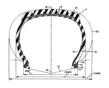
Referring first to Fig. 1, line 10 indicates the
radially outer profile of an H-type rim of size
~ ~ H44.5x16.5-20 as defined b; the Tire and Rim
; Association, Inc. A radial ply aircraft tire 11 of
size H44.5x16.5R20 is shown in cross-section mounted
upon the H-type rim. As used herein and in the
appended claims an "aircraft tire" is understood to
mean a tire of a size designated for use on aircraft by
a tire manufacturer and/or the Tire and Rim
~; Association, Inc.
The radial ply aircraft tire 11 has at least one
35~ carcass ply 12 of reinforcing fabric comprising cords
that are oriented at angles in the range of 90 to 75
::
: .
1 309934
wi~h respect to the mid-circumferential plane M-M of
the tire. It is preferred, but not known to be
essential, that the reinforcing cords in the carcass
ply 12 be comprised of an aramid material. As used
herein and in the appended claims, an "aramid material"
is understood to mean a manufactured fiber in which the
fiber-forming substance is generally recognized as a
long chain synthetic aromatic polyamide in which at
least 85% of thP amide linkages are attached directly
to two aromatic rings. Representative of an aramid
material is a poly(p-phenyleneterephthalamide). The
carcass reinforcing ply, or plies, are anchored around
a pair of substantially inextensible annular beads 13.
While the beads illustrated in Fig. 1 have a
cross-sectional shape that is round, it is understood
that a tire designer could employ beads having any
cross-sectional shape in accordance with good
engineering practices. A bel~ package 1~, comprised of
one or more belt plies of the type known in the tire
art, is disposed radially outwardly of the carcass ply
in the crown portion of the tire. It is preferred, but
not known to be essential, that the reinforcing cords
in the belts be of an aramid material. I~ is believed
that the belts in the belt package may be either
unfolded, folded or a combination of the two at the
discretion of a tire designer. A tread ~ortion 15 is
disposed radially outwardly of the belt package 1~. A
sidewall portion 16 extends radially inwardly from each
lateral edge of the tread portion to a bead portion 17
of the ~ire.
.
A tire according to the invention has a maximum
cross-section width CSWR when it is mounted upon the
designated H-type rim, inflated to its rated inflation
pressure as specified by the tire manufacturer, but not
subjected to any load. The ratio of the axial distance
WBF between the rim flanges of the H-type rim to the
: :
,
1 30q93~
--6--
maximum cross-sectional width CSWR of the tire is in
the range of .7 to .9 (more preferably .75 to .85, and
most preferably .78 to .82) when the tire is mounted
upon said rim and inflated to its specified inflation
pressure as designated by the tire manufacturer, but
not subjected to any load. As used herein, the width
between flanges WBF of an H-type rim, is understood to
be the axial distance between the tangency points of
the bead heel 18 and flange 19 curves of the rim.
Dashed line 20 of Fig. 1 represents the outside
contour of an H44.5x16.5 20 bias ply tire of the type
specified for use with the H-type rim illustrated. The
maximum cross-sectional width of the prior art bias ply
tire is indicated in Fig. 1 as CSWB. It is believed
that if a radial ply tire were to have the same outside
profile as the prior art bias ply tire the radial ply
tire would be unstable because the length of the
reinforcing cords in the-~ire sidewall would be too
great, and the tire would be resting against the rim
flange.
Referring next to Fig. 2, there is shown by way of
example only what is believed to be the desirable
footprint 30 of a radial ply aircraft tire. In the
desirable footprint the footprint width FPW and the
footprint length FPL are such that the ratio of FPW
over FPI. is in the range of .45 to .65, preferably .5
to .6. A tire used in a tire and rim combination
according to the invention not only accommodates the
desired ratio of width between flanges of ~he rim to
cross-sectional width of the tire, but also has a
static footprint such that the ratio of the m~ximum
~ axial width of the footprint to ~he maximum axial
; length of the footprint is in the range of .45 to .65
when the tire and rim combination is subjected to the
rated load for the inflation pressure designated by the
tire manufacturer.
:~:
`':
- 1 3~i9~
-7--
It is customary in the aircraft industry for the
manufacturer of an aircraft to specify the size and
type of tire and rim to be used on an aircraft. If a
tire designer knows from the aircraft manufacturerls
specifications, or the standards issued by the Tire and
Rim associa~ion, Inc., the designer should know certain
design parameters. For example, the maximum outside
diameter of the tire, the diameter of the rim, and the
strength requirements for the tire. A method that a
tire designer may follow in order to define the outside
molded profile of a tire to be used in making a tire
and rim combination according to the invention is
illustrated in Figs. 3-9. In order to use this
procedure a tire designer needs to have:
a. a drawing of the radially outer contour of the rim
that the tire is intended be moun~ed upon;
b ! the dimensions and location of the annular bead
cores;0 c. the maximum outside diameter of the tire in its
infla~ed conditioni and
d. the maximum cross-sectional width of the tire in
its inflated condition.
As used herein the "molded profile" of a tire is the
contour of the interi~f surface of a w lcanizing mold
in which the tire will be vulcanized. It is understood
that a tire designer or a mold designer of ordinary
skill in his profession is proficient at converting the
desired inflated dimensions of a tire to the dimensions
at which the tire should be molded.
The steps of the following design procedure may be
`followed using hand calculators, computers, a
computerized graphics generator (e.g. Computer Aided
Design) to carry out these steps. Preferably, the
drawings used in the following procedure are made full
: :
,
1 309934
scale for the portion of the tire on one side of its
centerplane.
(a) With reference to Fig. 3, draw the bead core 40 in
the correct position (allowing for rubber, plies,
chafers, etc.) with respect to the radially outer
profile 41 of an H-type rim.
(b) Draw a line 42 parallel to the axis of rotation of
the tire and rim combination, spaced at the maximum
molded outside diameter of the tire and draw
another line 43 parallel to the centerplane M-M and
located at the maximum molded width of the outside
surface of the tire.
(c) Locate point A on the centerplane M-M of the tire
located radially inwardly from line 42 a distance
equal to the thickness of the tread rubber and bel~ .
package, tha~ is to say point A is located at the
: 20 top of the radially outermost carcass ply.
(d) Locate point B one-half of the radial distance
between the radially outermost extent of the bead
core 40 and point A and disposed axially inwardlv
from line 43 a distance equal to the desired
thickness of the sidewall rubber (that is to say,
~ the rubber disposed axially outwardly of the
:~ : axially outèrmost carcass ply).
: 30 (e) Locate point C on the centerplane M-M at the same
distance from line 42 as point B (put another way,
ABC is a right triangle).
(f) Measure the distance REL between points A and B,
~: 35 and measure the distance DELY between points A and
C.
: ~ ,
:`'' ,
'
: :
.
_9_ l 30~93~
(g) Generate an ellipse indicated as "INNER ELLIPSE" in
Fig. 4, which is an enlarged view of ~he upper
right-hand portion of Fig. 3 9 by using point C as
the center of the ellipse and point B as a focus of
the ellipse, said ellipse having a major diameter
equal to two times the distance REL between points
A and B, and having a minor diameter equal to two
times the distance DELY between points A and C,
using a rotation of zero.
(h) Generate a second ellipse labelled as "OUTER
ELLIPSE" in Fig. 4, this ellipse having the same
foci as the INNER ELLIPSE, but being offset to be
tangent to line 42 at the centerplane M-M at point
D (point D is located at the centerplane of the
tire at the maximum outside molded diameter of the
tire).
(i) Determine the width of a footprint of the tire
according to the invention, for use on an H-~ype
rim. The first step in determining the footprint
width is to determine the desired area of the
footprint when the tire is mounted upon the
: specified H-type rim, inflated to the
; 25 manufacturer's recommended inflation pressure and
subjected to th~ ra~ed load for that inflation
pressure. The preferable way of determining ~he
footprint area is to measure the footprint area of
the bias ply tire which the radial ply tire is
intended to replace. However, the desired
footprint area may also be es~imated ~using the
equation:
load
footprint area - ~ -
~: 35 inflation pressure
:: ~
-lo-" 1 ~'9"~34
The nex~ step in determining the footprint width is
to solve the following equation for x:
footprint area = 2.2X2
The next step in de~ermining the desired footprint
width is to solve the following equation using the
result of the preceding computation:
footprint wLdth = l.lX
The designer should bear in mind that the ratio of
footprint width to footprint length should be in
the range of .45 to .65.
(j) Draw as shown in Fig. h a line 44 that is parallel
to the centerplane M-M and disposed away from the
centerplane at a dis~ance (1/2FPW) equal to
one-half of the footprint width as determined in
step (i).
(k) Locate point E in Fig. 4 at the in~ersection of the
INNER ELLIPSE and line 44, thPn determine an
equilibrium profile EP as shown in Fig. 5 ~or the
radial ply carcass ~hat the designer wishes to USQ
in ~he tire. The equilibrium profile EP may be
determined any of ~he well known equations for
determining such a profile. Such equations are
published for example in MATHEMATICS UNDERLYING THE
DESIGN OF PNEUMATIC TIRES, by John F. PurdyJ
publis-led by The Goodyear Tire & Rubber Company,
copyrighted 1963. Equations for generating the
equilibrium profile EP are also known from U.S.
; Patent 3,?57,844, the equa~ions from this paten~
35 ~ bPing set forth below for the convenience of a tire
designer.
:
.
,
:~ , '
-
~ 30~q34
cos ~ = R12 - Re2/RS2 - Re2
cos ~ = R22 _ Re2/Rs2 - Re2
R2
and S = J (RS2 - Re2) dR
R
Rl being the radius of the tire at the points where
the carcass reinforcement and the tread reinforcement
meet.
1 being the angle between the carcass
reinforcement and the axis of the tire at the points
where the carcass reinforcement and the tread
reinforcement meet.
; ; Rs being~the maximum radius of the carcass
reinforcement.
;20 Re being the radius of the points of the carcass
farthest from the centerplane of the tire.
R2 being the radius of the tire at the points.where
the carcass reinforcement meets the beads.
2 being the angle between the carcass
~ reinforcement and the axis of the tire at the point
; where the carcass meets the beads.
S being the length of the cords between the points
where the carcass reinforcement meets the tread
reinforcement and~the points where the carcass
30~; reinforccment meets the beads.
If;, for example a~designer chooses to use the
equilibrium equations as ~hey are set forth in U.S.
Pate~t 3,757,844 then:
35~
~,:
: : :
~ ,
-12_ 1 30~934
1. the approximate radius of the portion of the INNER
ELLIPSE between points A and E may be used for the
value of Rl.
2. The distance from the axis of the rota~ion to point
A may be used for Rs.
3. The distance from the axis of rotation to point B
may be used for Re.
4. Other parameters as required for the bead in the
equations may be determined from the drawings.
(1) With reference to Fig. 6, which shows the
equilibrium profile EP, and in which the INNER
ELLIPSE has been deleted, locate point G at the
intersection of the OUTER ELLIPSE and line 44, then
draw a line 45 which is normal to the OUTER ELLIPSE
at point G, and locate point F at the intersection
of the equilibrium profile EP and line 45.
(m) With reference to Fig. 6, strike an arc 46 having
its center located at point F and a radius FG and
extending clockwise from point G towards the
equilibrium profile EP.
(n) As shown in Fig. 7, draw a reference line 47
parallel to the axis of rotation and passing
through point B, then draw a line 48 parallel ~o
the equilibrium profile EP starting at the
~; intersection of reference line 47 and line 43
(maximum molded section width).
(o) As shown in Fig. 8, draw a line 49 which is a
smooth curve blending the arc 46 into line 48 (note
that the portion of the outer profile of the molded
tire which is radially outward of the maximum
cross~sec~ional width is now defined by portions of
the OUTER ELLIPSE the arc 46, line 48, and blending
line 49).
. ~ -
-13- I 30q934
(p) As illustrated by way of example only in Fig. 9,
the portion of the outer surface of the tire
sidewall 50 which is disposed radially inward of
the maximum cross-sectional width of the ~ire may
be determined by a designer in accordance with good
engineering practices. It is important that the
radially innermost portion 51 of the sidewall does
not rest directly upon the rim flange when the tire
is mounted upon an H-type rim and inflated but not
subjected to load.
While a certain method of designing a tire
according to the invention has been shown and
described, it will be apparent to those skilled in the
art that various changes and modifications may be made
in this method in order to design a tire and rim
combination in accordance with the invention.
::
:;
~ .
: ~
' ~ ` ""'
;
. ' ~
.