Note: Descriptions are shown in the official language in which they were submitted.
~-`` 1 3 1 0 0 8 6
STRAIN RELIEF FOR RIBBON CABLE CONNECTOR
This invention relates to high density connectors for
terminating ribbon cable and, in particular, to a ribbon
cable terminating connector housing that cooperates with a
terminating cover to provide strain relief to a ribbon
cable terminated thereto.
U.S. Patent 4,212,507 discloses a strain relief
wherein off-set structure on the connector housing and
terminating cover provide strain relief to conductors
terminated therein. Fluting on the inside cover of such a
prior art device would be ineffective to align the
conductors of a ribbon cable terminated therein to the
insulation displacement contacts as the raised strùcture
along the major edges of the cover would prevent the cable
from engaging fluting on the recessed inner surface of the
cover until after the insulation displacement termination
process has begun. Furthermore, the ribbon cable would be
bending at the time insulation displacement termination
would be starting.
Prior art ribbon cable connectors for terminating
ribbon cable, such as in a daisy chain configuration, are
shown in U.S. Patent Nos. 3,434,093; 4,062,616; 4,068,912;
4,160,574; 4,190,952; 4,410,229; 4,621,885; 4,668,039; and
4,693,533. These connectors typically provide strain
relief such that forces acting on the ribbon cable are not
transmitted to and do not stress the insulation
~.
14446 CA
~ :
, . ,,~ . .. ..
. ~ ~ ~ . . , . '. . '
1 31 0386
displacement electrical connection by clamping the ribbon
cable between a flat or fluted surface on the terminating
cover and the conductor receiving face from which
insulation piercing contacts extend. Typically, the
clamping is achieved within the profile of the mating face
of the connector so as to minimize the width of the
connector.
As ribbon cable conductor centerline spacing is
decreased, ribbon cable becomes more fragile and it
becomes more desirable to provide strain relief at a
location spaced from the insulation displacement
terminations. This is particularly important when it is
recognized that connectors terminated to a ribbon cable
are often unmated from a complementary connector by
pulling on the ribbon cable.
It would be desirable to have a ribbon cable
terminating connector in which the ribbon cable could be
accurately aligned with the conductor receiving slots of
insulation piercing terminals prior to termination thereto
and be provided with strain relief at a distance spaced
from the insulation piercing contacts subsequent to
termination.
In accordance with the invention, an electrical
connector for terminating the multi-conductor cable has a
housing including a cable terminating face, an opposed
mating face and opposed end walls having latch means
14446 CA -2-
-`` 1 31 008~
thereon. The cable terminating face has major edges and
minor edges, with the minor edges contiguous with the end
walls. The major edges extend beyond the profile of the
mating face. The cable terminating face has a rib
extending along the major edges, upstanding from the cable
terminating face. A plurality of contacts are secured in
the housing and have respective conductor receiving
portions extending from the cable terminating face. A
terminating cover defines an inner surface and major side
edges and has latch arms at opposite ends thereof adapted
to engage the latch means on the connector housing to
retain the cover on the housing. The terminating cover
has an off-set recessed from the inner surface along the
major side edges that cooperates with the rib to provide a
space through which a ribbon cable terminated to the
connector passes and to engage the cable to provide strain
relief thereto.
An embodiment of the invention will now be described
by way of example with reference to the accompanying
drawings, in which:
FIGURE 1 is a perspective view of a high density
ribbon cable connector in accordance with the present
invention, with the terminating cover exploded from the
connector housing and with the housing partially cut away;
FIGURE 2 is a side view, partially sectioned, of the
connector of Figure 1, with a ribbon cable positioned to
14446 CA -3-
, . . . .
1 3 1 00~6
be terminated and the termination cover in a
pretermination position;
EIGURE 3 is an end sectional view of the connector in
Figure 2, taken along the lines 3-3;
FIGURE 4 is a side view, partially sectioned, of the
connector of Figure 1, with a ribbon cable terminated
thereto and the termination cover in a terminated
position;
FIGURE 5 is an end sectional view of the connector in
Figure 4, taken along the lines 5-5; and
FIGURE 6 is a top view of the conductor receiving
face of the connector housing.
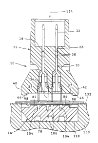
A perspective view of a high density ribbon cable
connector 10 in accordance with the present invention is
shown in Figure 1. Connector 10 may take many forms,
including being shielded or unshielded or being adaptable
for panel mounting. Connector 10 includes housing 12 and
terminating cover 14. Housing 12 has a forward mating
face 16, an opposed conductor receiving face 18, opposing
20 side walls 20,22 and opposing end walls 24,26. Contact
receiving passages 28 extend between mating face 16 and
conductor receiving face 18, with contacts 30 secured
therein.
Contacts 30 are stamped from strip stock, each
contact having a mating portion 32 at one end proximate
the mating face, an insulation displacement plate 34
14446 CA -4-
" 1 3 1 0~86
having conductor receiving slot 36 at the other end that
extend beyond conductor receiving face 18. Securing
means, such as barbs 38 (Figures 3 and 5), are provided
along contact 30 to secure contacts 30 in respective
S passages 28, such as by an interference fit.
In the preferred embodiment, contacts 30 are
positioned in housing 12, with mating portion 32 in two
rows extending substantially between end walls 24 and 26,
with centerlines spaced 0.100 incb (2.7 mm) apart; the
mating portion of adjacent contacts in each row are spaced
0.050 inch (1.85 mm) apart. The insulation displacement
plates 34 form four rows extending substantially between
end walls 24 and 26, with the plates 34 positioned to be
terminated to conductors of a ribbon cable having a
conductor centerline spacing of 0.025 inch (0.925 mm).
Each of four adjacent conductors in a ribbon cable are
terminated. In a respective one of four laterally
ad~acent insulation displacements plates similar to U.S.
Patents 4,668,039 or 4,693,533, in a staggered
relationship, with one of the conductors being terminated
in an insulation displacement plate in each of the four
rows. The invention, however, is not limited to these
contact spacings.
Conductor receiving face 18 has lateral extensions
40,42 that extend laterally beyond the profile of mating
face 16 in that side walls 20 and 22 extend outwardly from
14446 CA -5-
,.. . . .
'
1 31 0086
the axis of the mating portion 32 of contacts 30, as
secured in housing 12. Upstanding from conductor
receiving face 18 on lateral extensions 40,42 and
extending along at least a portion of side walls 20,22 are
strain relief ribs 44,46 defining spaced inner edge
surfaces 47.
End walls 24,26 have terminating cover alignment ribs
48,50 extending therefrom, respectively. Ribs 48,50 may
be chamfered proximate conductor receiving face 18 to
facilitate receiving terminating cover 14 thereover. Rib
48 has guide walls 52 and rib 50 has guide walls 54 which
parallel insulation displacement plates 34. Guide walls
52 and 54 may be spaced differently to provide a
polarization feature such that housing 12 and terminating
cover 14 are polarized relative to each other, and the
terminating cover can only be received on the housing in a
predetermined orientation. Protrusions 56 along guide
walls 52,54 provide an interference fit between ribs 48,50
and terminating cover 14, and absorb any tolerance
buildup.
Latch means are provided on ribs 48,50 to cooperate
with complementary latch means on terminating cover 14 to
secure the terminating cover to housing 12. In the
preferred embodiment, there are at least two outwardly
directed latching protrusions 58,60 displaced along each
of ribs 48,50. Each latching protrusion has a tapered
14446 CA -6-
. .
1 3 1 0086
surface 62 facing conductor receiving face 1~ and a
latching shoulder 64 facing mating face 16. Guards 66
extend outwardly from end walls 24, 26 to prevent
accidental unlatching of terminating cover 14.
Terminating cover 14 is elongate having opposed side
walls 70,72, opposed end walls 74,76, outer surface 78 and
opposed inner surface 80, a portion of which forms fluted
surfaces 82, 84 having the same pitch as a cable adapted to
be terminated to connector 10. Latch arms 86,88 extend to
distal ends 90, 92 and are adapted to cooperate with and
engage latch means on the housing to secure terminating
cover 14 to housing 12. Inner surfaces 80 along side
walls 70,72 have surfaces 94,96 recessed from the general
plane of the central region of surface 80. Recessed
surfaces 94,96 are adapted to be substantially opposed to
ribs 44,46 when cover 14 is secured to housing 12 and
defines spaced outer edge surfaces 98. Outer edge
surfaces 98 are spaced more narrowly than inner edge
surfaces 47 on housing 12.
20 Strain relief ribs 42,44 on housing 12 cooperate with
recessed surface 94,96 on terminating cover 14 to provide
strain relief to a ribbon cable 100 having spaced
conductors 102l when the conductors 102 of cable 100 are
terminated to respective insulation displacement plates
34. The cable 100 covers the ribs, and surface 80 at the
offset and the corners dig into the insulation surrounding
14446 CA -7-
, .. .. .
1 3 1 0086
conductors 102. When terminated, as shown in Figures 4
and 5, cable 100 takes a circuitous path and is clamped in
the space between ribs 44,46 and recessed surfaces 94,96,
as well as spaced inner edge surfaces 47 and spaced outer
edge surfaces 98, with the corners digging into the
insulation to enhance the strain relief. By making the
housing wider in the region of termination, strain relief
is provided at a location spaced from the insulation
displacement terminations of the individual conductors in
respective plates 34.
During termination of ribbon cable 100 onto connector
10, insulation displacement plates 34 pass into recesses
104,106 in inner surface 80. Recesses 104 are continuous
for the outer row of plates 34 while recesses 106 are
discrete for the inner rows of plates. This provides some
plastic adjacent each recess to support the insulation
surrounding the conductor being terminated in a plate
passing into each recess.
Latch arms 86,88 have a channel 108,110 on an inner
20 wall 112,114 thereof that is complementary to respective
terminating cover alignment rib 48,50. Channels 108,110
may be of differing widths to provide a polarizing
feature, as described above. The channels 108,110
cooperate during movement of the termination cover
relative to the housing while initially installing the
termination cover to a pretermination position, but more
14446 CA -8-
... ... . .. .
'
,
1 31 00~6
critically during termination of a cable 100 to connector
10 as the termination cover moves from a pretermination
position to a termination position, to guide the
termination cover parallel to the insulation displacement
plates of the contacts.
Extending across channels 108,110 near distal ends
90,92 is a cross bar 116,118. Each cross bar has a latch
shoulder 120 facing inner surface 80 and a tapered surface
122 facing the distal end. The tapered surface
facilitates cross bars 116,118 riding up over latching
protrusions 58,60. Latch shoulders 120 engage latch -
shoulder 64 protrusion 58 with latch cover 14 in the
pretermination position to accurately position latch cover
14 in the pretermination position, tapered surface 122
also engages tapered surface 62 of latch protrusion 60.
In the terminated position, latch shoulder 120 engages
latch shoulder 64 of latch protrusion 60 to secure
terminating covering 14 to housing 12 and maintain cable
100 clamped therebetween to provide strain relief.
Connector 10 is typically supplied with the
termination cover secured to the housing in the
pretermination position shown in Figure 2 (without a cable
100). Connector 10 is positioned in recess 128 of the
base 130 of a tool, the upper surface 132 of which is
8Ubstantially coplanar with inside surface 80. Upper
surface 132 may be fluted to assist in aligning conductors
14446 CA -9-
,
1 31 0086
102 with slots 36 in plates 34. The edge of cable 100
also extends along edge 136 of inner surface 80 to assist
aligning conductors 102 opposite respective slots in
insulation displacement plates 34. In this manner,
5 skewing of the cable due to decreased width of the
connector is minimized. To position connector lo on cable
100, cable 100 is slid into and through the space between
plates 34 and inside surface 80, with cable 100 engaging
fluted surfaces 82,84 to position conductors 102 opposite
slots 36 for termination. Cable 102 may be clamped (not
shown) against surface 132 to maintain the relative
positions so achieved. Housing 12 is moved in the
direction of arrow 134, such as by a press (not shown) to
cause conductors 102 to terminate to plates 34 in a known
lS manner and to cause terminating cover 14 to move from a
pretermination position to a termination position with
respect to latch protrusions 58,60. In the terminated
position, latch arms retain termination cover 14 in the
latched po8ition which retain8 cable 100 in the circuitous
con~iguration which provides strain relief.
14446 CA -10-
. ~ .
,' :
. ~ , .