Note: Descriptions are shown in the official language in which they were submitted.
1 31 0~6
1 BACKGROUND OF THE INVENTION:
2 1. Field of the_Invention:
4 The present invention relates to multi-color
offsek printing presses, for variable formats, intended
6 for printing on continuous webs from rollers or fan-
7 folded sheets and perforated such as 'Caroll' types.
9 2. Descr1ption of the Prior Art:
11 At the present, continuous printing is carried out
12 on very large printing units which are well adapted
13 with high rates for heavy runs. However, the setting
14 up is long and out of proportion for short or medium
run~. As well as this, the rapid development of micro-
16 computing and falling production costs mean that many
17 medium sized companies are becom1ng computerized. This
18 has created a new demand for short and medium runs of
19 continuous printing. Traditional printers, equipped
mainly with sheet-fed presses, cannot respond.
21
22 Producers of offset presses, aware of this new
23 market, are beginning to produce, in relatively small
24 numbers, equipment which is more appropriate to this
demand. However, their lack o~ versatility adde~ to
.
.
- 2 -
1310226
1 the fact that their prices, compared to similar sheet-
2 fed equipment, are about three times as much, make it
3 difficult to absorb their cost at the present stage of
4 development of this new procedure. On top of this,
these presses are unly designed for the printing of
6 forms or labels for computer use. These presses cannot
7 dsal with continuous web printing where there are no
8 ~Carollf perforations. Their traction systems for the
9 web and their margin guide are related to the holes of
these perforations.
11
12 Now in the field of printing from an unperforated
13 web for short or medium runs, such as labels for
14 example, there exists a massive market which is totally
beyond the reach of the traditional printer who only
16 has sheet-fed offset presses.
17
18 As well as this, these small presses may have only
19 a mono-color passage through the machine. Sometimes
they are able to deal with only one color at each
21 passage through the machine. They may also be equipped
~2 with a complementary inking head allowing for an extra
23 color during the same passage. This extra color, which
24 is obtained on the same blanket as that which equips
the main printing unit of the press, does not guarantee
- 3 -
1 31 0~26
1 a superimposition of colors. There i5 a risk of the
2 inks running together after a short run, even by using
3 inks of a different vi~cosity and taklny all sorts of
4 precautions.
6 For a professional printer, these complementary
7 inking heads leavs their particular color on a single
8 blanket which is inked with another color by the inking
9 unit of the press~ They are ~ery useful for printing
which does not require a perfect juxtaposition of
11 colors. It happens that at the moment the majority of
12 continuous printing requires at least two or three
13 colors of which some are superimposed. This
14 necessitates the use of a blanket per color to be sure
of obtaining, without problems, a perfect job.
~6
17 These problems ara the same for continuous
18 printers who don't have either one or several color
19 presses enabling them to change the format, at will and
in a few minutes, depending on the different types of
21 successive printing materials to be dealt ! with.
22 Professional continuous printers at present are
23 equipped with multi-color presses where each printing
24 unit has its own printing blanket, thus avoidin~ the
risk of different colored inks running together. The
.
- 4 -
1 3 1 0226
1 rates of these presses are in the order of 30,000 to
2 50,000 copies per hour.
4 A prior art press is shown in Figure 1. A roll of
paper feeds the press 2 with a web of paper 3 which
6 goes successively through an automatic lateral guiding
7 device 4, then between the blanket bearing cylinders 5
8 and the pressure cylinders 6 of the different printing
9 units 7. Havlng been printed, the paper web 3 is then
drawn by a rotary press 8 and rerolled with the help of
11 the roll holder 9 or treated with the help of
12 established devices. These devices are adaptable
13 depending on their use and enable, for example,
14 'Caroll~ type perforations to be obtained, then
longitudinal and transversal perforations and then fan-
I6 folding. Depending on the presses and the end product,
17 cutting devices are attached at the exit of the press
18 to change the web ~nto sheets~ These machines are very
19 efficient for long runs but in the case of short or
medium runs ~of the order of 1000 to 20,000 copes)
21 which succeed each other with variable formats, they
22 are inadequate. They require too much precise setting
23 time, usually requiring several hours in the case of a
24 change of format. They have only a limited number o~
formats.
- 5 -
1 31 ~22~
2 This comes mainly from their operating principle.
3 In effect, these presses work continuously without
4 stopping between each printing cycle. The
circumference of the blanket-bearing printing cylinders
6 5, the pressura cylinders 6 and the plate-bearing
7 cylinders lo determine the duration of the pxintin~ and
8 therefore the format~ This means that for each change
9 of printed material which isn't of the same format or
could be divlded from it, it is necessary to change the
11 cylinders and the sets of gears controlling them. The
12 printer is obliged to possess and change on each press
13 a certain number of cylinders ~of variable diameters.
14 In any case because of this requirement, the printer is
very limited by the formats of the printed materials he
16 can offer to his clients.
17
18 The designers of continuous printing presses,
19 aware of this problem, tend to propose to the users
continuous presses with variable formats. In the prior
21 art type of Figure 1, the printing units 7 are
22 interchangeable, which saves some of the time. Thsre
23 nevertheless is still too much time required between
24 each setting occasioned by a change of format. This
solution is costly and limiting for the printer. This
-- 6 --
1 31 0226
1 solution ls reflected in the price of the printed
2 material and is only a palliative which seriously
3 limits the number of possible formats.
. 4
Recently a three-color continuous press, with a
6 variable format, and only dealing with 'Caroll' fan-
7 folded form webs, has brought the beginning of a
8 solution to this problem. However, it has, amongst
9 others, two serlous drawbacks. The three colors are
obtained from a single blanket. It has only been
11 designed to deal with forms from 'Caroll' webs. As
12 well as this, the basic design means that it is not
13 possible to build units which can be distributed widely
14 at a low price.
.
.
:
: - 7 -
1 31 0226
1 SUMMARY OF THE INVENTION
3 This inv~ntion takes into account the inadequacies
4 of techniques at the present time. It allows for a
range o~ multi-color and multi-purpose offset presses,
6 largely variable in format, to be dealt with by
7 changing movable feed and reception modules withln only
8 a few minutes. It enables both printed material on
9 rolls or in ~ Caroll' webs.
11 In one form of the invention the presses have a
12 printing and general operating mode which is similar to
13 that of the one or several color 'continuous t type
14 offset presses. They also use for superimposing the
colorsj one blanket per coLor. Like the continuous
16 presses and depending on their use, the presses based
17 on the invention may or may not keep the same basic
1~ functions to which tho~e brought by the invention are
19 added.
21 The mode of feeding from a roll a5 well as the
22 devices for guiding and lateral positioning of the web
23 are practically the same. They can also use all the
24 accessories generally used with this type of press such
as, for example, those used for ~Caroll' fan-folding
.
- 8 -
1 3 1 0226
- 1 from the printed web or cutt~ng devices. The printing
2 units can be the same, enabling for example,
3 simultaneous recto-verso 'blanket against blanket'.
In another form of the invention, the presses have
6 a printing and general operating mode which is similar
7 to the multi~color offset presses oE 'sheet by sheet'
8 type. They can al50, as in the first form of the
9 invention, depending on their use, if required, keep
their basic functions to which are added those bxought
11 by the inventlon.
12
13 In the invention, the pressure ex~rted between the
14 blanket bearing and pressure cylinders, and the paper
web driving device is released and reapplied during ~he
16 printing cycle, in order to obtain printed material of
17 any format within the printing limits of the press.
18 This releasing and applying of pressure is adjustable
19 over the 360 degrees of the cylinders' ircumference.
The web of paper is repositioned during the time when
21 the pressure is released before the subsequent
~2 printing. Guiding devices position the web laterally.
23 The same guiding devices and rotary presses work in
24 combination with each other for controlling the
release and application of pressure. An electronic
1 3 1 0226
1 device ensures, depending on the format, the register
2 of the web, with or without ICaroll' perforations.
4 In a preferred mode of the invention and in its
fixst form for 'continuous' type presses, the print}ng
6 is obtained one printing cycle out o~ two. The
7 pressure is released at the end of the format after
B printing. The paper web is not taken up because of the
~ release of pressure. The paper web is repositioned.
~ighter printing units can be used which are therefore
11 much less costIy. In this set-up the plate bearing
12 cylinder is inked twice on each printing.
13
14 Based on this conception and depending on the
di}ferent possible ~ersions with the aim of lower
16 production costs, the printing unit may pxeferably be
17 built from a basic set~up which enables al} or part of
18 the elements necessary for the different versions to be
19 incorporated. This printing unit is made up of a small
movable unit which adds an extra color on a single
21 blanket. ~ This small complementary unit also has the
22 advantage for each printing cycle of ~having two inking
23 cycles. ~eGause of this, it can be much lighter in
24 comparison to a normal unit.
~ .
-- 10 --
131~27~
1 These presses can, for bigger runs and with the
2 same elements, work purely in the continuou6 mode. In
3 this case they are equipped with p:rintiny units for
4 which the diameter of the printing cylinders
corresponds to that of the format being dealt with or
6 one which can be di~ided from the latter.
8 These presses can also deal with printed material
9 in 'alternative continuous'. This printing is mainly
used with 'Caroll' continuous web forms and enables a
11 form to be printed, then a given number which are not
12 printed. T~e forms which are not printed are printed
13 with different printed material ~rom the others, in
14 their turn, in successive passages through the machine.
16: In the second form of the invention, the result
17 obtained is broadly the same as far as continuous
18 multi-colored printing with largely variable formats is
19 concerned. However, the presses cannot because of
their design, which uses a cylinder 'gap', print purely
21 in the continuous mode. On the other hand they can be
22 usefully sheet-fed or fed by continuous web for rolls
23 or from 'fan~folded' with 'caroll' holes.
24
,
1 3 1 o~6
1 The different feed and reception modules of these
2 sheet-fed or continuous presses are preferably movable
3 and interchangeable with those used on continuous
4 presses. A11 the means employed for producing the
invention can also be used with existing presses to
6 render them multi-purpose.
8 Without going beyond the framework of the present
9 invention, mono-color presses of the continuous or
'sheet' type can be linked mechanically and use all the
11 means which are the features o~ the invention. Purely
12 as an example and with reference to the attached
13 drawings, a variety of set-ups and possibilities
14 offered by the presses are described for the purpose of
illustrating the invention.
16
17 BRIEF DESCRIPTION OF T~E DRAWINGS
18 Figure 1 is a schematic sectional view of a prior
... :
19 art printing pres~.
21 Figure 2 is a schematic sectional view of a press
Z2 constructed in accordance with this invention and
23 capahle of operating purely continuously or
24 continuously with varying formats.
- 12 -
1 31 0226
1 Figure 3 is a schematic ~ectional view of the
2 press of Figure 2, shown working continuously with
3 mainly ~ariable formats.
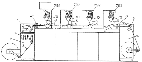
Figure 4 represents schematlcally a press made up
6 of two printing units 7Dl and 7D2/ Figure 9, fitted
7 with a small unit for an extra color 7E for continuous
8 working with mainly variable formats.
.
lo Figure 5 represents schematically a 'continuous'
11 press for mainly varlable formats, made up of two
12 printing units 7Dl and 7D2, Figure 9, equipped with
13 supply 13 and reception 14 modules to deal w1th
14 'Caroll~ perforated webs.
16 Figures 6, 7, 8 and 9 represent schematically, in
17 their different version, the printing unit which equips
18 continuous presses.
19
Figure 10 represents schematically a conventional
21 four color sheet-fed press, equipped with a sheet feed
22 15 and reception 16.
23
24 Figure 11 represents schematically the sheet-fed
press of Figure 10 equipped with two supply 11 and
- 13 -
~ 3 1 ~2~6
1 reception 12 modules enabling continuous printed
2 material variable ln format to be dealt with from paper
: 3 webs 3 of f the roll 1.
Figure 12 represents schematically the sheet-fed
6 press of Figure 10 equipped with two supply 13 and
7 reception 14 modules enabling continuous printed
8 material with variable formats from 'Caroll' perforated
9 webs to be dealt with.
11 Figures 13-18 ~how an example of a continuous
12 pr1nting press with variable formats.
13
- 14 -
1~1022~
1 Deta1led Description of the Invention
3 Elements in the drawings which are in common with
4 the prior art press of Figure 1 are indicated with the
same numerals and may not always be discussed.
6 Referring to Figure 2, the press is equipped with an
7 intexchangeable supply module and a guiding device 4
8 and a reception device 12. It is made up of printing
9 units 7Bl and 7B2, which are shown more in detail in
Figurs 7. These units enable purely ! continuous'
11 printing to be carried out. In continuous printing,
12 there is one inking of the printing plate for each
13 printing cycle. Variable formats may be used by
14 substituting units 7Cl and 7C2, Figure 8, or units
7Dl and 7D2, Figure 9.
16
17 Figuxe 3 represents schematically this same press
18 working only 'continuously' with mainly variable
19 formats. There will be one printing for two inking
cycles of the printing plate. The press of Figure 3 is
21 fitted with supply 13 and reception 14 modules designed
22 for dealing with material printed from iCarolll webs.
23 It is made up of printing units 7Cl and 7C2 which are
24 shown in more detail in Figure 8. Units 7Cl and 7C2
are lightened. The crushlng cylinders, the
~6 distribution and ink form roIlers, all shown in black
- 15 -
1 31 0~26
1 in Figures 6 and 7, have not been fitted. This
2 printing unit inks the plate 10 twice per printing and
3 gives an excellent inklng quality.
Figure 4 represents schematically a press made up
6 of two printing units 7Dl and 7D2, Figure 9, fitted
7 with a small unit for an extra color 7E for continuous
8 working with mainly variable formats. The press of
g Figure 4 has a small unit 7E ~Figure 9) for extra
color. The press can also be equipped with the
11 printing units 7Al and 7A2, Figure 6, or 7Bl and 7B2,
12 Figure 7, for use also in pure 'continuous' printing.
13 The supply 11 and reception modules 12 complete this
14 assembly.
16 Figure 5 represents schematically a 'continuousl
17 press for mainly variable formats, made up of two
18 prlnting units 7Dl and 7D2, Figure 9, equipped with
19 supply 13 and reception 14 modules to deal with
'Caroll' perforated webs. Figures 6, 7, 8 and 9
21 represent schematically, in their different versions,
22 the printing unit which equips these 'continuous'
23 presses.
24
- 16 -
1 31 02~G
1 Figure lo represents schematically a conventional
2 four color sheet-fed press, equipped with a sheet f0ed
3 15 and reception 16. It shuuld be noted that all ,the
4 blanket-bearing 5, pressure 6, and plate beaxing 10
cylinders are of a larger dlameter (about 180
6 millimeters instead of 120 millimet:ers) than that of
7 the cont~nuous presses of Figure 1. Also, these
8 cylinders incorporate 'gaps' called cylinder 'gaps' to
9 enable the pressure cylinders 6 to be fitted with pick-
up yrippers for the sheet which is to be printed. In
11 this version of the invention,~ the web is positioned,
1~ drawn through and guided with the help of the same
13 means as those described ~n detail below concerning the
14 'continuous' type presses. The pressure of the blanket
bearing cylinder 5 is also released at the end of the
16 format.
17
18 Figure 11 represents schematically the sheet-fed
19 press of Figure 10 equipped with two supply 11 and
reception 12 modules enabling continuous printed
21 material variable in format to be dealt with from~paper
22 webs 3 off the roll 1. A tension buckle 20 enables the
23 register and the format to be adjusted between each
24 printing unit. A remargin drum 1~ draws the web 3
- 17 -
1 backwards between sach printing cycle. A detector 17
2 gives a signal to the electronic control.
4 Figure 12 represents schematically the sheet-fed
press of Figure lo equipped with two supply 13 and
6 reception 14 modules enabling continuous printed
7 material with variable formats ~rom 'Caroll' perforated
8 webs to be dealt with. All the s~me ~lements such as
9 the remargin drum 18, the pin tractors 19, the tension
buckle 20, the feed modules 13 and 11, and reception
11 module 14 and 12, equip this press in the same manner
12 as those of the 'continuous' type.
13
14 It is obvious that numerous combinations are
possible. For examplej the version illustrated in
16 Figure 3, in relation to a continuous press with
17 variable formats, can be slightly modified to deal as
18 well with this same printed material in a purely
19 continuous manner by using broadly the same means as
those indlcated in Figure 2.
21
22 Figures 13-18 show an example of a continuous
23 printing press with variable formats. This press is
24 made up of ~an assembly of printing modules 2~ and 2B
which are additional depending on the number of inking
1 3 1 ~226
1 heads which are necessary. The association of the
2 supply module 13 and the reception module 14 enable the
3 fan-folded web 3A with I Caroll ~ perforations to be
4 dealt with. A rapid change by the supply module 11,
Figure 14, and receptlon ~odule 12 easily transforms
6 the press and enables the web 3 which arrives on a roll
7 to be dealt with. The printing units 7Cl and 7CZ,
8 Figure 13, have adjustable positions on their modules
9 so that the length of web to be printed between each
pressure cylinder 6 corresponds to a whole number of
11 formats so as to obtain the register.
12
13 A preferred means for the printing modules 2A is
14 shown in Figures 15, 16 and 17. A frame 21, Figure 16,
is made either by mechanical welding, or in a smelting
16 works either from casting steel or casting aluminum.
17 Brackets 21B incorporate devices for positioning on the
18 ground which are adjustable in height so that the
19 levelling of the machine can be obtained correctly.
21 Threaded feet 22 which screw or unscrew depending
22 on the helght required are held firmly in place by
23 fixation rods 23 together with washers 24 and nuts 25.
24 Supports 26 on which the stanchions z7 are fixed and
blocked by the nuts 2& are held in the angles of the
-- 19 --
13102~6
1 frame 21 and spacers 21A. The stanchions 27 are screwed
2 into guiding bars 29 on which slide split rings 30
3 mounted on the bearings 31 for supporting flanges 32 of
4 the printing module. The flanges 32 in which th~ plate
bearing cylinder 10 and th2 pressur~ cylinder 6 rotate
6 are assembled by a set of spacers, of which only the
7 spacer 33 is shown for easy understanding of the
8 drawing.
A crossing shaft 34 turns in the rings 35 set in
11 the bosses 31A on two of the bearings 31. A set of
12 gears 36 and a crank wheel 37 are keyed on this shaft
13 34. The movement of the crank wheel 37 causes the
14 rotation of the gears 36. The gears 37 engage racks
38 fixed on the frame 21, to ensure the movement and
16 the ~ositloning of the whole of the printing module. A
17 plate bearing cylinder 10 and a pressure cylinder 6
18 rotate in tha fixed bearlngs 10A and 6A. On the other
19 hand the blanket bearing cylinder 5 is pivotable by
means of its connection to one end of connecting rods
21 39, Figure 17. Each connecting rod 39 has a slide 39A,
22 Figure 15, bearing against adjustable eccentrics in cam
23 40.
24
- 20 -
1 3 1 ~26
1 At the other end of the connecting rods 39, Figure
2 17, axles 41 are forced together, pivoting at one of
3 the ends of the elbow levers 42 articulated on the
4 fixed axles 43.
6 At the other end o~ the elbow levers 42, single
7 movement hydraulic cylinders 43A are linked. The head
~ of the piston rod, which rotates on the axles 44 and
9 the body of the hydraulic cylind~rs 43A on the fixed
axles 45. The cylinders 43A, being single movemsnt
11 ones, return after the releasing of the pressure on the
12 hydraulic circuit is ensured by springs 46.
13
14 The control o~ the cylinders 43A is carried out by
a ronventional hydraulic source 47, Figure 13, which is
16 mhde up of a pump, an accumulator, a pressure
17 controller, rate controllers, distri~ution electro-
18 valves and all the means necessary. For the sake o~
19 clarity only the complete unit is shown in the drawing.
21 The monitoring of this hydraulic source 47 is done
2~ from an electronics eguipment ~cabinet 48 linked to a
23 ccntrol panel 49 on which are centralised all the
24 adjustment controls which are vital for the correct
operating of the printing press. This includes
- 21 -
131~2~6
1 selection of format, printing rate, operating of the
2 dampening and inking units, pressurizing of the blanket
3 bearing cylinder, setting in motion of the printing web
4 and tha printing mode selector.
6 The hydraulic action caused by the cylinders 43A,
7 Figure 15, linked to the levers 42, connecting rods 39
8 and eccentrics 40, causes the blanket bearing cylinder
9 5 to approach the plate bearing cylinder 10 and the
pressure cylinder 6. The plate bearing cylinder 10 and
11 the blanket bearing cylinder 5 have tracks lOB and 5B,
12 Figure 17, commonly called Icardons', which ensure a
13 functioning which is very precise and flxed between
14 their axes during the printing cycles. In contrast the
distancs between the axes of blanket bearing cylinders
5, Figure 15, and the pressure cylinder 6, is obtained
17 due to the juxtaposed actions of the slides 39A, the
}8 levers 39 and the adjustable eccentrics 40.
lg
The action of the eccentrics 40, for which the
21 traditional means of adjusting have not bsen shown for
~2 easier understanding of the drawing, brings ~orward or
23 separates the blanket bearing cylinder 5 from the
24 pressure bearing cylinder 6 due to the thrust of the
cylinders 43A. The required variable distance between
~ 22 -
1 3 1 0~26
1 the axes is thus obtained d~pending on the thickness of
2 the web to be printed and the pressure to be exerted to
3 obtain a good transfer of the ink placed on the
4 blanket, without there being a shortfall or an excess.
6 Each printing cylinder has a gear which ensures
7 its rotations. A gear lOC, Figure 16, of the plate
8 bearing cylinder 10 engages with a gear 5C of the
9 blanket bearing cylinder 5. The gear 5C engages with a
gear 6C of the pressure cylinder 6. The gear 6C
11 engages with the cylindrical section of a double gear
12 50 turning on a fixed shaft 51 fixed on a flange 32 of
13 the mobile printing unit. The conical section o~ the
14 double gear 50 is drawn into rotation by a conical
gear 52 turning in a bearing 53/ Figure 16, fixed on a
16 cross-bar 33. The hub o~ the conical gear 52 has a
17 grooved bore in which a :grooved shaft 54 is set in
18 motion by a moto-reducing unit 55, Figure 13, which
19 immobilizes it txansversely. In this manner each
printing unit is carried along, no matter what its
21 position on the guiding bars 29, Figure 15.
22
23 ~ ~ The moto-reducer unit 55, Figure 13, the hydraulic
24 source 47, and the control panel 49 are incorporated in
the basic module 2A. The remargin drum 1~ is driven in
.
- 23 -
'
~ 3 ~ ~226
1 the opposite direction to the movement of the web 3A by
2 a year 6C of the pressure cylinder 6 vi~ a gear 56,
3 serrated pulleys 57 and 58 and a serrated b~lt 59. The
4 pre sure rollers 60 slightly pinch the web 3A by means
of levers 61 articulated on an axle 62 and by a
6 pressure spring 63.
8 Rollers 64/ tuxning at the extremities of the
9 lever 65 rotating around the axle 66, enable precise
adjustment of the register to be made by moving a
11 micrometric adjusting screw 67. Screw 67 varies the
12 position o~ the web 3A in relation to the pressure
13 cylinders 6. This movement of the web 3A is local and
14 only effects the two rol~ers 64 without causing any
modlfication of the register of the other succeeding
16 printing units.
17
18 Only the printing unit 7Cl of the base module has
19 in the different versions of the invention~, a
remargining drum 18 which is used for restretchinq the
21 'Caroll' web whether perforated or not. The other
22 printing units are equipped with pin tractors 19 whlch
23 can drive a paper web perforated with 'Caroll' holes.
24 A stepping motor 68 monitored by an electronlcs
~5 equipment cabinet 48j ensures the rotation of the
- 24 - -
~ 31 022~
1 rotary presses 19 by means of serrated pulleys 69 and
2 70 and a serrated belt 71.
4 The description which follows explains the
funationing of the whole press, Figuxe 13, equipped
6 with modules 13 and 14 which enable continuous fan-
7 folded printing from a web perforated with 'Caroll'
8 holes, to be ~arried out. The supply module 13 picks
g up the perforated web 3A from the packet lA placed on
the plate 13A. The extension bars 13B slightly stretch
11 the web 3A which goes over the slide 13C and the
12 guiding slides 13D into tha printing modules 7Cl. on
13 ooming out of the last prlnting unit 7C2, the web 3A is
14 directed towards the pin tractors 14D of the slide 14C.
The step motor 14E ensures the rotation of the pin
I6 tractors 14D by the se~rated pulley and belt unit. The
17 web 3A is printed and pushed bekween the lateral
18 guiding bars 14F, onto the ~tack 9A of folded paper.
19 The web 3A is positioned on the movable plate 14B, the
vertical movement of which is controlled in its
21 downward movement by the level detector 14G. Level
22 detector 14G keeps the top ~f the pile 9A at a constant
23 distance from the ~guiding bars 14F, thus ensuring a
24 regular folding of the web 3A.
~:
~:
: - 25 -
1 3 1 ~226
1 Once this web is in place, it is essential to
2 position it depending on the fold and in relation to
3 the printing cylinder 6 of the first printing unit 7Cl,
4 50 as to adjust the register of tllis first printing.
This functlon is obtained simply by moving the web by
6 acting on the simultaneous manual control o~ the step
7 motors 68 and 14E of the pin tractors 19 and 14D which
8 are situated on the control panel 49. The movement of
g the printing unit 7C2 on the guiding bars 29 adjusts
the positioning of the fold for the printing by
11 reference of the second color. It should be remembered
12 that there must be a whole number o~ formats between
13 the two printing units. A slight correction in the
14 register of a unit ls obtained by a slight tilting of
the levers 65 activated by the adjustment screw 67
16 without an effect on the margin of the other printiny
17 units. Thls precise adjustment of the margin on each
18 unit is carried out while the machine is working during
19 the printing.
21 once the web is in its place, correctly stretched
22 and positioned, i~ is necessary to display on the
23 control panel 49 the Yalue of the variables
24 corresponding to the work to be carried out. ~his
control panel 49 is linked to the electronics equipment
- 26 -
1 31 02~6
1 cabinet 48 o~ established desiyn, the different actions
2 of which are described further below so that a good
3 understanding of the operating of the printing press is
4 possible.
6 ~y activating the start butto:n 49A, Figure 18,
7 controlling the overall electric system, the whole of
8 the machine is activated and in particular the control
9 panel 49, Figure 13, the electrical and electronic
equipment cabinet 48, the hydraulic source 47, and the
11 reception module 14 which controls the reduction of the
12 stack 9A~ Pressure on a 'Cylinders' button 49B, Figure
13 1~, activates the moto-reducing unit 55, Figure 13,
14 which sets of~ the rotation of all the cylinders of the
printing press so as to allow, as a first stagej the
16 preparation of the dampening and inking units, as in
17 all conventional offset printing presses, A
18 'dampenlng' button 40C, Figure 18, having been pushed,
19 the clamp form rollers come down onto the plate of the
plate bearing cylinder 10, Figure 13. The ink form
21 rollers do the same if the 'inking' button 49D, Figure
2Z 18, is in turn pushed. Renewed pressure on these same
23 buttons cancels the previous requested action.
24
1 3 1 0226
1 The display of the format for printing in inches
2 on electronic displays 49P is obtalned by pushing
3 buttons 49E. The dlsplay in fractions of inches,
4 sixths or eighths is obtained on the displays 4sN by
pressure on the buttons 49F. The :number of prlnts to
6 be obtained i~ programmed with the help of the buttons
7 49G and appears on displays 49M. On each printing, a
8 unit will be eliminated and the return to zero will
9 stop the machine at the end of the run required.
Pressure on one of the 'margin' buttons 49H mov~s the
ll web for printing in the direction requlred, rapidly if
12 the pressure i9 maintained, step by step if the button
13 is depressed with short impulses, so as to correctly
14 position the print to obtaln its register, as explained
previously. The machine being ready to print (inkiny,
16 dampening, perforated web in position), the format
17 displayed as well as the length of the run to be
18 carried out, pressure on the 'Impressionl button 49I
l9 will set off the printing cycles.
21 The grooved shaft 54, Figure 13, which drives all
22 the press' cylinders, allows it, due to the ratio of
23 the gears used, to turn at the same speed as that of
24 the pressure 6, blanket bearing 5 and plate bearing 10
cylinders. The serrated pulley 72, wedged on the
-- 28 -
1310226
1 grooved shaft 54, drives at the same speed an impulse
2 generator 75 via the serrated pulley 73 and the
3 serrated belt 74. This impulse generator 75 has two
4 tracks. The first track monitors the step motors which
drive the pin tractors by pulling on the web at the
6 same linear speed as the circumferential speed oE the
7 printing cylinders. The second track only generates a
8 single impulse per rotation, which is used to set off
: 9 the step motors of the web pin tractors and to activate
the hydraulic cylinders 43A, Figure 15. This moves the
11 blanket bearing cyllnder 5 by bringing it to its
12 printing position, bearing against the eccentrics 40
13 and 'cordon against cordon' with the plate bearing
14 cylinder 10.
16 The release of pressure at the end of the printing
17 cycle and the stopping of the step motors of the web
18 pin tractors are controlled by :the calculator of the
19 electronics equipment cabinet 48, Figure 13, when the
'format' counters return to zero. Obviously the
21 initial impulse, produced on each rotation by the
22 impulss generator 75, i~ generated at a very precise
23 position in the printlng cycle, in ~uch a way as for
24 there to be a simultaneity between the departure of the
web, the putting under pressure and driving by the
: - 29 ~
1 3 1 ~226
l action of the blanket bearing cy~ der 5 against the
2 pressure cylinder 6. It 6hould be noted that the
3 action of the margin drum 18 turning :Ln the opposite
4 direction to the passage of the web stretches the
latter permanently without excessive constraint due to
6 the juxtaposed action of the pressure rollers 60 and
7 the sprlngs 63.
9 The electronic signal of the 'Start', controlling
the starting of the step motors and pin tractors 19 and
11 14D, is adjusted in such a way that the web is drawn
12 forward about half an inch be~ore it is drawn along at
13 the same speed by the printlng cylinders. This ensures
14 that the response times, which are different depending
on the means used in combination (hydraulic, mechanical
16 and electronic~, do not cause a lack of precision,
17 dragging on ~he holes or untimely breaks in the web.
18 This manner of proceedlng neutratize~ the inertia of
l9 the band when the pin tractors l9 and 14D start and
enables lt to reach its real speed before being pinched
21 and drawn along by the pressure cyllnders. This
22 ensures considerable repe~ition of the printing
21 register from one printing to the other and therefore a
24 constant register from color to color throughout the
run.
- 30 -
1 3 1 O ~
2 In order to obtain a full format printing of the
3 printed material and taking into account the response
4 time of th~ devices for releasing the pressure of the
~ printing cylinders, as 600n as the traction o~` the web
6 is ~reed by the press, the pin tractors lg and 14D are
7 immediately driven backwards about an inch. This moves
8 back and positions the web 3A before the following
9 printing cycls. To do this, the electronic calculator
has been programmed to control on the base of a
11 displayed ~ormat a forward and backward fractlon of an
12 inch. This fractional value of an inch is not absolute
13 and has been determined experimentally. In fact,
14 irrespective of the rate of operating of the press, the
release of the pressure is obtained in less than half
16 an inch. The margin drum 18 accompanies the web 3A and
17 moves it backwards, keeping it stretched before the
18 beginning of the following printing cycle. Considering
19 the example of a printing format of 12 inches, the
press may be readied to print as follows:
21
22 a) display of 12 inches on the control panel 4G;
23
24 b) pressure on the button 'Cylinders' 49B which
sets in motion all the functions of the press;
26
- 31 -
2~
1 c~ pressure on the button 'Print' 49I which
2 permits the printing cycle;
4 d) 'Startl impulse of the impulse generator 75,
Figure 11.
7 This starts the beginning of the traction of the
8 web 3A with the help of the pin tractors 19 and 14D,
9 the total movement of which will be of twelve plus one
inches, that is 13 inches. This starts simultaneously
11 the beginning of the movement of the hydraulic
12 cylinders 43A, Figure 17. This results in the putting
13 under effective pressure of the printing cylinders.
14 Their slight difference in startlng time having allowed
the web 3A to piak up its speed by covering about half
16 an inch of its total movement. The effect~ve printing
17 will be on a length of twelve inches. At the end of
18: twelve inches, the format signal ends, which sets in
19 motion the release of pressure of the ~ylinders.
During the release from pressure, the web moves forward
21 a maximum of a supplementary half inch. The web 3A,
22 Fi~ure 13, stops. The web 3A moves backwards an lnch
23 by the simple movement of the pin tractors 19 and 14D.
24 The web stops, is positioned and stretched by the
margin drum 18 while waiting for the next 'start' of
;
- 32 -
t ~ 1 Q2~6
1 the impulse generator 75. ~he next 'start' sets the
2 following printing cycle in motion.
4 Figure 14 represents the same printing press with
variable format in a set-up for continuous printing
6 from reel to reelO The supply module 11 brings the web
7 3 rolled on the reel 1, the drlvin~ of which ls ensured
8 by a moto-reducer, not shown here for the clearness of
9 the drawing. The rotation speed is controlled by the
control belt and obtained with the roller lA supported
11 by the levers lB. The roller lC has flanges lD with an
12 adjustable opening depending on the width of the web 3,
13 ensuring pre-alignment before it rolls on to the
14 stretching rollers lF.
16 Then the web 3 goes into the guiding module 4, the
17 roller 4A of which belng oriented hori~onta}ly is
18 linked by the visual detector of the edge of the web 4B
19 and the usual associated means of control, not shown
here as they are well-known. At the exit of the last
21 printing unit 7C~, via the remargining drum 18 and its
22 pressure rollers 60, the margin rollers 64 positioned
23 by the adjustment screw 67, the printe~ web passes in
24 the line reader or detector 17 before going into the
winding module 12. The web 3 passes over the traction
- 33 -
1 31 Q~2~
1 cylinder 12A driven by the step motor 12B, the serrated
2 pulleys and belt 12C, 12D and 12E. The electronic
3 equipment cabinet 48 and the control panel 4~ control
4 this unit, monitored by the impulse generator 75. The
pressure rollers ~, flxed at one extremity of the
6 levers 8A pivoting on the bearing~ 8B by means of the
7 shaft 8C, press very strongly on the web 3 due to the
8 action of the tightening screw 8D, thus ensuring
9 excellent drive.
11 The printed web 3 treated in this way is wound on
12 the reel 9, which is set in motion by a moto-reducer
13 not shown for the clarity of the drawiny but the action
}4 of which is known in continuous printing from reel to
reel. The rotation speed ls controlled by the belt
16 roller 12F equipped with flanges 12G turning on one of
17 the ends of the levers 12H. As in the example
18 explained pre~iously and illustrated by Figure 14, the
19 web 3 is put in place and the press is prepared for
printing. No format is dlsplayed on the control panel
21 49, Figure 18. The displays 49M indicate the length of
22 the run to be carrie~ out and the button 'continuous-
23 continuous' 49L has been pressed to replace the end of
24 format ~ignal by the line reader 17, Figure 14.
- 34 -
1 3 1 0226
1 After an action on the button 'Print' 49I, Figure
2 18, of the control panel 49, the 'start' impulse o~ the
3 impulse generator 7s, Figure 14, sets off the step
4 motor 12B. The cylinders 43A, Figure 17, bring the
blanket bearing cylinder 5 to bear on the pressure
6 cylinder 6. Simultaneously, the press prints as well
7 as the printed material a reference mark which will be
~ detected as it passes through the detector 17.
As soon as this reference mark is read, a signal
11 is given to the cylinders 43A to release the pressure
12 of the press and to the step motor 12B to stop pulling
13 half an inch further, then to move the web 3 backwaxds
14 an inch while waiting for the following 'Start' of the
impulse generator 75. Duxing the backward movement of
16 the web 3, the margin drum 18 goes with it, keeping it
17 stretched, held on the immobile traction cylinder 12A.
18 The compensating roller 4C turns at one end of the
19 levers 4D articulated on the ax}s 4E. This pulls the
web 3 due to the action of the spring 4F by absorbing
21 the length of the web provided by its backward
22 move~ent. The unwinding reel 1 continues to turn, the
23 speed of which is controlled ~y the belt roller lA. In
24 the same way the windin~ reel 9 has its speed
: ;
- 35 -
1310~2~
1 controlled by the belt roller 12F, which integrates the
2 working and at rest movements of the web 3.
4 In order to print in the traditional continuous
printing mode, it is vital that the diameters of the
6 printing unit cylinders correspond to the format for
7 printing or to a division of this format. Therefore,
8 when this is not the case, the printing units may be
9 arranged corresponding to this format by sliding them
on their guiding bars 29, Figure 15, by engaging them
11 at the end on the disassembled reception module in
lZ order to carry out this operation. The web 3 is
13 positioned, as in the reel to reel set--up, FLgure 14,
14 and the press is prepared for printing. No format ls
displayed on the control panel 49, Figure 18. The
16 displays 49M indirate the number of copies to be
17 carried out and the 'continuous-continuous' button 49L
18 i5 pressed.
19
After pressing on the 'Printing' button 49T,
21 Figure 18, situated on the control panel 49, the
22 'Start~ impulse of the impulse generator 75, Figure 14,
23 sets off the step motor 12B and the cylinders 43A,
24 Figure 17. This brings the blanket bearing cylinder 5
to bear against the pressure cylinder 6. No 'end of
.
- 36 -
2 2 ~
1 format' impulse being given by the electronic
- 2 e~uipment, the cylinders are kept under pressure and
3 the step motor pulls the web 3 until the copy counter
4 or step ordered by renewed pressure on the button 49I,
Figure 18, stops the press. It is obvious that the
6 step motors can be replaced by any other sort of motor
7 such as, for example, a continuous current motor linked
8 to an electronic impulse generator.
The detailed operating method of the sheet-fed
11 presses, as well as the means for releasing the
12 pressure at the end of a format by hydraulic cylinders
13 43A is the same as those explained and shown in the
14 continuous printing mode.
16 The invention has significant advantages. It
17 allows for a range of multi-color and multi-purpose
18 offset presses, largely ~ariable in format, to be dealt
19 with by changlng movable feed and reception modules
ZO within only a few minutes. They may also be used for
21 superimposing the colors, one blanket per color. The
22 mode of feeding from a roll as well as the devires for
23 guiding and lateral positioning of the web are
24 practically the same as prior art presses. They can
25 also use all the accessories generally used with this
- 37 -
1 31 0226
1 type of press such as, for example, those used for
2 'Caroll' fan-folding from the printed web or cutting
3 devices. The printing units can be the same, enabling
4 for example, simultaneous recto-verso 'blanket against
blanket'.
7 In another form of the invention, the presses have
8 a printing and general operating mode which is similar
g to the multi-color offset presses of 'sheet by sheet'
type. With the aim of lower production costs, the
11 printing unit may preferably be built Erom a basic set-
12 up which enables all or part of the elements necessary
13 for the different versions to be incorporated. This
14 printing unit is made up of a small movable unit whlch
adds an extra color on a single blanket. This small
1~ complementary un~t also has the advantage for sach
17 printlng cycle of ha~ing tWQ inking cycles. Because of
18 this, it can be much lighter in comparison to a normal
19 unit.
21 These presses can, for bigger runs and with the
~2 same elements, work purely in ths continuous mode. In
23 this case they are eguipped with printing units for
24 which the diameter of the printing cylinders
~ 38 -
1 3 1 0226
1 corre~ponds to that of the format being dealt with or
2 one which can be divided from the latter.
4 These presses can also deal with printed materlal
in 'alternative continuous'. This printing i5 mainly
6 used with 'Caroll' continuous web forms and enables a
7 form to be printed, then a given number which are not
8 printed. The forms which are not printed are printed
9 with different printed material from the others, in
their turn, in successive passages through the machi~e,
11
12 In another form of the invention, the result
13 obtained is broadly the same as far as continuous
14 multi-colored printing with largely variable formats is
concerned. They can be usefully sheet-fed or fed by
16 continuous web for roll~s or from 'fan-folded' with
17 'Caroll~ holes~
18
19 The different feed and reception modules of these
sheet-fed or continuous presses are preferably movable
21 and interchangeable with those used on continuous
22 presses. All the means employed for producing ~he
23 invention can al50 be used with existing presses to
24 render them multi-purpose.
1 3 1 0226
1 Mono-color pres6es of the continuous or 'sheet'
2 type can be linked mechanically and use all the means
3 which are the features of the invention.
While the invention has been shown in ~everal of
6 its forms it should be apparent to those skilled ln the
7 art that it is not so limited, but is susceptible to
8 various changes without departing from the scope of
g this invention.
11 It is also quite clear that in order to lllustrate
12 the functionin~ of the invention, an example of the
13 functioning of these presses has been given using one
14 printlng for every two printing cycles and a double
inking per printing. In fact, the rotation speeds of
16 the cylinders being relatively slow in relation to
17 those of th 'continuous-continuous' presses, one
18 could, without going beyond the framework of the
19 present invention, carry out, fo~ example, one printing
every three printing cycles and three inkings of the
21 printing plate.
- 4~ ~