Language selection

Search

Patent 1310252 Summary

Third-party information liability

Some of the information on this Web page has been provided by external sources. The Government of Canada is not responsible for the accuracy, reliability or currency of the information supplied by external sources. Users wishing to rely upon this information should consult directly with the source of the information. Content provided by external sources is not subject to official languages, privacy and accessibility requirements.

Claims and Abstract availability

Any discrepancies in the text and image of the Claims and Abstract are due to differing posting times. Text of the Claims and Abstract are posted:

  • At the time the application is open to public inspection;
  • At the time of issue of the patent (grant).
(12) Patent: (11) CA 1310252
(21) Application Number: 1310252
(54) English Title: DISTRIBUTION VALVED MANIFOLD SYSTEM
(54) French Title: TUBULURE DE DISTRIBUTION A SOUPAPES
Status: Expired and beyond the Period of Reversal
Bibliographic Data
Abstracts

English Abstract


ABSTRACT OF THE DISCLOSURE
A fluid distribution manifold comprises a housing having a port plate
having fluid inlet and outlet openings extending therethrough, valve means
disposed in the housing for movement between a closed position whereat the
valve means engages one side of the port plate and sealingly closes each of the
openings and an open position displaced from the port plate whereat the valve
means opens the openings and permits fluid communication therebetween, and
means for urging the movable valve means towards the closed position.


Claims

Note: Claims are shown in the official language in which they were submitted.

- 4 -
THE EMBODIMENTS OF THE INVENTION IN WHICH AN EXCLUSIVE
PROPERTY OR PRIVILEGE IS CLAIMED ARE DEFINED AS FOLLOWS:
1. A fluid distribution manifold, comprising:
a housing having a port plate having fluid inlet and outlet openings extending
therethrough;
valve means disposed in said housing for movement between a closed position
whereat said valve means engages one side of said port plate and sealingly
closes each said openings and an open position displaced from said port
plate whereat said valve means opens said openings and permits fluid
communication therebetween; and
means for urging said movable valve means towards said closed position.
2. A fluid distribution manifold as defined in claim 1, wherein said valve
means is displaced from said closed position to said open position in response to
a predetermined fluid pressure applied to said inlet opening.
3. A fluid distribution manifold as defined in claim 1 or 2, wherein said means
for urging is a helical compression spring.
4. A fluid distribution manifold, comprising:
a housing having a circular port plate having a central fluid inlet opening
extending axially therethrough, a plurality of equally, angularly spaced fluid
outlet openings extending longitudinally through said port plate, a circular
end plate axially spaced from said port plate and a cylindrical, tubular side
wall extending between and secured to said port plate and said end plate;
a diaphragm disposed in and peripherally sealingly secured to said housing for
movement between a closed position whereat said diaphragm engages one
side of said port plate and sealingly closes each said openings and an open
position displaced from said port plate whereat said diaphragm opens said
openings and forms a fluid chamber which permits fluid communication
openings;

- 5 -
a rigid ring for securing the periphery of said diaphragm to the underside of said
port plate;
a rigid backing plate disposed in said housing for engagement a side of said
diaphragm remote from said port plate; and
a helical compression spring disposed between said backing plate and said end
plate for urging said diaphragm towards said closed position.

Description

Note: Descriptions are shown in the official language in which they were submitted.


~ 3 1 0252
The present invention relates to a mani~old systems for distributing fluids
including gases, liquids and flowable solids.
BACKGROIJND OF TElE ~N~ENIION
Fluid distribution mani~old system incorporating one or more check valves
between a fluid inlet and a plurality of fluid outlets are kn~wn ;n the art. Thus,
when a fluid under pressure is applied to the inlet, fluid will flow under uniform
pressure to all components connected to the outlets. When the pressure at the
inlet is released, it is sometimes possible that some fluid will leak from a
non-restricted or partially obstructed outlet. As is well krlown, check valves are
formed with one inlet for receiving fluid, one outlet for delivering Eluid and amovable valve member disposed in a passage connecting the inlet and outlet. The
valve member is arranged to permit fluid flow in one direction only. Conventional
distribution systems, each outlet must be fitted with a check valve to permit topermit fluid flow from the inlet(s) to the outlets. Should an outlet not be fitted
with a check valve, all of the fluid in the system will ultimately escape.
Accordingly, there is a need for a fluid distribution manifold system which
overcomes this problem.
SUMMA~RY OF T~IE INVENTION
The present invention prondes a fluid distribution manifold which
comprises a housing having a port plate having fluid inlet and outlet openings
extending therethrough, valve means disposed in the housing for movement
between a closed position whereat the valve means engages one side of the port
plate and sealingly closes each of the openings and an open position displaced
from the port plate whereat the valve means opens the openings and permits fluidcommunication therebetween, and means for urging the movable valve means
- towards the closed position.
'ir
,...

1 3 1 ~2~2
- 2 -
B~IEF DESCRIPTION OF Tl~E DRA~7VINGS
These anc3 other features of the irlvention will become more apparent from
the following description in which reference is ma~e to the appended drawings
wherein:
S FIGURE 1 is a top plan view of the distribution manifold system according to a preferred embodiment of the present invention; and
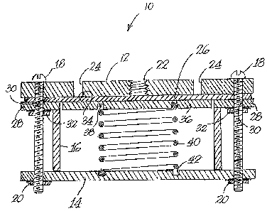
FIGURE 2 is a cross-sectional view of the distribution manifold system of
FI&URE 1.
10 DESCRIPTION OF PREFEI~ED EMBODIMENT
The drawings illustrate a preferred eimbodiment of the fluid distribution
manifold 10 of the present invention. The rnanifold includes a top port plate 12and a bottom end plate 14 which are spaced apart by a cylindrical tubular housing
16. The three components are separably secured together by suitable fasteners,
15 such as the bolts and nuts 18 and 20 shown in the drawings.
The port plate is formed with an a~al fluid inlet 22 and a plurality of
equally angularly spaced fluid outlet openings 24. The fluid inlet is adapted to be
connected to a suitable source of pressurized i~uid in any manner. It is to be
understood that more than one inlet opening may be provided if desired. The
20 fluid outlets are similarly adapted to be connected to components requiring
pressurised fluid.
A flexible gasket or diaphragm 26 engages the underside of the top plate.
The perimeter of the diaphragm is secured to the top plate by a rigid ring 28.
Ring 28 is formed with a plurality of holeis 3û for receiving bolts 18. Nuts 32,2~ threadedly engaged with the bolts, abut the underside of the ring to hold the ring
in position. Ille upper surface 34 of a drcular backing plate 36 engages the
underside of the diaphragm. The undeirside of the backing plate is forrned with
a concentric circular groo~re 38 to receive the one end of a helical compressionspring 40 while the upper surface of end plate 14 is formed with a similar
30 concentric circular groove 42 to receive the lower end of the spring. The spring
serves to urge the diaphragm into engagement with the underside to the port
plate, as shown in FIGURE 2, thereby preventing communication bet~veen the

1 3 1 ~252
- 3 -
inlet and outlet openings. It will be understood that this function can be achieved
in other ways such as, for example, a sealed air chamber (not shown) or a liquidchamber having a d;splaceable chamber (not shown).
The distribution manifold operates as follows. In the absence of a
S minimum or threshold fluid pressure at the inlet, w]hich is determined by the
force applied by the syring, the spring forces the c!iaphragm into engagementwith
the underside of the port plate, thereby sea]ing the inlet and outlet openings and
prevent;ng fluid flow therebetween. When the :fluid pressure at the inlet exceeds
the threshold pressure, the d;aphragm is displaced downwardly toward the end
10 plate which unseats the inlet and outlet openings and forms a chamber betweenthe port plate and the upper surface of the diaphragm. This chamber allows fluidto flow from the inlet opening to each of the outlet openingswhich in turn supply
pressured fluid to the components connected to the outlet openings. When the
pressure is released, the spring urges the diaphragm back into engagement with
15 the port plate which, once again, seals the inlet and outlet openings.
;''~l, j
"

Representative Drawing
A single figure which represents the drawing illustrating the invention.
Administrative Status

2024-08-01:As part of the Next Generation Patents (NGP) transition, the Canadian Patents Database (CPD) now contains a more detailed Event History, which replicates the Event Log of our new back-office solution.

Please note that "Inactive:" events refers to events no longer in use in our new back-office solution.

For a clearer understanding of the status of the application/patent presented on this page, the site Disclaimer , as well as the definitions for Patent , Event History , Maintenance Fee  and Payment History  should be consulted.

Event History

Description Date
Inactive: IPC from MCD 2006-03-11
Time Limit for Reversal Expired 1998-11-17
Letter Sent 1997-11-17
Grant by Issuance 1992-11-17

Abandonment History

There is no abandonment history.

Owners on Record

Note: Records showing the ownership history in alphabetical order.

Current Owners on Record
ROGER GUAY
Past Owners on Record
None
Past Owners that do not appear in the "Owners on Record" listing will appear in other documentation within the application.
Documents

To view selected files, please enter reCAPTCHA code :


To view images, click a link in the Document Description column (Temporarily unavailable). To download the documents, select one or more checkboxes in the first column and then click the "Download Selected in PDF format (Zip Archive)" or the "Download Selected as Single PDF" button.

List of published and non-published patent-specific documents on the CPD .

If you have any difficulty accessing content, you can call the Client Service Centre at 1-866-997-1936 or send them an e-mail at CIPO Client Service Centre.

({010=All Documents, 020=As Filed, 030=As Open to Public Inspection, 040=At Issuance, 050=Examination, 060=Incoming Correspondence, 070=Miscellaneous, 080=Outgoing Correspondence, 090=Payment})


Document
Description 
Date
(yyyy-mm-dd) 
Number of pages   Size of Image (KB) 
Abstract 1993-11-04 1 19
Claims 1993-11-04 2 58
Drawings 1993-11-04 2 51
Descriptions 1993-11-04 3 120
Representative drawing 2001-07-29 1 26
Maintenance Fee Notice 1997-12-14 1 178
Correspondence 1996-12-05 1 13
Correspondence 1996-12-03 2 60
Fees 1994-10-17 1 55
Fees 1995-10-19 1 43
Correspondence 1996-11-25 3 49
Fees 1996-11-13 1 17
Fees 1996-10-22 3 91