Sélection de la langue

Search

Sommaire du brevet 1310252 

Énoncé de désistement de responsabilité concernant l'information provenant de tiers

Une partie des informations de ce site Web a été fournie par des sources externes. Le gouvernement du Canada n'assume aucune responsabilité concernant la précision, l'actualité ou la fiabilité des informations fournies par les sources externes. Les utilisateurs qui désirent employer cette information devraient consulter directement la source des informations. Le contenu fourni par les sources externes n'est pas assujetti aux exigences sur les langues officielles, la protection des renseignements personnels et l'accessibilité.

Disponibilité de l'Abrégé et des Revendications

L'apparition de différences dans le texte et l'image des Revendications et de l'Abrégé dépend du moment auquel le document est publié. Les textes des Revendications et de l'Abrégé sont affichés :

  • lorsque la demande peut être examinée par le public;
  • lorsque le brevet est émis (délivrance).
(12) Brevet: (11) CA 1310252
(21) Numéro de la demande: 1310252
(54) Titre français: TUBULURE DE DISTRIBUTION A SOUPAPES
(54) Titre anglais: DISTRIBUTION VALVED MANIFOLD SYSTEM
Statut: Périmé et au-delà du délai pour l’annulation
Données bibliographiques
Abrégés

Abrégé anglais


ABSTRACT OF THE DISCLOSURE
A fluid distribution manifold comprises a housing having a port plate
having fluid inlet and outlet openings extending therethrough, valve means
disposed in the housing for movement between a closed position whereat the
valve means engages one side of the port plate and sealingly closes each of the
openings and an open position displaced from the port plate whereat the valve
means opens the openings and permits fluid communication therebetween, and
means for urging the movable valve means towards the closed position.

Revendications

Note : Les revendications sont présentées dans la langue officielle dans laquelle elles ont été soumises.


- 4 -
THE EMBODIMENTS OF THE INVENTION IN WHICH AN EXCLUSIVE
PROPERTY OR PRIVILEGE IS CLAIMED ARE DEFINED AS FOLLOWS:
1. A fluid distribution manifold, comprising:
a housing having a port plate having fluid inlet and outlet openings extending
therethrough;
valve means disposed in said housing for movement between a closed position
whereat said valve means engages one side of said port plate and sealingly
closes each said openings and an open position displaced from said port
plate whereat said valve means opens said openings and permits fluid
communication therebetween; and
means for urging said movable valve means towards said closed position.
2. A fluid distribution manifold as defined in claim 1, wherein said valve
means is displaced from said closed position to said open position in response to
a predetermined fluid pressure applied to said inlet opening.
3. A fluid distribution manifold as defined in claim 1 or 2, wherein said means
for urging is a helical compression spring.
4. A fluid distribution manifold, comprising:
a housing having a circular port plate having a central fluid inlet opening
extending axially therethrough, a plurality of equally, angularly spaced fluid
outlet openings extending longitudinally through said port plate, a circular
end plate axially spaced from said port plate and a cylindrical, tubular side
wall extending between and secured to said port plate and said end plate;
a diaphragm disposed in and peripherally sealingly secured to said housing for
movement between a closed position whereat said diaphragm engages one
side of said port plate and sealingly closes each said openings and an open
position displaced from said port plate whereat said diaphragm opens said
openings and forms a fluid chamber which permits fluid communication
openings;

- 5 -
a rigid ring for securing the periphery of said diaphragm to the underside of said
port plate;
a rigid backing plate disposed in said housing for engagement a side of said
diaphragm remote from said port plate; and
a helical compression spring disposed between said backing plate and said end
plate for urging said diaphragm towards said closed position.

Description

Note : Les descriptions sont présentées dans la langue officielle dans laquelle elles ont été soumises.

~ 3 1 0252
The present invention relates to a mani~old systems for distributing fluids
including gases, liquids and flowable solids.
BACKGROIJND OF TElE ~N~ENIION
Fluid distribution mani~old system incorporating one or more check valves
between a fluid inlet and a plurality of fluid outlets are kn~wn ;n the art. Thus,
when a fluid under pressure is applied to the inlet, fluid will flow under uniform
pressure to all components connected to the outlets. When the pressure at the
inlet is released, it is sometimes possible that some fluid will leak from a
non-restricted or partially obstructed outlet. As is well krlown, check valves are
formed with one inlet for receiving fluid, one outlet for delivering Eluid and amovable valve member disposed in a passage connecting the inlet and outlet. The
valve member is arranged to permit fluid flow in one direction only. Conventional
distribution systems, each outlet must be fitted with a check valve to permit topermit fluid flow from the inlet(s) to the outlets. Should an outlet not be fitted
with a check valve, all of the fluid in the system will ultimately escape.
Accordingly, there is a need for a fluid distribution manifold system which
overcomes this problem.
SUMMA~RY OF T~IE INVENTION
The present invention prondes a fluid distribution manifold which
comprises a housing having a port plate having fluid inlet and outlet openings
extending therethrough, valve means disposed in the housing for movement
between a closed position whereat the valve means engages one side of the port
plate and sealingly closes each of the openings and an open position displaced
from the port plate whereat the valve means opens the openings and permits fluidcommunication therebetween, and means for urging the movable valve means
- towards the closed position.
'ir
,...

1 3 1 ~2~2
- 2 -
B~IEF DESCRIPTION OF Tl~E DRA~7VINGS
These anc3 other features of the irlvention will become more apparent from
the following description in which reference is ma~e to the appended drawings
wherein:
S FIGURE 1 is a top plan view of the distribution manifold system according to a preferred embodiment of the present invention; and
FIGURE 2 is a cross-sectional view of the distribution manifold system of
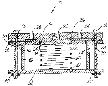
FI&URE 1.
10 DESCRIPTION OF PREFEI~ED EMBODIMENT
The drawings illustrate a preferred eimbodiment of the fluid distribution
manifold 10 of the present invention. The rnanifold includes a top port plate 12and a bottom end plate 14 which are spaced apart by a cylindrical tubular housing
16. The three components are separably secured together by suitable fasteners,
15 such as the bolts and nuts 18 and 20 shown in the drawings.
The port plate is formed with an a~al fluid inlet 22 and a plurality of
equally angularly spaced fluid outlet openings 24. The fluid inlet is adapted to be
connected to a suitable source of pressurized i~uid in any manner. It is to be
understood that more than one inlet opening may be provided if desired. The
20 fluid outlets are similarly adapted to be connected to components requiring
pressurised fluid.
A flexible gasket or diaphragm 26 engages the underside of the top plate.
The perimeter of the diaphragm is secured to the top plate by a rigid ring 28.
Ring 28 is formed with a plurality of holeis 3û for receiving bolts 18. Nuts 32,2~ threadedly engaged with the bolts, abut the underside of the ring to hold the ring
in position. Ille upper surface 34 of a drcular backing plate 36 engages the
underside of the diaphragm. The undeirside of the backing plate is forrned with
a concentric circular groo~re 38 to receive the one end of a helical compressionspring 40 while the upper surface of end plate 14 is formed with a similar
30 concentric circular groove 42 to receive the lower end of the spring. The spring
serves to urge the diaphragm into engagement with the underside to the port
plate, as shown in FIGURE 2, thereby preventing communication bet~veen the

1 3 1 ~252
- 3 -
inlet and outlet openings. It will be understood that this function can be achieved
in other ways such as, for example, a sealed air chamber (not shown) or a liquidchamber having a d;splaceable chamber (not shown).
The distribution manifold operates as follows. In the absence of a
S minimum or threshold fluid pressure at the inlet, w]hich is determined by the
force applied by the syring, the spring forces the c!iaphragm into engagementwith
the underside of the port plate, thereby sea]ing the inlet and outlet openings and
prevent;ng fluid flow therebetween. When the :fluid pressure at the inlet exceeds
the threshold pressure, the d;aphragm is displaced downwardly toward the end
10 plate which unseats the inlet and outlet openings and forms a chamber betweenthe port plate and the upper surface of the diaphragm. This chamber allows fluidto flow from the inlet opening to each of the outlet openingswhich in turn supply
pressured fluid to the components connected to the outlet openings. When the
pressure is released, the spring urges the diaphragm back into engagement with
15 the port plate which, once again, seals the inlet and outlet openings.
;''~l, j
"

Dessin représentatif
Une figure unique qui représente un dessin illustrant l'invention.
États administratifs

2024-08-01 : Dans le cadre de la transition vers les Brevets de nouvelle génération (BNG), la base de données sur les brevets canadiens (BDBC) contient désormais un Historique d'événement plus détaillé, qui reproduit le Journal des événements de notre nouvelle solution interne.

Veuillez noter que les événements débutant par « Inactive : » se réfèrent à des événements qui ne sont plus utilisés dans notre nouvelle solution interne.

Pour une meilleure compréhension de l'état de la demande ou brevet qui figure sur cette page, la rubrique Mise en garde , et les descriptions de Brevet , Historique d'événement , Taxes périodiques et Historique des paiements devraient être consultées.

Historique d'événement

Description Date
Inactive : CIB de MCD 2006-03-11
Le délai pour l'annulation est expiré 1998-11-17
Lettre envoyée 1997-11-17
Accordé par délivrance 1992-11-17

Historique d'abandonnement

Il n'y a pas d'historique d'abandonnement

Titulaires au dossier

Les titulaires actuels et antérieures au dossier sont affichés en ordre alphabétique.

Titulaires actuels au dossier
ROGER GUAY
Titulaires antérieures au dossier
S.O.
Les propriétaires antérieurs qui ne figurent pas dans la liste des « Propriétaires au dossier » apparaîtront dans d'autres documents au dossier.
Documents

Pour visionner les fichiers sélectionnés, entrer le code reCAPTCHA :


Pour visualiser une image, cliquer sur un lien dans la colonne description du document (Temporairement non-disponible). Pour télécharger l'image (les images), cliquer l'une ou plusieurs cases à cocher dans la première colonne et ensuite cliquer sur le bouton "Télécharger sélection en format PDF (archive Zip)" ou le bouton "Télécharger sélection (en un fichier PDF fusionné)".

Liste des documents de brevet publiés et non publiés sur la BDBC .

Si vous avez des difficultés à accéder au contenu, veuillez communiquer avec le Centre de services à la clientèle au 1-866-997-1936, ou envoyer un courriel au Centre de service à la clientèle de l'OPIC.

({010=Tous les documents, 020=Au moment du dépôt, 030=Au moment de la mise à la disponibilité du public, 040=À la délivrance, 050=Examen, 060=Correspondance reçue, 070=Divers, 080=Correspondance envoyée, 090=Paiement})


Description du
Document 
Date
(aaaa-mm-jj) 
Nombre de pages   Taille de l'image (Ko) 
Abrégé 1993-11-04 1 19
Revendications 1993-11-04 2 58
Dessins 1993-11-04 2 51
Description 1993-11-04 3 120
Dessin représentatif 2001-07-29 1 26
Avis concernant la taxe de maintien 1997-12-14 1 178
Correspondance 1996-12-05 1 13
Correspondance 1996-12-03 2 60
Taxes 1994-10-17 1 55
Taxes 1995-10-19 1 43
Correspondance 1996-11-25 3 49
Taxes 1996-11-13 1 17
Taxes 1996-10-22 3 91