Note: Descriptions are shown in the official language in which they were submitted.
1310500
-- 1 --
FABRIC CLEANING
Field of the_Invention
The present invention relates to a cleaning
system, more particularly the present invention
relates to a cleaning system for a fabric such as a
paper machine wire or the like wherein the cleaning
fluid is captured, cleaned and reused. Preferably the
cleaning system directs cleaning fluid through a slot
which extends substantially the full width of the
fabric onto the surface of the fabric as it passes
closely adjacent the mouth of the slot.
Backqround of the Invention
Paper machine wires and the like are
currently cleaned in strips by means of a plurality of
spaced jets that oscillate back and forth transversely
of the wire so that each of the jets cleans a selected
area of the wire. It will be apparent unless there is
perfect synchronization between the wire speed and the
shower oscillations parts o~ the wire may be cleaned
significantly more than other parts in fact it is
quite possible that some parts the wire may never be
cleaned.
The opera-tion of such a jet cleaning davice
requires that the jet strike one side of the wire
driving water and fibres through the wire openings so
- ~ '
1310~0~
- 2 -
that whether or not the opposite side of the wire is
cleaned depends at least in part on fabric design. In
many cases it is very important that both sides of the
wire be properly cleaned, particularly in twin wire
formers where both surfaces of the wire can be equally
contaminated with fibres and fines from the paper
stock.
Obviously when the jet of water and cleaning
fluid hits the wire it is at least partly broken up
into minute drops or mist, this mist floats in the
vicinity of the machine and settles on machine frames,
etc., and forms fibre lumps which can eventually fall
onto the surface of the forming paper web and cause
paper breaks. This mist obviously carries debris into
the atmosphere and increases significantly the
humidity and leads to general discomfort in the
working environment around the machine.
In these conventional nozzle type cleaners
typically about one millimeter in diameter nozzles are
used which requires that the cleaning water be
relatively clean to avoid plugging of the nozzles.
Obviously cleaning of fresh water is expensive and
therefore ignored resulting, in many cases, in the
nozzles frequently becoming plugged.
Furthermore the water used to wash the wire
or fabric is wasted in that it is either lost to
sewer, carried out in the atmosphere around the mill
or contacts and dilutes the white water system
resulting in excess water in the overall system.
Dilution of the white water can be extremely
detrimental particularly in mills where attempts are
being made to close the white water system.
The jets issuing from these nozzles are
relatively high pressure and thus require a high
pressure pump which is not only expensive but is
~3~0~
-- 3 --
troublesome in operation requiring extra maintenance.
High pressure jets abrade the fabric and can in fact
result in fibrillation of the fabric strands.
Another known technique for cleaning a
fabric or wire is by a nip flooding shower wherein the
wire traverses a roll and a shower is directed into
the oncoming nip between the wire and roll. This
system requires a significant amount of water all of
which is either lost to sewer or dilutes the white
water system. The spray is difficult to control and
results in a fibre laden mist that contaminates the
paper machine area and causes sheet breaks. This
system is not particularly effective in cleaning the
surface of the wire that contacts the roll and water
which is retained in the interstices of the wire is
thrown off as the wire travels around rolls
contaminating the surroundings. Plugging of shower
nozzles as occurs with the oscillating high pressure
showers referred to above also poses a problem.
Brief Description of Present Inven_ion
It is an object of the present invention to
provide an improved cleaning system wherein the
cleaning water may be reused and thus need not dilute
the white water system.
It is a further object of the present
invention to provide an improved cleaning system
wherein water sprays may be substantially eliminated
and the cleaning fluid applied through a substantially
continuous slot opening onto and immediately adjacent
the path of the travel of the fabric so that water
leaving the slots immediately passes onto the fabric.
It is still a further object of the present
invention to provide a fabric cleaning station wherein
the water is applied continuously along the slot and
the water is directed through the fabric.
~ 3 1 ~
In accordance with one aspect of the present
invention there i5 provided a fabric cleaning station
through which a fabric to be cleaned travels along a
predetermined path. The station includes a manifold
means on one side of the predetermined path. The
manifold means has a plurality of outlet means through
which cleansing fluid contained by the manifold means
may pass. The station includes fluid communication
means for communicating fluid from the outlet means of
the manifold means to one side of the fabric. The
fluid communication means comprises at least one slot
extending from the outlet means of the manifold means
and extending transverse to the direction of travel of
the fabric through the station. The station includes
wall means spaced from the manifold means defining the
predetermined path along which the fabric travels.
The at least one slot has an opening extending through
the wall means for applying cleansing fluid to the one
side of the fabric. The wall defines a flow
constricting passage extending from the opening of
each the slot and narrowing in the direction of travel
of the fabric for urging the fluid through the
fabric. The station further includes means to collect
the fluid on the other side of the fabric, opposite to
the one side to which the fluid is applied, whereby
fluid issuing from the slot passes through the fabric
and is collected in the means to collect.
Pref~rably the flow constricting passage
tapers from said slot in the direction of travel of
said fabric and is defined between the fabric and a
surface of said wall facing said fabric. The passage
tapering from a maximum depth between the fabric and
the surface adjacent to the slot to a minimum depth at
the end thereof remote from the slot.
In accordance with another aspect of the
~31 ~5~
-- 5 --
present invention there is provided a fabric cleaning
station through which a fabric to be cleaned travels
along a predetermined path. The station includes
manifold means on one side of the predetermined path.
The manifold means has a plurality of outlet means
through which cleansing fluid contained by the
manifold means may pass. The outlet means comprises a
plurality of openings in the manifold. The station
further includes fluid communication means for
communicating fluid from the outlet means of the
manifold means to one side of the fabric. The fluid
communication means comprises at least one slot
extending transverse to the direction of travel of the
fabric through the station. The manifold openings
communicate with the at least one slot. The at least
one slot has a tapered portion for constricting the
flow of cleansing fluid entering the slot from the
manifold openings so as to evenly spread the cleansing
fluid continuously along the slot at the slot opening
adjacent the wall means. The station further includes
wall means spaced from the manifold means defining the
predetermined path along which the fabric travels.
The at least one slot has an opening extending through
the wall means for applying cleansing fluid to the one
side of the fabric. The station also includes means
to collect the fluid on the other side of the fabric,
opposite to the one side to which the fluid is
applied, whereby fluid issuing from the slot passes
through the fabric and is collected in the means to
collect.
In some cases it may be preferred to have a
pair of manifolds one positioned, on each side of the
fabric, to direct the cleaning fluid onto opposite
sides of the fabric in se~uence and to collect the
fluid at opposite sides of the fabric.
i31~500
-- 6 --
Brief Description of the Drawinqs
Further features objects and advantages will
be evident from the following detailed description of
the preferred embodiments of the present invention
taken in conjunction with the accompanying drawings in
which:
Figure 1 is a sectioned view through a
cleaning station diagrammatically illustrating the
cleaning station as well as the recirculation system.
Figure 2 is a view similar to Figure 1
showing a modified station.
Figure 3 is a similar view illustrating yet
another cleaning station.
Figure 4 is a partial perspective view
showing the outlet openings of the manifold and the
manner in which these outlet openings are in fluid
flow communication with the slot passing through the
wall above the fabric.
Figure 5 is an exploded view similar to the
view shown in Figure 4.
Description of Preferred Embodiment
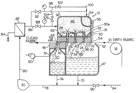
As shown in Figure 1 a dirty fabric 10
enters the cleaning station 12 from the right and
travels to the left in all the Figures. The fabric
passes through the cleaning station 12 under tension
and is directed into close proximity with the surface
of wall 20 via the roll 14 and supports 16 and 18.
The wall 20 is ~ormed in the illustrated arrangement
by a plurality of discrete surface sections 22, 24, 26
and 28 separated by fluid applying slots 30, 32
and 34. Lead in section 22 in the arrangement
illustrated in Figure 1 extends from the beginning of
the surface of wall 20 to the first slot 30 and the
sections 24, 26, and 28 is preceded by slot 30, 32,
and 34 respectively. The slot 30, 32 and 34 each
,
1 310~0~
-- 7
extend transversely to the path of the fabric 10 and
each preferably extends the full width of the
fabric 10. Fresh cleaning fluid is applied to the
fabric from these slots 30, 32 and 34 across the full
width of the fabric.
Referring to Figures 4 and 5 it is seen that
the outlet means of the manifold 46 comprises a linear
series of pipes 30a that extend through a drilled
plate 31. The drilled plate is secured to the top of
10 wall 22, 24, and 26. As a result, the manifold which
houses the cleansing fluid does not have a continuous
slot in its floor. Below each of the series of
pipe 30a, 32a, and 34a of the of the manifold there
extends a the respective slot 30, 32, or 34. From
these Figures it can be seen that each of the
slots 30, 32, and 34 has a tapered portion 35 for
constricting the flow of cleansing fluid entering the
slot from the pipes through openings 37. The purpose
of the tapering portion 35 in the slot 30 is to evenly
spread the fluid received from the manifold 46 along
the entire length of the slot at the opening 39 of the
slot adjacent the wall or walls 22, 24. It should be
understood that this tapering portion should result in
the slot having a narrow part whose area is less than
or equal to the cumulative area of the manifold
openings 37 opening into the slot. Such a limitation
will result in the water spreading along the narrow
portion of the slot.
It will be noted that each of the
sections 24 and 26 define one side and the fabric
defines the opposite side of tapering passage or
gap 38 and 40 respectively, each having its greatest
depth measured perpendicular to the fabric adjacent
the outlet of its respective slot 30 and 32 and its
minimum depth at the end thereof remote from its
~31~0
- 8 -
respective slot 30 and 32. These tapered passages 38
and 40 act as flow constricting passages that tend to
direct or urge the cleaning fluids through the dirty
fabric.
Modified leading surface 28 which leads the
slot 34 in the direction of travel of the fabric 10
defines with the fabric 10 a passage 42 overlying and
extending substantially the full length of the
support 16. Fluid ejected through the slot 34 and
trapped between the fabric 10 and surface 28 passes
over the support 16 through passage 42 with the fabric
and then is directed through the fabric via a
deflecting wall section 44 that blocks off the
passage 42 and approaches very closely adjacent the
upper surface of fabric 10 so that the fluid
travelling through passage 42 is deflected through the
fabric 10 and into the chamber 50 through passage 51
defined between the front of deflection wall 44 and
rear edge of support 16.
Each o~ the slots 30, 32 and 34 communicates
with a manifold or reservoir 46 which provides a
source of cleaning fluid.
Between the supports 16 and the bottom front
wall 47 is a first chamber or container 48 and between
25 the supports 16 and 18 is a second chamber 50. It
will be apparent that the chambers 48 and 50 are
located on the opposite side of the fabric 10 to the
manifold 46 and that the cleaning fluid ejected
through the nozzles or outlet of slots 30, 32 and 34
onto the surface of the fabric 10 passes through the
fabric 10 washing same and is received within the
chambers 48 and 50.
The surface section 28 of the wall 20
terminates before the front edge of the support 18 to
provide a passage or opening 58 to direct air through
131~
g
the fabric 10 and into the chambex 50~ Chamber 50 may
be maintained under negative pressure via suitable
means such as a blower indicated at 60.
A lubricating shower 56 sprays cleaning
fluid down the front wall of the manifold 46 to pass
through the fabric lO and into the chamber 48 through
passage 54 formed between the turned in lip 52 of the
top of wall 47 and the front wall 62 (i.e. the front
end of surface 22).
The nozzle 56 extends substantially the full
width of the fabric lO and showers a fluid down along
the front wall 62 of the manifold 46 to keep that
front wall clean. The cleaning fluid used in the
shower 56 may be of a different composition to that
15 used in the various slots 30, 32 and 34 and thus a
separate chamber or manifold 64 is used to supply
fluid into the nozzle of shower 56.
This shower 56 is not absolutely essential
and may, if desired, be eliminated completely.
The cleaning fluid which normally will be
water is recirculated via a pump 70 that draws the
cleaning fluid from the chambers 48 and 50 via
lines 72 and 74 into the main line 78 leading to the
pump 70. Cleaning fluid from the pump 70 passes via
line 80 to a filter system 82 with the rejects from
the system 82 being either sewered or sent back to the
white water system as indicated by the arrow 84. The
cleaning fluid from the filter passes via line 86
directly into the manifold 46. Flow is controlled by
a suitable valve 88. If a lubricating shower
equivalent to the shower 56 is used and if a separate
supply of fluid is provided for example by the use of
the manifold 64 fluid is returned to the manifold 64
via line 90 with flow therethrough being controlled
via valve 92.
~31~0~
-- 10 --
Fresh water enters the system via line 94
under the control of the valve 96.
In some cases it will be desired to add
chemicals either to fluid issuing from nozzle 56 or
supplied to the manifold 46 or both. In such cases
cleaning chemical is maybe provided via line 98 and
supplied to the reservoir or manifold 64 via line 100
under control of the valve 102 and/or maybe directed
to the manifold 46 via line 104 under the control o~
valve 106.
The arrangement shown in Figure 1 operates
as follows:-
Fresh cleaning fluid in the manifold 46passes through the pipes 30a, 32a, and 34a and into
the slots 30, 32 and 34 and is directed against one
surface (the top surface) of the dirty fabric 10. It
should be understood that the pipes extend above the
floor of the manifold 46 so that any debris in the
manifold settles to the floor and is not transferred
to the fabric. The tapering portion 35 in the
slots 30, 32, and 34 acts to spread the fluid evenly
along the slots adjacent the fabric. The fluid
issuing from the nozzles or slots 30 and 32 is forced
through the fabric 10 via the wedge shaped outlet
passages 38 and 40 formed in the surfaces 24 and 26 is
collected in chamber 48. Some of the aleaning fluid
ejected through the nozzle 34 passes directly through
the fabric 10 into c~ee~e~ in the chamber 48.
~J~
Cleaning fluid from nozzle 34 remaining in or above
the fabric passes via the passage 42 over the
support 16 and is directed by the deflecting
section 44 of surface 28 through passage 51 into the
chamber 50. Preferably the chamber 50 will be
maintained under a negative pressure via the blower 60
so that air will be drawn in through the passage 58 to
~ 131~00
drive further water from the fabric and dry the
fabric lO. Fluid from the chambers 48 and 50
discharges via lines 72 and 74 into the main line 78
and is moved via the pump 70 through line 80 to the
filter 82. Debris separated in the filter system 82
is carried in line 84 either to sewer or returned to
the white water system (not shown) and the cleaned
fluid then passes via line 86 into the manifold 46 to
be reused and passed through the slots 30, 32 and 34
onto a following portion of the fabric lO and line 90
to manifold 64.
When the fluid to be applied via the
shower 56 is different from the fluid applied via the
slots 30, 32 and 34 suitable amounts of cleaning
chemical may be added to the flow into the manifold 64
via the line 100.
~s above described if desired suitable
cleaning chemicals may also be added into the washing
fluid in the manifold 46 via line 104.
When the lubricating shower 56 is operating
fluid from the shower passes down the front wall 62 of
the manifold 46 onto the top surface of the fabric lO
and passes through the fabric lO to the reservoir 48
through the gap 54 between the lip 52 and the front
wall 62 and surface 22.
The arrangement permits recirculation of the
cleaning fluid and thus eliminates any problem of
contamination or dilution of the white water by
washing fluid. The passage of air through the
fabric lO and into the chamber 50 tends to dry the
fabric and thereby improve its condition when it is
returned to contact the paper stock.
The arrangement shown in Figure 2 is quite
similar to that shown in Figure l however in this case
with the system illustrated no separate lubricating
- 131~0
-- 12 --
chemical is being used in the lubricating shower 56
thus the cleaning fluid that is used in the
slots 30, 32 and 34 is used in the shower 56. In the
arrangement illustrated in Figure 2 only 2 slots i.e.
those equivalent to 30 and 32 have heen provided each
of which will have its leading surfaces 24 and 26 with
the wedge shaped passages 38 and 40 respectively
provided therein. Basically the difference between
the Figure 2 embodiment and that in Figure 1 is that
only two slots 30 and 32 have been provided and
passage 42 has been eliminated.
An opening 108 is provided between the rear
wall 63 of the manifold 46 i.e. the rear end of
surface 26 and the adjacent edge of the support 16 so
that air may pass through the fabric 10 into the
chamber 48. Air is drawn through opening 108 and
chamber 48 is maintained at below atmospheric pressure
by blower 60. The remainder of the system is
essentially the same as Figure 1~ If desired instead
of air being simply drawn through the fabric 10 into
the chamber 50 via a negative pressure produced by the
pump 60 the air under pressure for example from the
pump 60 may be directed to a chamber 110 as shown in
dotted lines to indicate its optionallity and blown
positively through the fabric 10 and into the
chamber 50. Air may be similarly blown into '!
chamber 48 through opening 108.
If desired the added fresh water in line 94
may contain some cleaning chemical.
The arrangement shown in Figure 3 is similar
to that shown in the other Figures however in this
arrangement only a single slot 30 is provided above
the wire. The fabric 10 is deflected via the leading
surface 22' and passes along the surface 24' which
maybe provided with the same wedge shaped passage 40
13105~0
- 13 -
leading from the slot 30. The surfaces 22 and 24
combine to form a convex curved surface of wall 20
around which the fabric 10 passes.
In the arrangement of Figure 3 a bottom
manifold or reservoir 112 is provided for supplying
fluid to a nozzle or slot 116 formed in a support
surface 114. The surface 114 may be flat or convexly
curved and the slot 116 may be similar to the nozzle
or slot 30. Fluid issuing from the nozzle or slot 116
from manifold 112 passes through the fabric 10 and is
directed by auto slice 118 into a receiving
chamber 102. Fluid from chamber 120 passes via
line 122 to the main return line 78 to the pump 70.
A suitable gap 54' is provided between the
support 114 and the surface 22' so that some of the
cleaning fluid passing from slot 116 into the
fabric 10 may pass through the slot 54 into the
chamber 48. In this arrangement fluid from
chamber 120 passes via line 12 to return line 78 for
pump 70 and fresh cleaning fluid from the filter
system 82 is carried by line 124 under control of
valve 126 into the reservoir or manifold 112. The
support surface 114 and nozzle or slot 116 etc, may be
us~d in the Figure 1 or 2 embodiments.
Embodiments in Figures 2 and 3 operate in
the same manner as described above with respect to the
embodiment of Figure 1 however in the Figure 2
embodiment only a pair of slots 30 and 32 have been
provided and air may optionally be blown into the
chamber 118 and/or 50 (as could have been done with
the Figure 1 embodiment). In Figure 3 liquid is
directed to opposite sides of the fabric via the
slots 116 and 30 respectively so that cleaning fluid
passes first to one direction through the ~abric and
then in another direction through the ~abric.
l~o~oa
- 14 -
Throughout the disclosure term fabric has
been used which is intended to include forming wires
as used in fourdrinier machines, twin wire formers or
any other type of machines for manufacture of paper or
pulp sheet. The term is also intended to include
felts such as the press or drier felts used in
manufacture of paper.
Modifications will bs evident to those
skilled in the art without departing from the spirit
of the invention as defined in the appended claims.
!
~ .
.